Ed Nisley's Blog: Shop notes, electronics, firmware, machinery, 3D printing, laser cuttery, and curiosities. Contents: 100% human thinking, 0% AI slop.
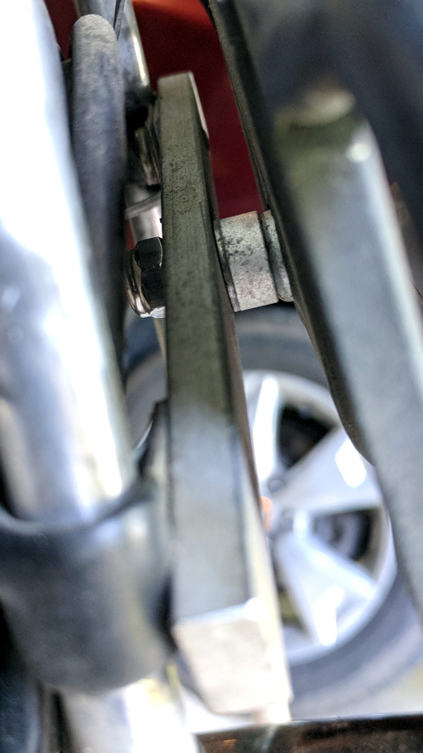
Long ago, I conjured a front rack mount from an aluminum bar across the seat struts on our Tour Easy recumbents, with a spherical washer soaking up the angular misalignment. The rack on Mary’s bike developed a serious wobble due to a missing screw, which was easy enough to replace:
Rack mount screw – rear
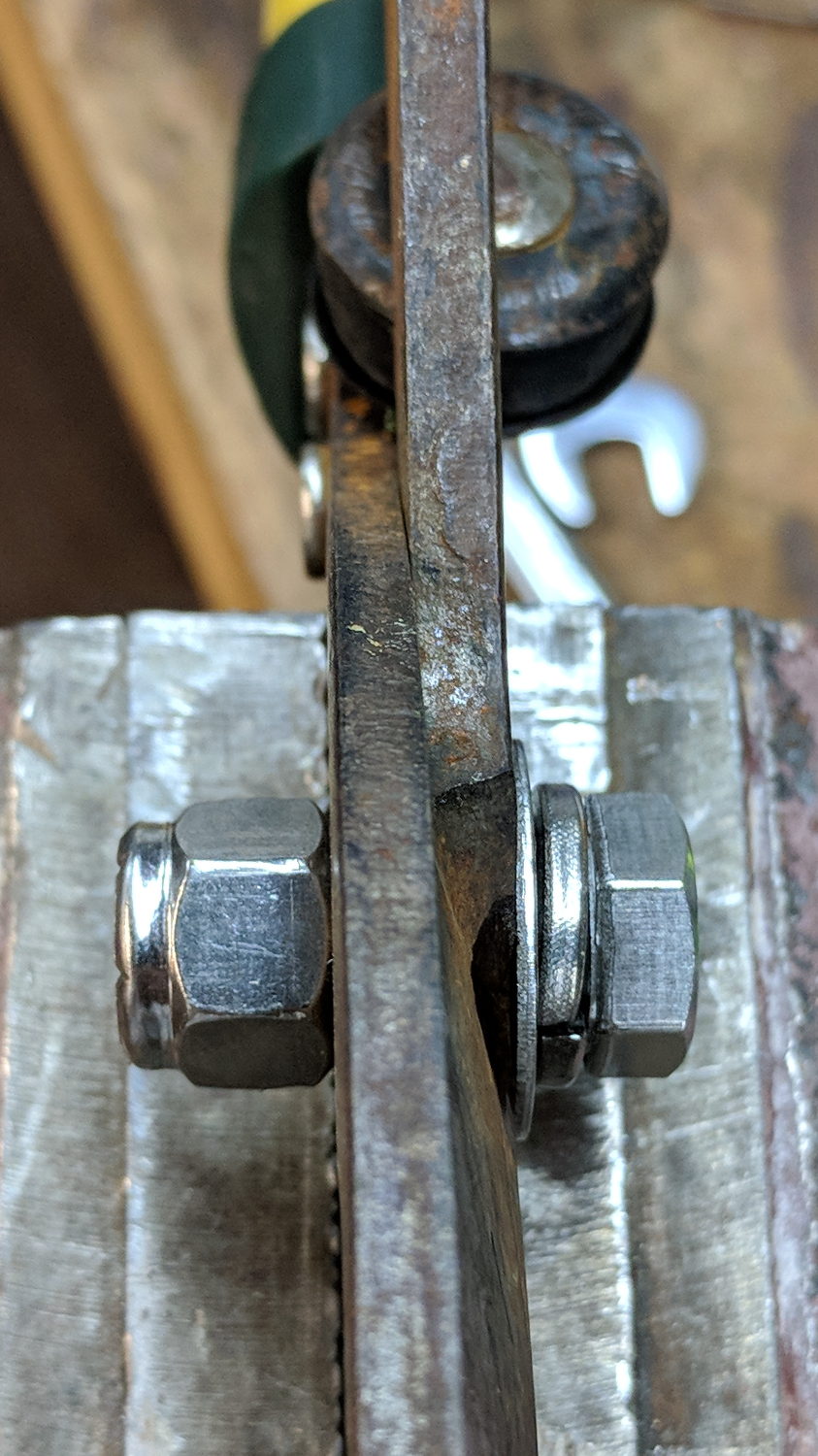
From the side:
Rack mount screw – side
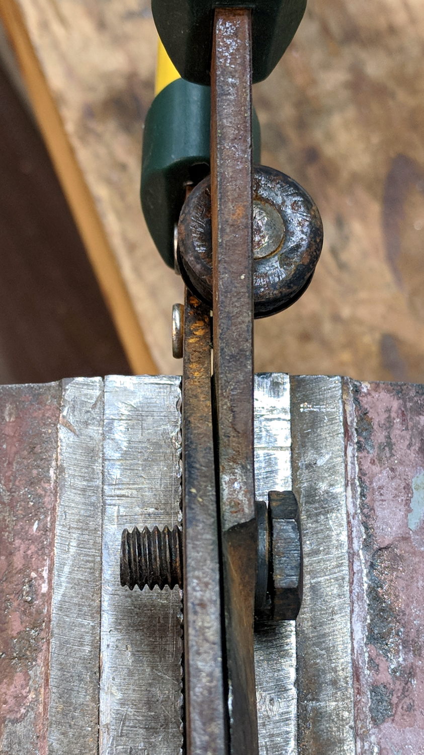
It’s a 2 inch screw sawed down to 1.5 inch, ground to shape, then run through a die to clean up the threads.
The nylon lock nut over on the left should keep the screw from working its way out of the tapped aluminum bar. On the other paw, a dab of Loctite survived nearly a decade of heavy loads and vibration.
Some surreptitious brush clearing called for a tool larger than our wonderful Fiskars PowerGear pruner, so I unearthed a long-disused bypass lopper in the garage (it may have Come With The House). Alas, the pivot bolt lost its jam nut long ago:
Bypass loppers – OEM 10 mm bolt
That’s an M10x1.5 bolt, for which I lack a corresponding nut.
But 3/8-16 is approximately M10x1.5, for small values of thread engagement, and I do have an assortment of inch-sized stainless steel fasteners:
Bypass loppers – 0.375 inch bolt
The nylon lock nut jams the bolt against the left blade, with the split washer applying pressure to the tapered blade. Slobbering oil in the sliding joints restored it to perfect working order.
The weird round dingus on the far side of the pivot, up against the handles, is a bumper cushioning the fully closed position. It’s a nice touch and might work better if its rubber pad hadn’t aged out over the decades spent in the garage waiting for this very day.
It’s my kind of yard work: “What do you need killed next?”
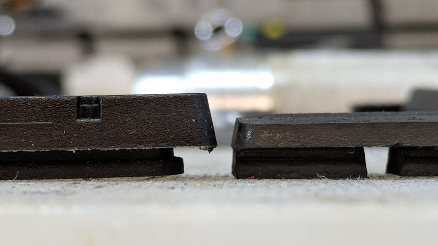
The rear brake on my bike wasn’t stopping nearly as well as it should, even after cleaning the rim and pads with brake cleaner, so I pulled the shoes and replaced the pads:
Bike brake pad wear
It’s down a bit beyond the --WEAR--LINE-- indicator, of course.
New brake shoes on clean rims work exactly like they should!
That’s with the card jammed into an Anker USB 3.0 adapter and both devices plugged into the two USB 3.0 “Super Speed” ports in the front of my desktop box. Plugging them both into the adjacent USB 2.0 ports drops the data rate to 18 MB/s.
The Sandisk card claims read-write speeds of “up to” 20 MB/s, so it’s the limiting factor.
Getting reliable performance numbers is surprisingly difficult:
dd bs=4M count=1000 status=progress if=/dev/urandom of=/mnt/part/random.bin
4177526784 bytes (4.2 GB, 3.9 GiB) copied, 214.064 s, 19.5 MB/s
1000+0 records in
1000+0 records out
4194304000 bytes (4.2 GB, 3.9 GiB) copied, 214.922 s, 19.5 MB/s

dd bs=4M count=1000 status=progress if=/dev/urandom of=/mnt/part/random2.bin
4194304000 bytes (4.2 GB, 3.9 GiB) copied, 217.08 s, 19.3 MB/s
1000+0 records in
1000+0 records out
4194304000 bytes (4.2 GB, 3.9 GiB) copied, 217.08 s, 19.3 MB/s
Obviously, prying bits out of the random number generator limits the overall write speed.
Zeros, however, are cheap and readily available:
dd bs=4M count=1000 status=progress if=/dev/zero of=/mnt/part/null.bin
4169138176 bytes (4.2 GB, 3.9 GiB) copied, 23.0091 s, 181 MB/s
1000+0 records in
1000+0 records out
4194304000 bytes (4.2 GB, 3.9 GiB) copied, 23.1775 s, 181 MB/s

dd bs=4M count=1000 status=progress if=/dev/zero of=/mnt/part/null2.bin
4093640704 bytes (4.1 GB, 3.8 GiB) copied, 25.031 s, 164 MB/s
1000+0 records in
1000+0 records out
4194304000 bytes (4.2 GB, 3.9 GiB) copied, 25.7781 s, 163 MB/s
But the caches take a while to drain, even after the command returns:
time ( dd bs=4M count=1000 status=progress if=/dev/zero of=/mnt/part/null3.bin ; sync )
4118806528 bytes (4.1 GB, 3.8 GiB) copied, 23.0004 s, 179 MB/s
1000+0 records in
1000+0 records out
4194304000 bytes (4.2 GB, 3.9 GiB) copied, 23.5305 s, 178 MB/s

real	0m35.887s
user	0m0.008s
sys	0m4.824s
Dividing 4 GB / 35.9 s says the mechanical write speed is close to 110 MB/s.
Reading proceeds a bit faster, while also running up against the effect of the many caches between the spinning platter and the screen:
time ( cp /mnt/part/random.bin /dev/null )
real	0m36.565s
user	0m0.048s
sys	0m1.712s

time ( cp /mnt/part/random.bin /dev/null )
real	0m29.157s
user	0m0.036s
sys	0m1.800s

time ( cp /mnt/part/random.bin /dev/null )
real	0m10.265s
user	0m0.028s
sys	0m1.040s

time ( cp /mnt/part/random.bin /dev/null )
real	0m0.608s
user	0m0.004s
sys	0m0.600s

time ( cp /mnt/part/random.bin /dev/null )
real	0m0.590s
user	0m0.008s
sys	0m0.580s

time ( cp /mnt/part/random2.bin /dev/null )
real	0m31.035s
user	0m0.056s
sys	0m1.816s

time ( cp /mnt/part/random2.bin /dev/null )
real	0m31.024s
user	0m0.052s
sys	0m1.860s
Unsurprisingly, copying a brace of 4 GB files in parallel takes twice as long as each cold-buffer read, so disk’s raw read speed seems to be around 130 MB/s.
The drive’s write speed won’t be the limiting factor while saving camera video data!
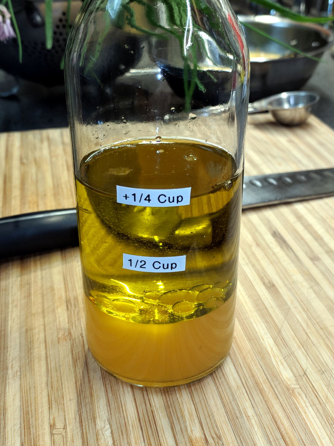
Mary used to mix up her oil-and-vinegar dressing using a measuring cup, then she drew markings on the bottle, then I added tidy labels:
Calibrated Oil-and-Vinegar bottle
The labels align with her process: she adds ½ C oil first, then ¼ C vinegar, then various other ingredients. The liquids swirl around, sort themselves out, and it’s all good.
Surprisingly, the labels survived uncounted dishwasher adventures.
Apparently folks have been going around the curve in front of the Dutchess County BOCES site at a pretty good clip. I didn’t spot any scars in the grass off the high side, but ya never know.
We’re at the top of an uphill section and, riding together, we’re not sprinting for town line signs.
The ESP8266 controller in Sophi’s blimp project suffered from random resets, which I was absolutely certain happened when the current for the three DC prop motors glitched the battery supply. So I hauled the Tek current probes + amps + scope to a Squidwrench meeting and, after considerable fiddling, we found a smoking … trace:
Regulator dropout
The purple trace shows the Li-Ion battery voltage at an inactive motor driver located on the far end of a known-to-be-too-small trace. In principle, there’s little-to-no current drawn through that trace, so it should represent the voltage at the regulator input.
The green trace shows the 3.3 V regulator output at its bulk storage cap.
The ground reference is at the PCB’s battery negative connection pad.
The bold dotted green cursor shows the regulator output hitting 2.57 V, entirely low enough to glitch the ESP. The scope triggers on negative-going edges below 2.6 V and this was the first trigger after starting and running the motors for a few seconds.
Conspicuous by its absence: any hint of a current glitch in the yellow trace from a Tek A6302 probe clamped around the battery positive wire. The current remains constant at the 400 mA (100 mA/div) level drawn by two DC motors, with no sign of any glitches whatsoever; she’s not using PWM speed control. The whole board draws about 80 mA DC and the ESP’s WiFi radio pulls 200 mA pulses, so all’s quiet on those fronts.
Which is why I like to measure actual circuit operation: I vastly prefer to solve actual problems, knowing what does (or doesn’t!) cause them helps, and I’m not at all bothered by being wrong.
The regulator output doesn’t go much above 3.3 V, which is comforting.
However, when the regulator’s input voltage falls below 3.3-ish V, its output voltage tracks right along down with it. Input variations above 3.3-ish V don’t make much difference in the output.
Although it’s a buck-boost converter, its response time isn’t fast enough to cope with something else on the PCB pulling enough current to spike its input voltage (shared with the motor driver) below 3.3 V. The dropout is barely 4 ns long, far shorter than the regulator’s switching period.
I have my doubts as to the accuracy of those voltage waveforms and, in particular, their pulse widths. IIRC, the scope can trigger on a pulse exceeding a specific width, but I’d devote more time arranging the test points and getting RF-quality connections / grounding before going further out on a numeric limb.
This single trigger event may not be the glitch causing the reset. What it does show is the regulator output dropping below the ESP’s absolute-minimum input voltage spec, at least briefly, which is cause for concern.