Ed Nisley's Blog: Shop notes, electronics, firmware, machinery, 3D printing, laser cuttery, and curiosities. Contents: 100% human thinking, 0% AI slop.
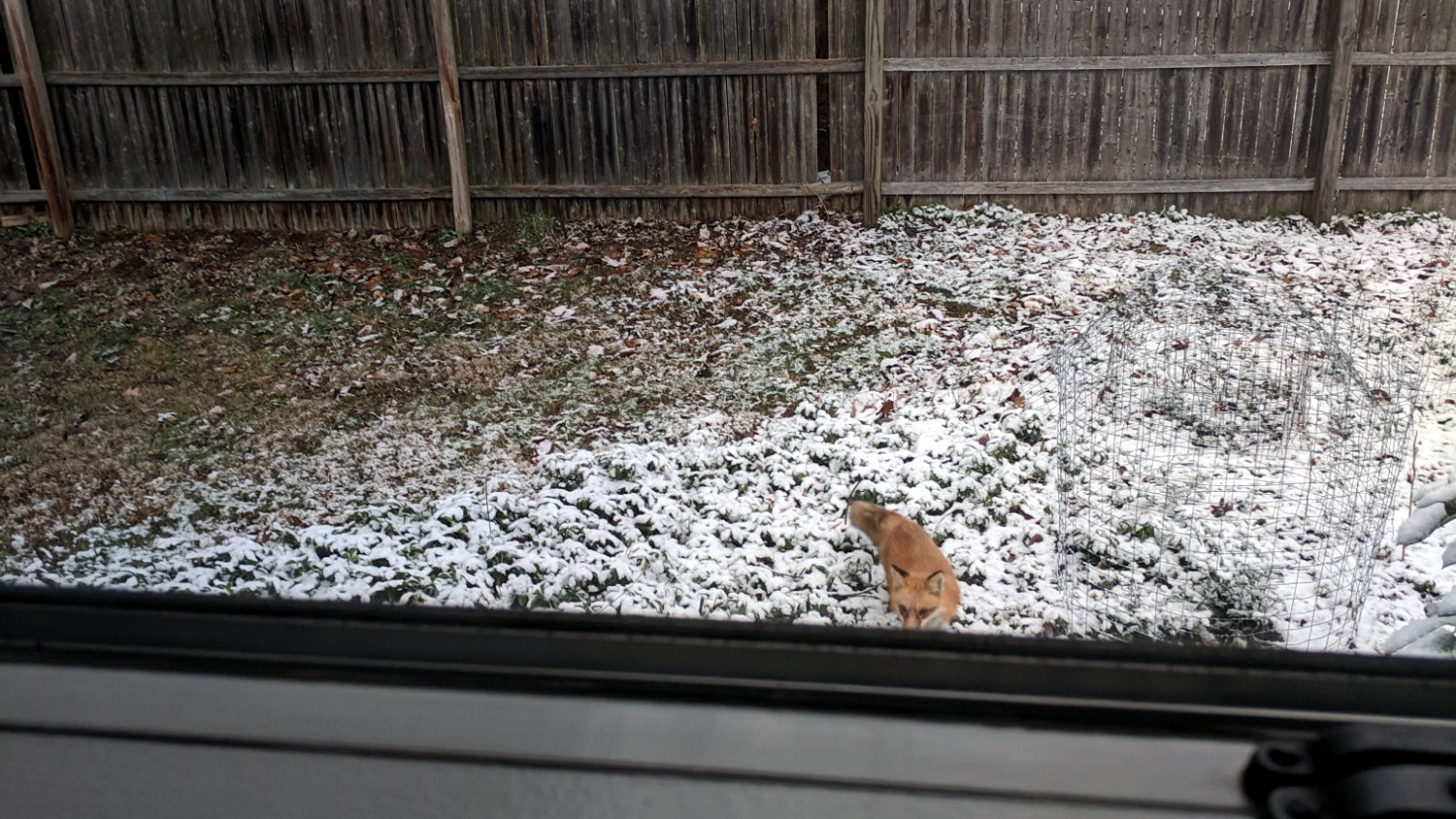
A Red Fox came trotting around the garden on the day before Christmas, then nosed up to the back of the house:
Red Fox visitation – 2018-12-24
Presumably, it was in search of a snack. We wish it good hunting.
A few hours later, the fox walked quickly across the back yard with half a dozen turkey toms close behind, perhaps urging it away from their hens. Everybody remained calm and collected, knowing their roles in this particular play.
FWIW, Marist College fields Red Foxes athletic teams. The women’s teams are Lady Red Foxes, as “vixen” carries entirely inappropriate connotations.
A bag of 100 nF ceramic caps arrived from across the continent (“US Stock”) and failed incoming inspection:
Mislabeled 100 nF ceramic capacitor – actual 50 nF
The capacitor mark says 104, which is what you’d expect on a 100 nF cap, but the first half-dozen out of the bag measured around 55 nF, far outside even the loosest -20%/+50% tolerance.
Stipulated: the factory can ship every capacitor it makes with a proper mark.
Given their (lack of) provenance, they could be mis-marked 47 nF caps.
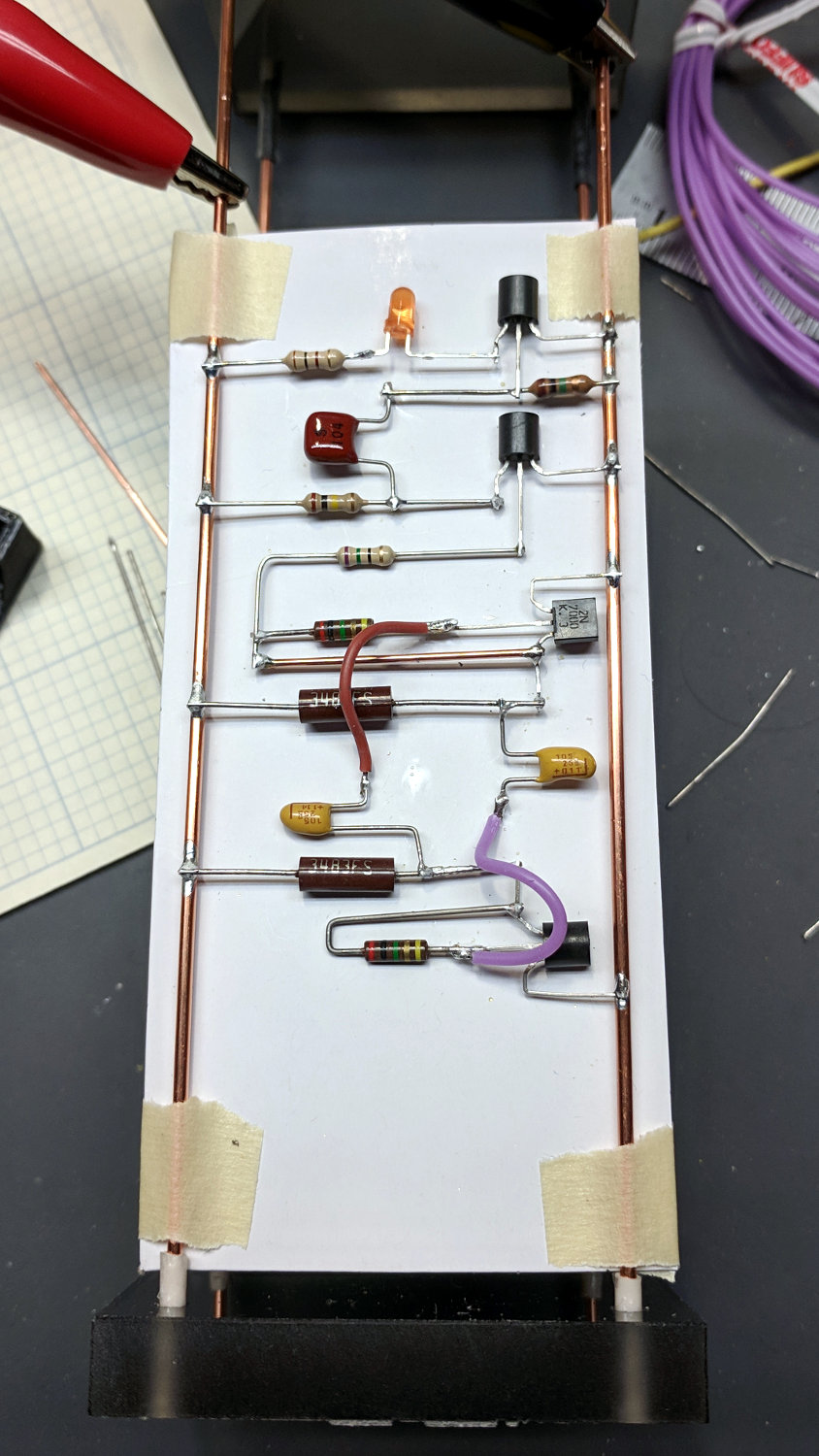
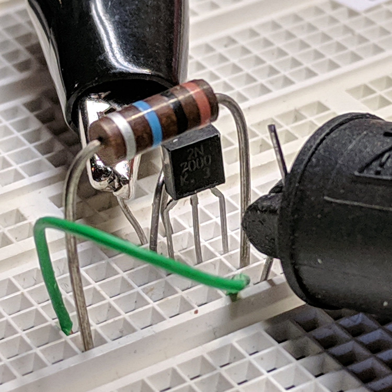
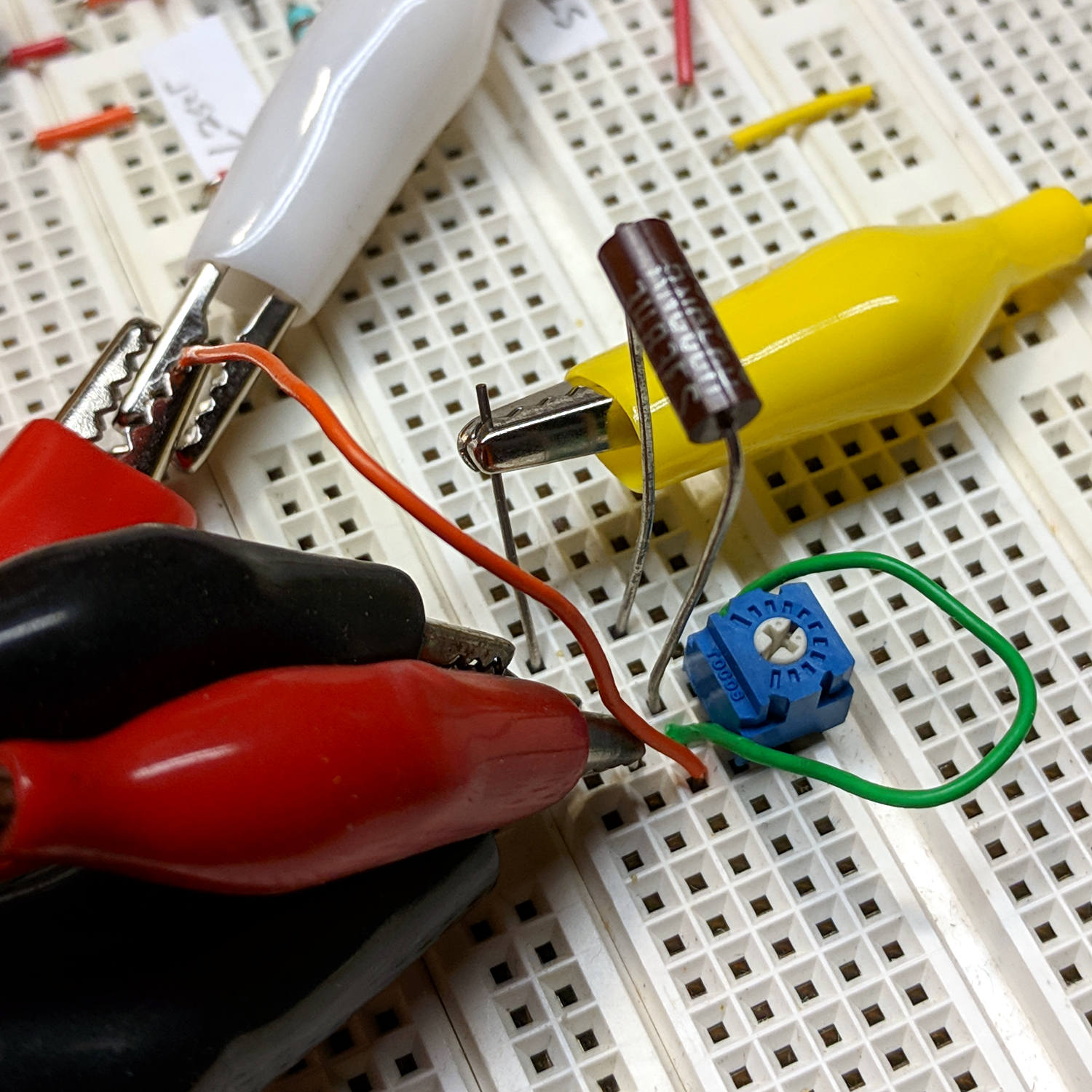
Taping a cardboard support under the soldering fixture helped hold all the parts in place:
Astable – 2N7000 soldering
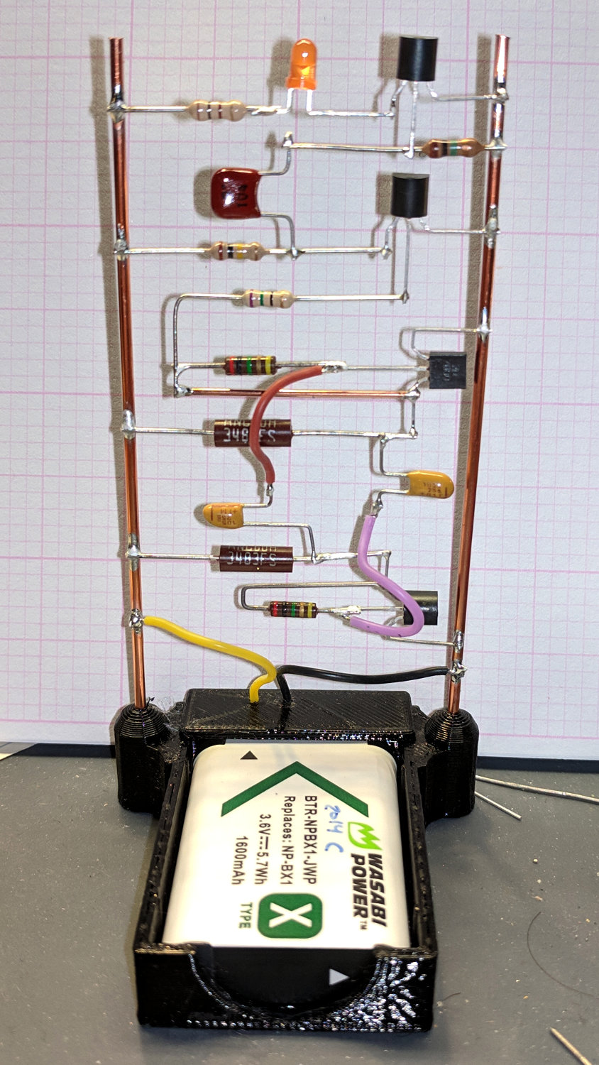
The struts fit neatly into an NP-BX1 battery holder and the circuit began blinking merrily:
Astable – 2N7000 assembled
My photography hand is weak …
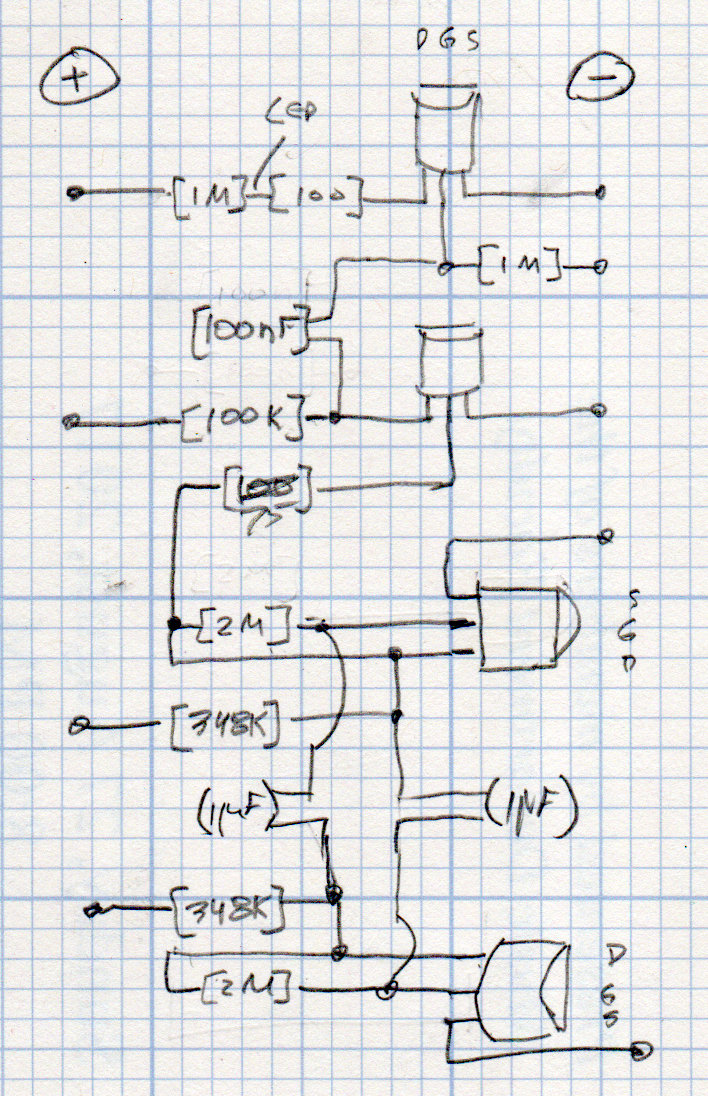
The circuit schematic / layout resembles this:
LED Schematic – MOSFET transistors
The missing 1 MΩ resistor at the LED would serve as a physical support to tether the loose end of the 100 (-ish) Ω resistor, which desperately needed some stabilization under the LED spider.
The simulation says it should blink about every 4s:
Astable – 2N7000 buffered – true model
The 2N7000 MOSFETs use a SPICE model from the Motorola ON Semi downloads, although they behaved about the same way using the LTSpice 2N7002 model.
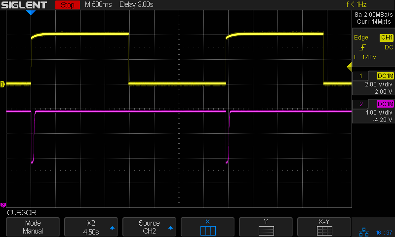
It really does blink every 4s:
Astable – 2N7000 overview
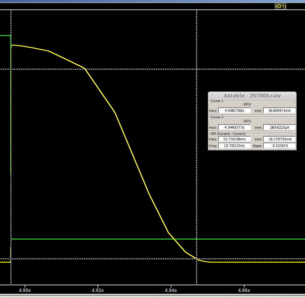
The LED pulse width should be about 50 ms:
Astable – 2N7000 buffered – LED current – true model
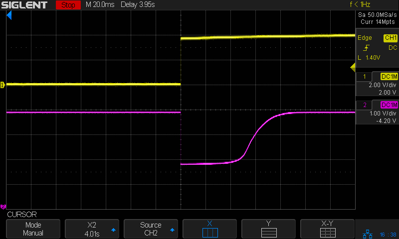
The voltage at the bottom of the ballast resistor is directly proportional to the LED current:
Astable – 2N7000 pulse detail
So the pulse is actually 80-ish ms, which is Close Enough™ for my purposes.
The key advantage here is making both the astable’s period and the blink’s duration (roughly) proportional to the component values, so I can tweak them with some confidence the results will come out more-or-less right.
[ed@shiitake tmp]$ lxi screenshot -a 192.168.1.41 -p siglent-sdm3000 test.bmp
Saved screenshot image to test.bmp
[ed@shiitake tmp]$ convert test.bmp test.png
convert-im6.q16: length and filesize do not match `test.bmp' @ warning/bmp.c/ReadBMPImage/831.
Files stored on a USB stick jammed into the meter’s front panel have the correct size, so it’s not clear where the fault lies.
Because the files contain extra data following the (intact) image, it will display correctly:
Astable – 2N7000 – IDSS cal
The BMP header contains the correct size at offset +0x02:
The horizontal image size at +0x12 and vertical size at +0x6 are correct: the screen is 480×272 pixels. Each pixel has three bytes = 24 bits, as specified at +0x1C.
So the file should contain 0x0005fa36 = 391734 bytes, but, as delivered, it’s much, much larger:
ll --block-size=1 test.bmp
-rw-rw-r-- 1 ed ed 1152054 Dec 26 08:45 test.bmp
Oddly, 1552054 bytes is exactly the size the oscilloscope files should be. I have no explanation, although it looks like a copypasta error.
As before, the simplest solution is to truncate the file and be done with it:
Some poking around revealed an astable multivibrator using now-obsolescent ZVNL110A MOSFET transistors. The key idea seems to be large gate resistors putting the DC operating point exactly at the voltage required to hold each transistor in the linear region, pretty much guaranteeing the astable will eventually start up.
A bit of simulation suggests this variation ought to work:
Astable – 2N7000 buffered
Well, after the kickstarter in the lower left shorts the transistor for millisecond to enforce some asymmetry, whereoupon the simulation ticks along just fine.
The yellow trace shows the voltage across C2 ramping back and forth between ±1.3 V, with a period just over 4 s and almost exactly a 50% duty cycle: much better than the bipolar version, with sensible component values. As before, the cap sees both polarities, so an electrolytic cap isn’t appropriate.
The red trace is the drain voltage at M2 (presumably, “M for MOSFET”, rather than a plebeian “Q” or “T”), which is firmly at 0 V when it’s ON and ramps upward as R4 pulls C1 higher to turn it even more firmly OFF.
The green trace shows the LED current pulse when M2 turns ON at the end of each cycle. Rather than contort the astable into a very low duty cycle, I generate the pulse by dumping current through a smallish cap into the gate of M4. A few tens of milliseconds makes a perfectly serviceable blink and keeps the average current drain down around a milliamp or so.
In between, M3 buffers the astable’s output to deliver enough current to C4. Without the buffer, the cap draws enough current to mess with the oscillations; that’s how I got backed into this corner.
Figuring the LED at 20 mA for 50 ms, the astable at 10 µA, and the buffer at half of 40 µA, the average current of 1 mA comes entirely from the LED, so even a weak lithium camera battery should last a good long while.
If the low average drain ekes 1000 mA·h from the battery, the LED should blink for a month or two before the battery shuts down.
Building an astable multivibrator from MOSFETs for longer time constants and more reliable operation suggests I should know a bit more about their operation with minuscule currents and low voltages. I have a small stock of low-threshold ZVNL110A MOSFETs, but using something less obsolete seems in order.
Dirt-cheap 2N7000 MOSFETs have a maximum IDSS around 1 µA at room temperature, which would be way too high in this situation; there wouldn’t be much difference between their ON and OFF states.
The test setup is simplicity itself:
2N7000 IDSS – calibration
The initial reading from a 4 V bench supply was 0.00 µA on the Siglent SDM3045, my best low-current meter, so I put a 10 MΩ resistor across the drain and source terminals:
Astable – 2N7000 – IDSS cal
Close enough, particularly given the silver fourth band on that old carbon composition resistor and its no-doubt unclean surface.
The rest of the 2N7000 MOSFETs have IDSS ≤ 10 nA, which you can’t distinguish from zero on that scale.
The 2N7000 datasheet specs give a threshold voltage from 0.8 to 2.5 V for 1 mA drain current, bracketing a 2.1 V typical value, which would be too high for a nearly dead lithium cell.
I calibrated the VGS(thr) current at 11 µA with a 348 kΩ resistor:
2N7000 MOSFET Id cal
Which produced 11.49 µA at 4 V, just as it should, so I plugged in a MOSFET and twiddled the trimpot for a nice round 10 µA:
2N7000 MOSFET Vthr test
Most transistors conducted 10 µA with the gate at 1.42 V, with a few outliers spanning 50 mV on either side. Close enough and low enough!.
We hung a pine-cone wreath beside the back door (a.k.a. the only door we use), replacing a Welcome sign painted on a slate tile. Of course, the tile had long provided a sheltered spot against the house siding: