The Branson 200 ultrasonic cleaner in the bathroom has been with me for a long time. If I’m reading the IC date codes correctly, it’s one of the first things I bought after real paychecks began arriving back in 1974:
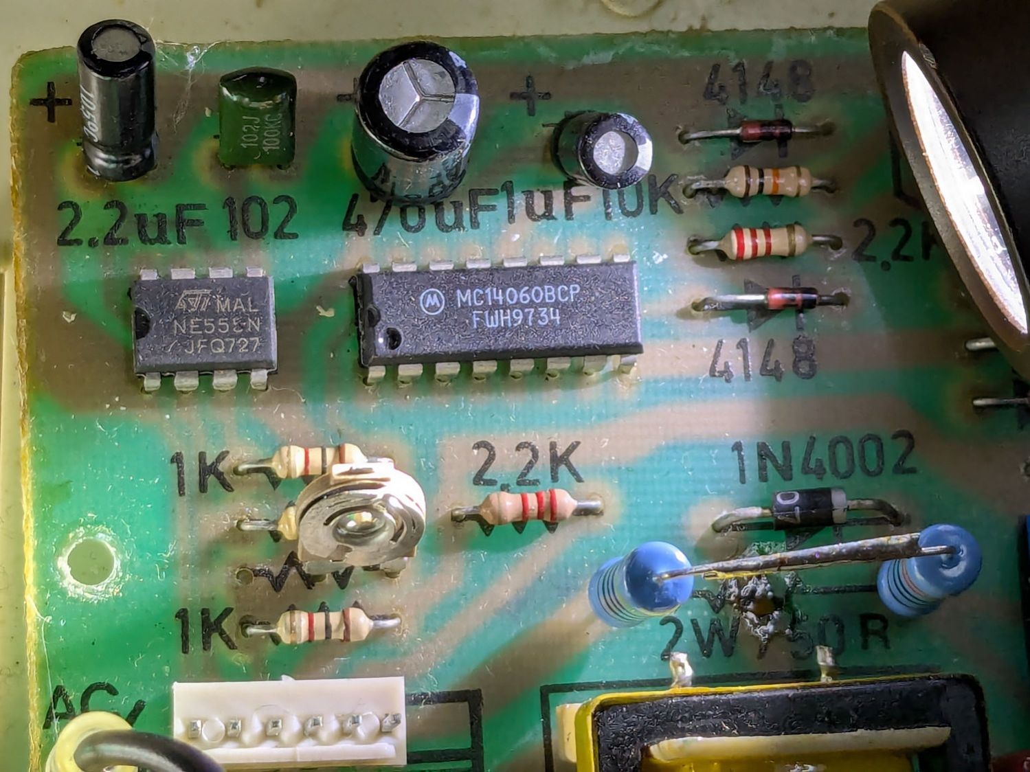
The circuit board has that spacious old-time layout:

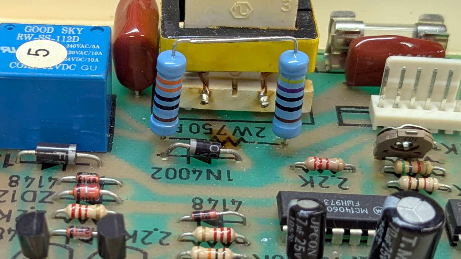
Believe it or not, this isn’t why I took the thing apart:

I’ve never seen a PCB with the component values printed on it, but they definitely came in handy!
That resistor measured 743 Ω: still good, even with an extra-crispy coating.
Assuming it was dissipating a bit more than its 2 W rating could handle, I replaced it with a 470 Ω + 330 Ω series combination of 2 W 1% metal film resistors:
In parallel with a 15 kΩ resistor on the back of the PCB to bring them down to 759 Ω:
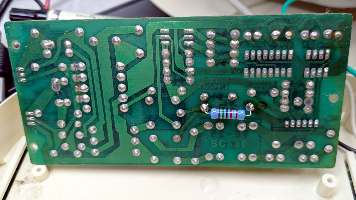
Which seems Close Enough™.
The 470 Ω resistor will dissipate 60% of whatever toasted the original resistor, so it should survive for Long Enough™.
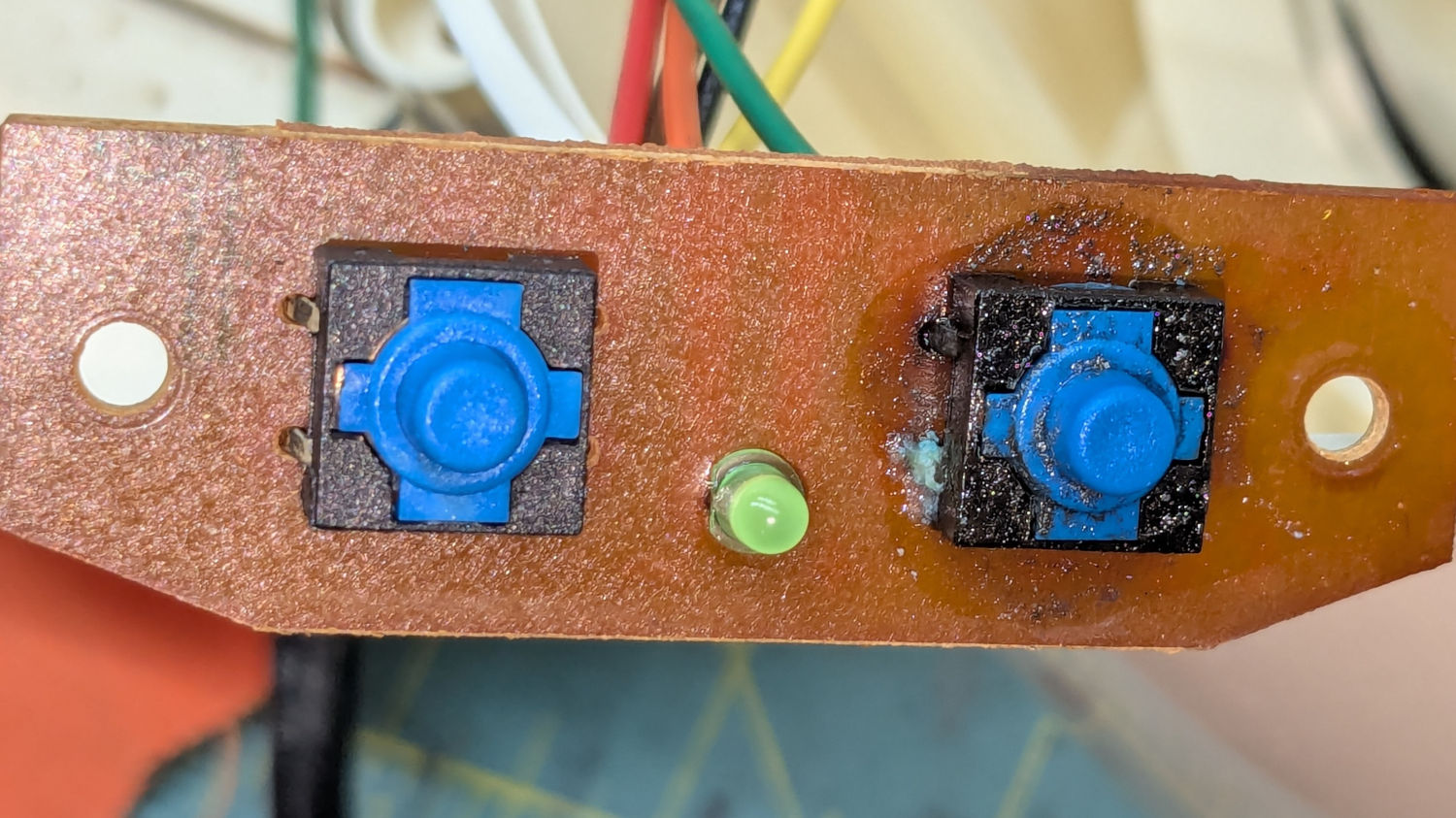
With that settled, the real reason I took the thing apart was the power switch had finally failed:
Because the Kapton tape I’d used most recently to cover the disintegrating original switch cover had begun leaking:
There should be a black disk inside the hole for the 1 switch, but it had long ago broken free and was held in place only by the failed Kapton tape.
A pair of switches from the Warehouse Wing fit perfectly into the holes of the PCB:
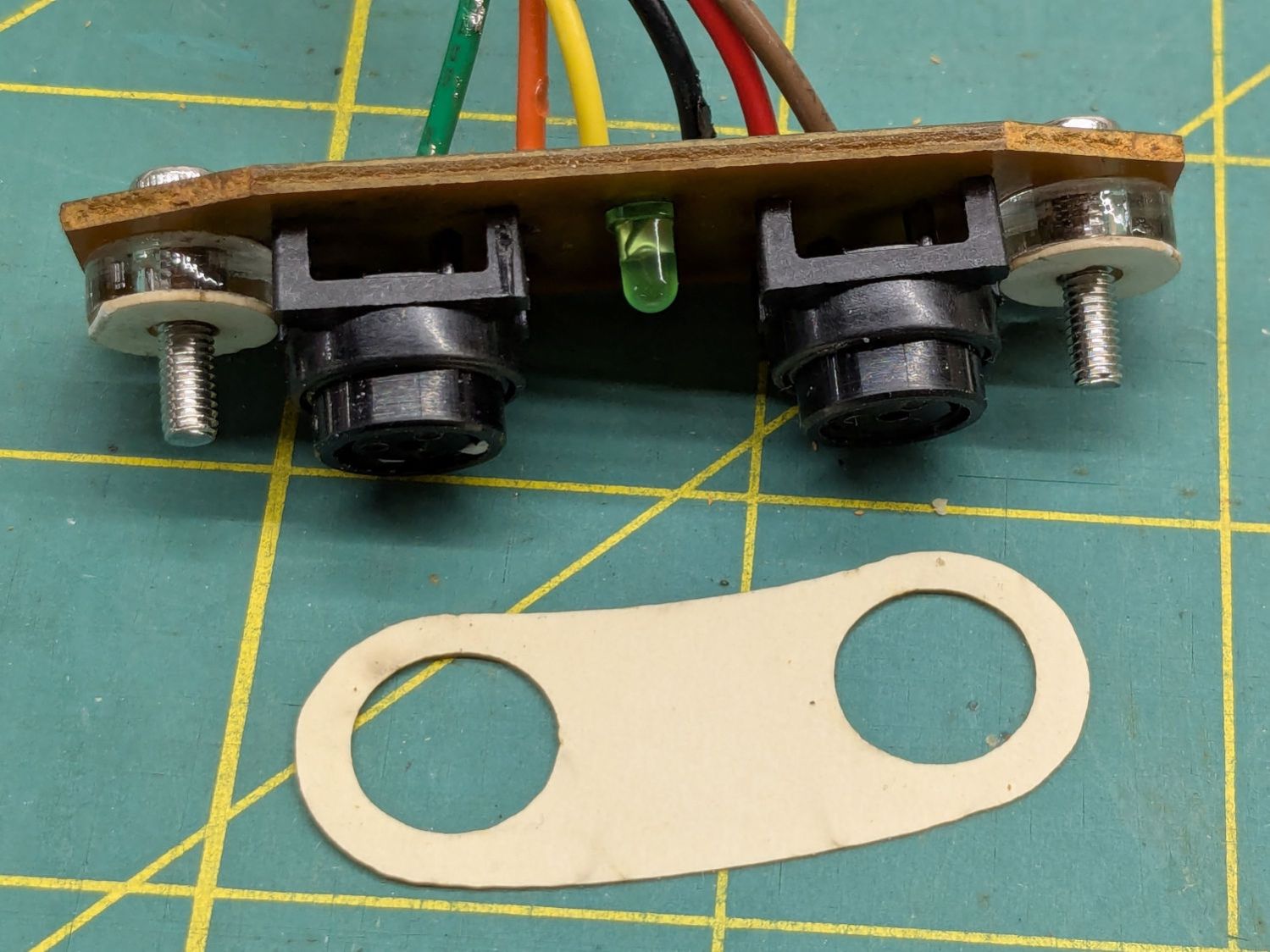
Well, almost perfectly. The original case holes were a snug fit around a 25/64 inch = 9.8 mm drill , so I hand-twisted X and Y drills (10.1 and 10.3 mm, respectively) to embiggen the holes for a loose fit around the new switches.
The two small plastic disks + paper shims hold the PCB just far enough away from the case to put the switch actuators flush with the case surface, with 12 mm M3 SHCS replacing the original 6 mm screws.
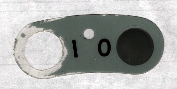
The cardboard test piece came from the usual scan of the original switch cover and, after a few iterations, we now have a stylin’ paper replacement:
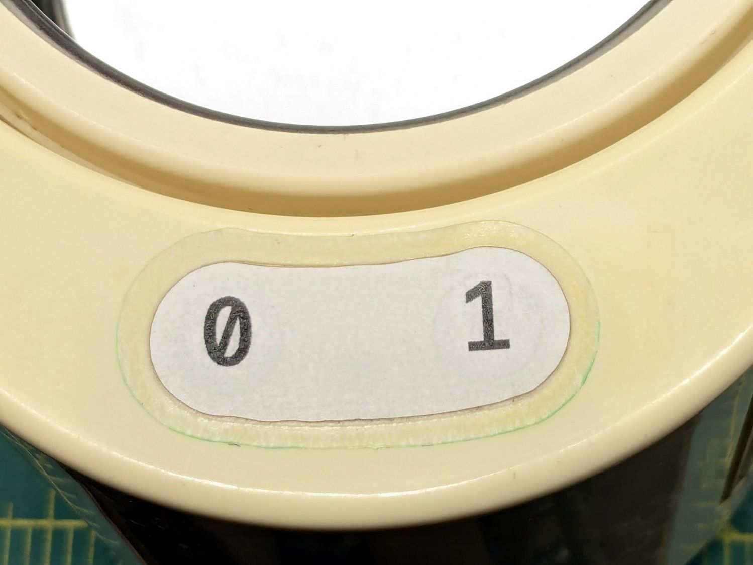
The transparent cover with greenish edges is transfer tape intended for vinyl sheets, which will likely not survive very long at all. It’s outset 3 mm from the paper label, just barely enough to get any traction at all on the case.
While I was at it, I replaced the worn black rubber feet with fancy red stamp-pad rubber feet:
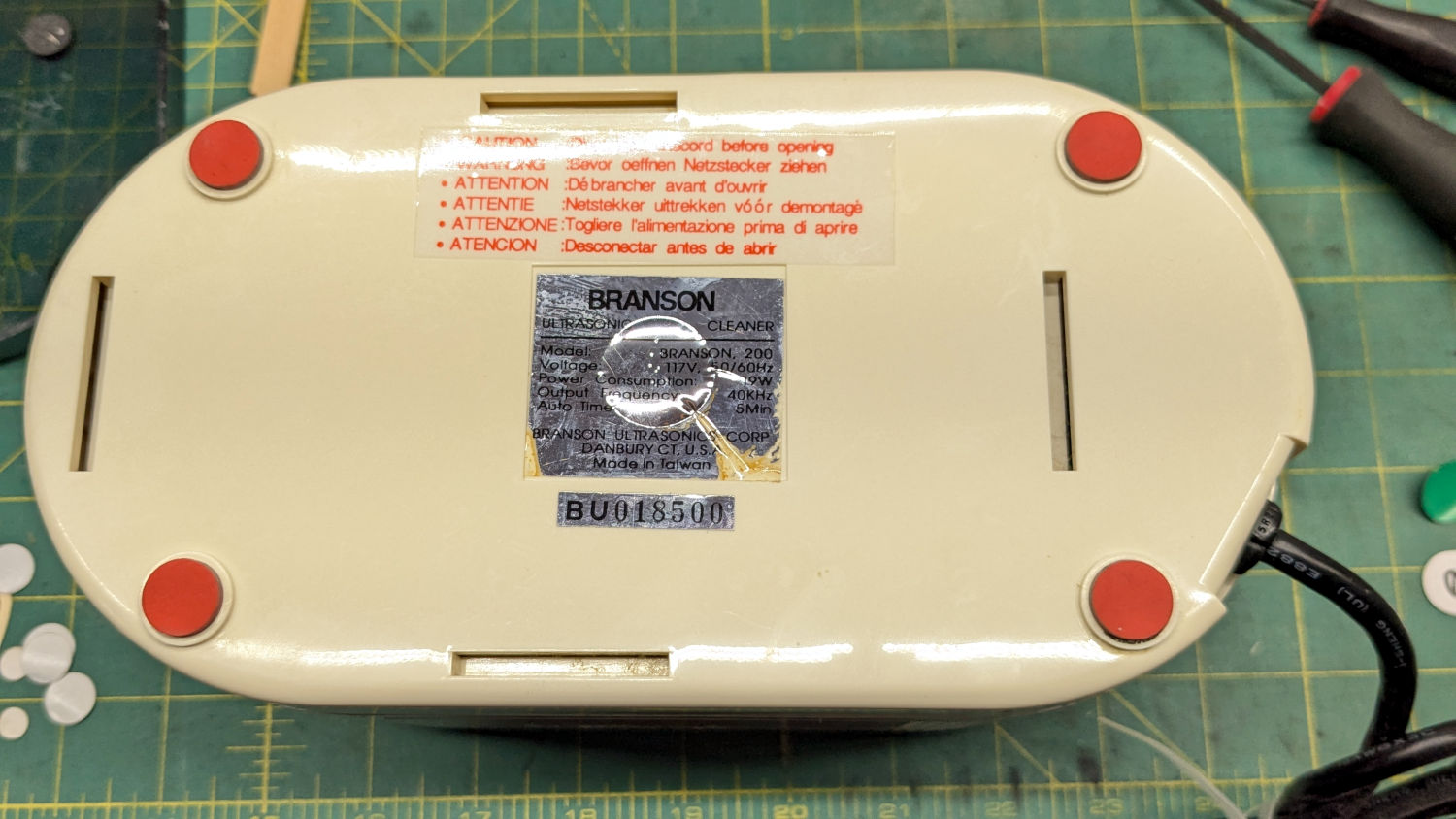
For the record, only two screws secure the top & bottom parts of the case. They’re on the power-cord end of the bottom, so those are the only two feet you must peel off to get inside.
All of which put the cleaner back in operation while I figure out what kind of tape will seal the power switches more permanently.

Comments
5 responses to “Branson 200 Ultrasonic Cleaner: New Switches and Resistor”
..what kind of tape will seal the power switches more permanently.
Overhead transparency film? A piece large enough to cover the whole panel. Which shifts the problem to the glue: Craft/photo tacky spray?
Extra credit: Is the harder plastic used for laser printer transparencies better than the softer sheets? Can you laser cut it if you paint it black? Can you cut it, if you just print a black cut line?
Oh, so much potential to make engaging content for your followers. Just kidding, there are probably entire groups of arduino-kids making front panel covers out of that material. If they know, what a overhead projector is. Probably, they’re using sticky vinyl and a cricut – ooh, another option. Dollar store has some, even glitter.
The original switches had a small round stem and depended on the thick plastic printed label to distribute the finger pressure across the opening. I think the label had a circular embossed / stamped fold line just smaller than the hole, which eventually failed and released the entire button top.
The original cover tape was very thin and very tough to withstand all the flexing around the button hole. Past experience has been with the OEM label, but I can now accurately cut such things and ought to be able to come up with something workable.
Which definitely won’t make me much of an “influencer”.
I can’t make out the vendor for the 555 timer, but the Moto date code looks standard. That would be Week 34 of 1997. (National, Signetics, and HP used the format.) The timer uses something different, but it looks like week 27 of a year ending in 7.
Quick and dirty primer: https://www.instructables.com/How-to-read-date-codes-on-ICschips/
1997 seems much too recent, but I’ve been certain of things that turned out to be absolutely not that way, so my remembery may be kaput. :sigh:
Surprisingly, the power transistors over on the end of the PCB don’t have anything resembling a date code: we know as much as we ever will.
Hey, I have that tee-shirt too! [grin/wince]