The LEDs in each stack light layer require a current sink handling about 50 mA, far above the ability of cheap optoisolators based on the EL817 photocoupler:
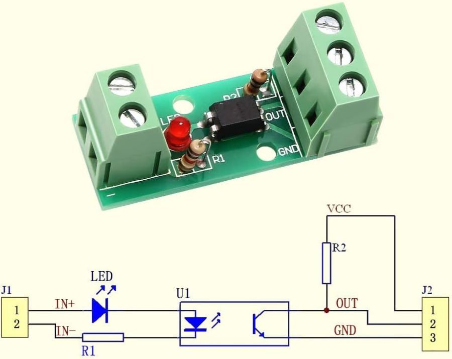
I’ll go into the motivation for optocouplers along with the laser controller wiring details.
As delivered, the PCB has:
- R1 = 1 kΩ (a convenient 1 V/mA current sense)
- R2 = 10 kΩ (a rather high-value pullup)
The idea is to add an able-bodied transistor to the output in a Darlington configuration:
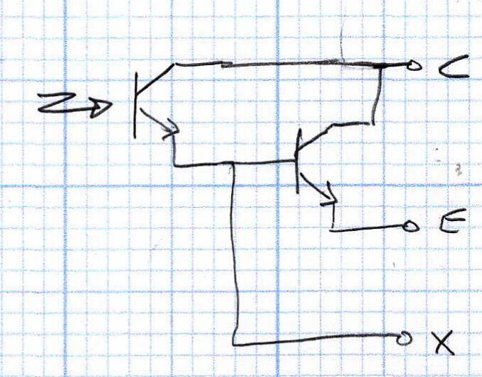
Some rummaging produced a small bag of 2N3904 transistors, although nearly any small NPN transistor will suffice. Removing R2 cleared the field for modification:

The 2N3904 transistor (with the usual EBC pinout) fits face-down under the PCB:

The cross-legged layout conceals the emitter and base leads being soldered snugly to the former OUT and GND terminals, respectively, with the collector going to the VCC terminal. The terminals thus become:
VCC→ CollectorOUT→ EmitterGND→ X (no connection)
Although I have little reason to believe the EL817 chips are anything other than what they claim to be, their topmarks seemed rather casual:

The other four chips carried C333 rank + date codes.
The datasheet says the C means the Current Transfer Ratio is 200% to 400%: the output current should be 2× to 4× the diode current. The test condition are 5 mA into the diode and 5 V across the transistor terminals. A quick test:
- 2 mA → 4 mA = 2×
- 5 mA → 15 mA = 3×
- 10 mA → 35 mA = 3.5×
- 12 mA → 40 mA = 3.3×
The output transistor is rated only to 50 mA, so I stopped at 40 mA. The CTR is between 200% and 350% over that range, suggesting the parts are really real.
The 2N3904 should have an hFE above 60 in that current range and multiply the EL817 gain by about that amount. Another quick test in the Darlington configuration, now with the 5 V supply across the 2N3904:
- 100 µA → 8.1 mA = 81×
- 250 µA → 43 mA = 172×
- 500 µA → 83 mA = 166×
The overall current gain is 40× to 50×, less than the estimate, but plenty high enough for my purposes. If you cared deeply, you’d run a circuit simulation to see what’s going on.
Knowing I needed only 50-ish mA, stopping with the transistor burning half a watt (because VCE is held at 5 V) seemed reasonable. In actual use, VCE will be on the order of 1 V and the dissipation will be under 100 mW.
A quick test shows they work as intended:
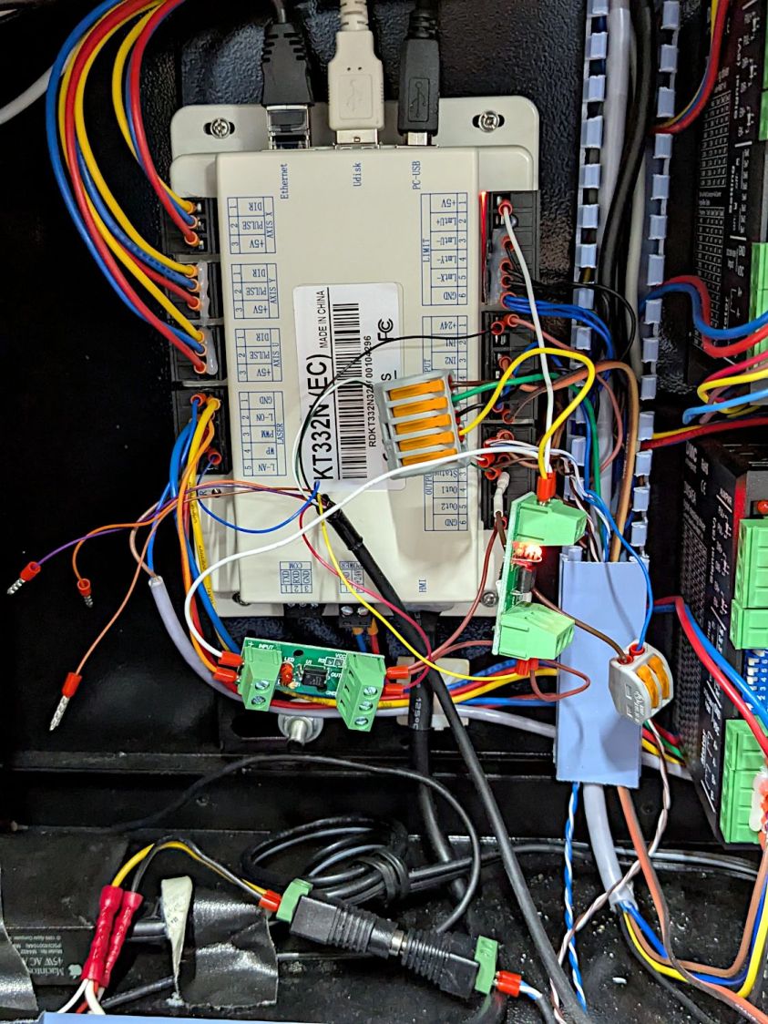
But, yeah, talk about hairballs. Those things cry for little housings to keep them out of trouble.
The chonky lumps with orange stripes are Wago Lever-Nut connectors: highly recommended.

Comments
2 responses to “Stack Light: Optoisolator Boost Transistor”
[…] than let the boosted optoisolators flop […]
[…] as its diode will be off when the L-ON output is high. When it’s low, the diode turns on, the isolator’s output transistors conduct, and the stack light gets the full 24 V it […]