With Mirror 1 moved 10 mm to the right (as seen from the front of the cabinet), Mirror 2 must move 5 mm to fix the problem that started this whole thing and put the beam in the center of the mirror:
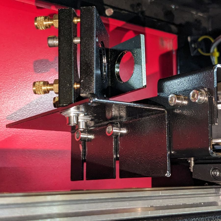
This puts the bracket holding Mirror 2 closer to the center of its x axis adjustment range:

Remember, the flange is fixed to the gantry and the bolts move with the mirror mounting bracket.
Raising the laser tube by 5 mm requires Mirror 2 to go upward by a bit to put the beam at the center:
The least awful way to make simultaneous X and Z axis adjustments seems to be by feel. Tighten the screws just enough to prevent the bracket from moving easily, then slide it while aligning the top edge with respect to the flange on the gantry.
When it feels about right, stick a target to the aperture, fire a pulse, check the results, and iterate until it is actually right.
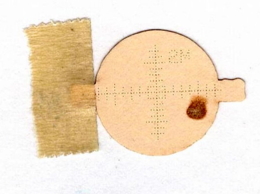
The two screws holding the mirror mount to the bracket sit in slots allowing some adjustment in the Y axis, as well as a slight amount of rotation. AFAICT, the mount was rotated enough that the test pulses passed through the center of the aperture, but hit the mirror off-center as shown in the top picture. I aligned the aperture parallel with gantry, which should put the holder at 45° to the beamline, and hoped for the best.
With the pulse mostly centered, twiddle Mirror 1’s alignment to make the beam parallel to the Y axis, which eventually produced these results, with each target getting a pulse at each end of the Y axis travel:
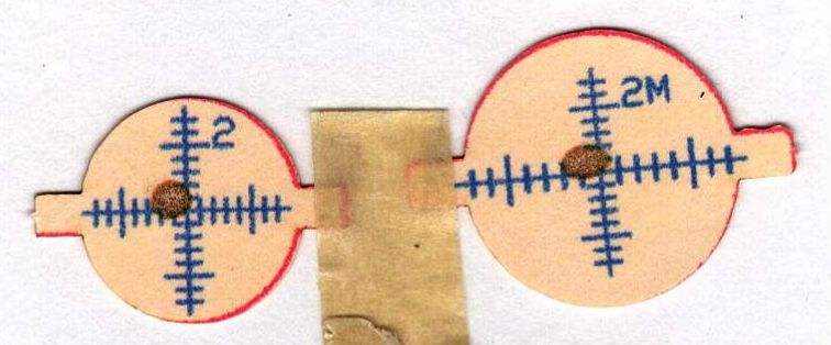
Not perfect, but much better than where it started.

Comments
One response to “Laser Cutter: Moving Mirror 2”
[…] Mirror 1 and Mirror 2 aligned, the next step is positioning the laser head to put the beamline at the center of both the […]