Raising the laser tube 5 mm required nothing more than cutting and inserting 5 mm spacers and finding slightly longer M4 screws:
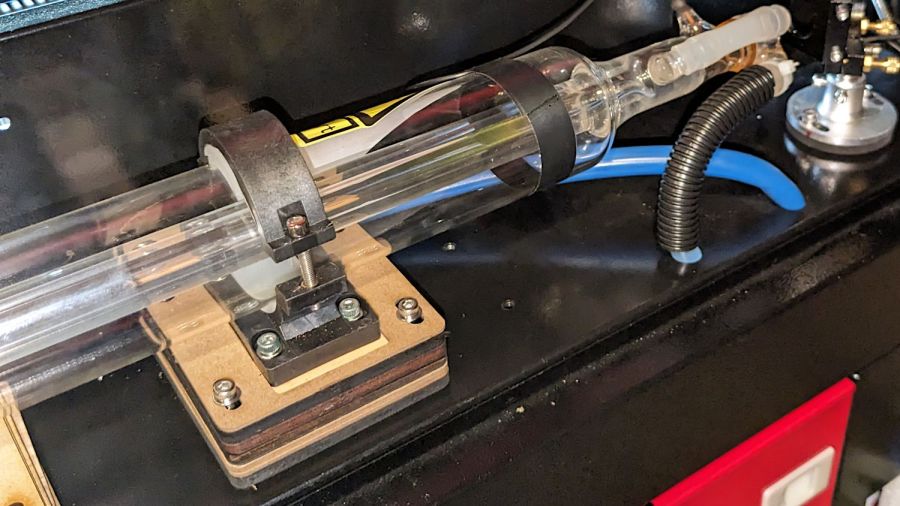
I used an ancient adjustable inside caliper to put the tube the same distance from and aligned parallel to the partition.
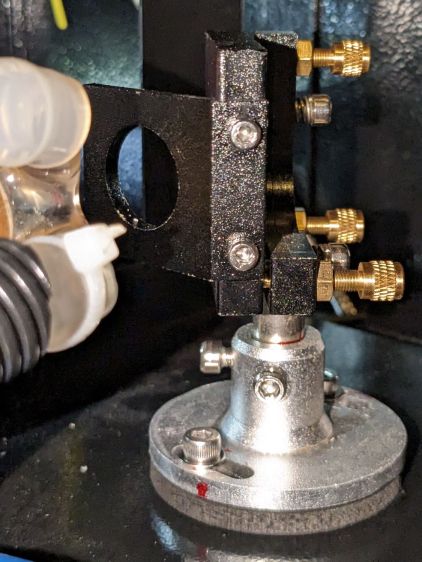
Sliding the tube an inch to the left provided enough space to drill & tap two new holes for the Mirror 1 mount to move the beamline 10 mm along the X axis:
I briefly considered crunching rivnuts in there, but the mirror mount expects to sit flat on the floor with no room for rivnuts. So it goes.
Although Mirror 1’s mount has some vertical adjustment, the central stem was already close to its maximum extension, so I cut a 5 mm plywood pad to raise the base:
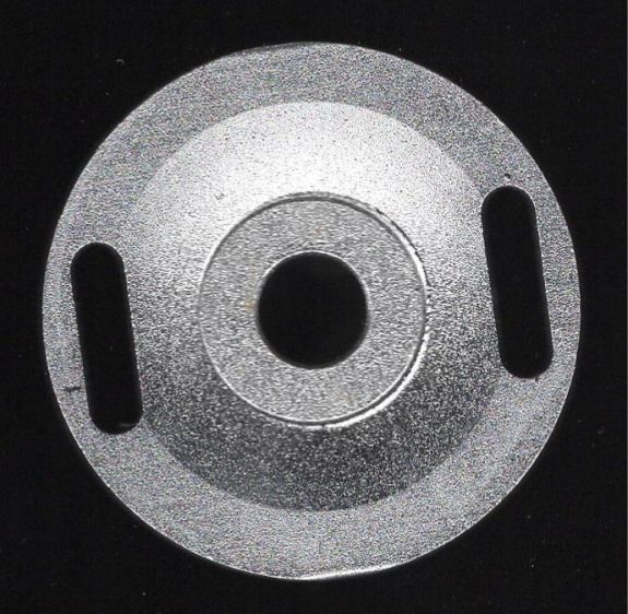
Despite what the lighting suggests, it’s concave. The image was clean and contrasty enough to just trace into vectors with LightBurn, then Fire The Laser to cut the spacer:
If you’re wondering how that worked with the tube jacked up, Mirror 1 sitting on the scanner, and the beamline in disarray, there’s considerable benefit in doing things out of the obvious narrative sequence.
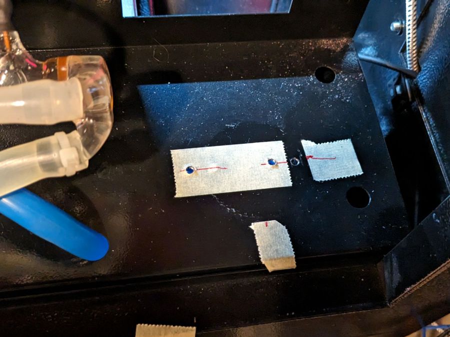
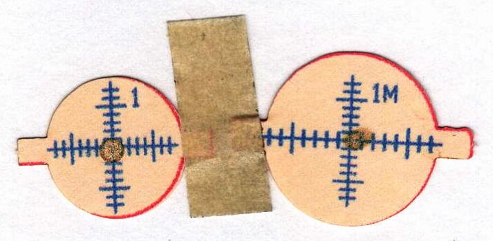
Reassemble the mirror, square the entrance aperture to the partition, fire a couple of test shots to center the mirror on the beamline:
And that part’s done.

Comments
2 responses to “Laser Cutter: Moving Mirror 1”
[…] Mirror 1 moved 10 mm to the right (as seen from the front of the cabinet), Mirror 2 must move 5 mm to fix the problem that started […]
[…] Mirror 1 and Mirror 2 aligned, the next step is positioning the laser head to put the beamline at the center […]