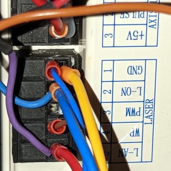
As before, with the Ruida KT332N controller’s L-AN analog output connected to the HV power supply IN terminal:
This time the scope traces include both the controller’s output voltage and the laser tube current:
The traces:
- 1 X axis
DIR, low = left-to-right (yellow) - 2
L-ONlaser enable, low active (magenta) - 3
L-ANanalog voltage (cyan) - 4 tube current – 10 mA/div (green)
At 50 mm/s = 50 Hz both the L-AN analog voltage and the laser current hit full scale:
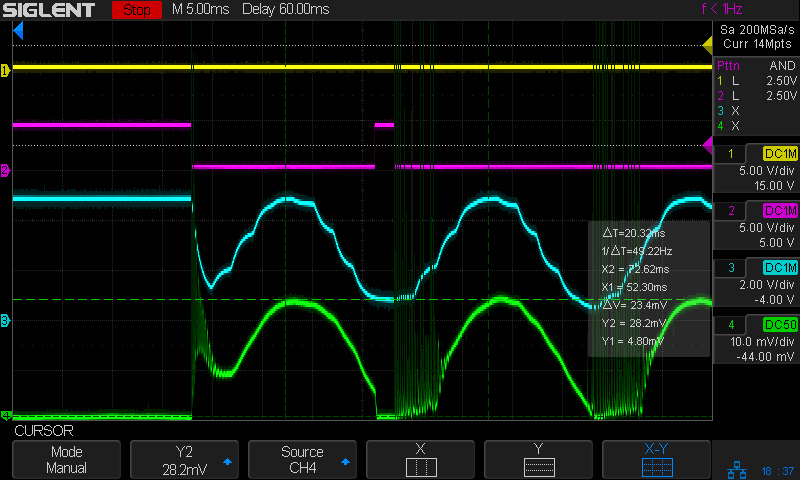
The laser current resembles a damped RLC oscillation when started at nearly full scale and is entirely chaotic when started from zero, but behaves reasonably well for the rest of the cycle.
The power supply’s current bandwidth is definitely smaller than the controller’s voltage bandwidth, as shown by all those sampling steps simply vanishing.
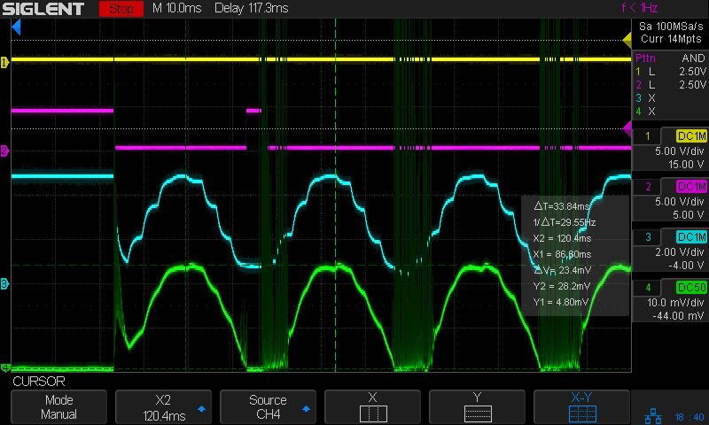
As expected, at 200 mm/s = 200 Hz the L-AN analog voltage is down 3 dB:

At that frequency the tube current is down 8 dB, from 23.4 mApp to 9.4 mApp, showing how much the power supply’s PWM filter contributes to the rolloff. Since we’re interested in the overall bandwidth, the tube current is down 2.4 dB to 17.8 mA at 100 Hz, suggesting the -3 dB (16.6 mA) frequency is just slightly higher:

However, I think that’s the wrong way to calculate the -3 dB point of the laser power, because the tube operates at essentially constant voltage, which means both the analog voltage and the tube current are linearly related to the laser tube power, rather than being proportional to its square root.
If that’s the case, then the analog output voltage is down by ½ at 300 Hz and the tube’s half-power point occurs at 23.4 mA/2 = 11+ mA, closer to 200 Hz than 100 Hz. Given the resolution of the measurements, this doesn’t make much difference, but it’s worth keeping in mind.
Applying a 100 Hz PWM pulse (thus, a sharp step) to the power supply shows the laser tube current has a risetime (and falltime) around 2 ms, about what you’d expect from a single 200 Hz lowpass filter inside the power supply:

As far as I can tell, the controller’s “analog” output is just its digital PWM output passed through a 200 Hz low-pass filter. It would be useful as an analog input to a power supply without an additional PWM filter, but combining those two filters definitely cuts the overall bandwidth down.
All of the measurements as a slide show:
Tube Current – analog bandwidth – 10 sine – 25mm-s – 10mA-div – 254dpi Tube Current – analog bandwidth – 10 sine – 50mm-s – 10mA-div – 254dpi Tube Current – analog bandwidth – 10 sine – 100mm-s – 10mA-div – 254dpi Tube Current – analog bandwidth – 10 sine – 200mm-s – 10mA-div – 254dpi 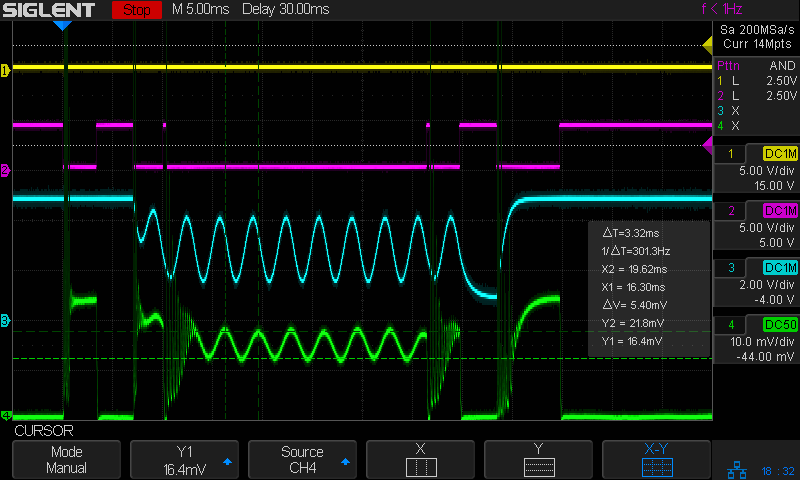
Tube Current – analog bandwidth – 10 sine – 300mm-s – 10mA-div – 254dpi 
Tube Current – analog bandwidth – 10 sine – 400mm-s – 10mA-div – 254dpi 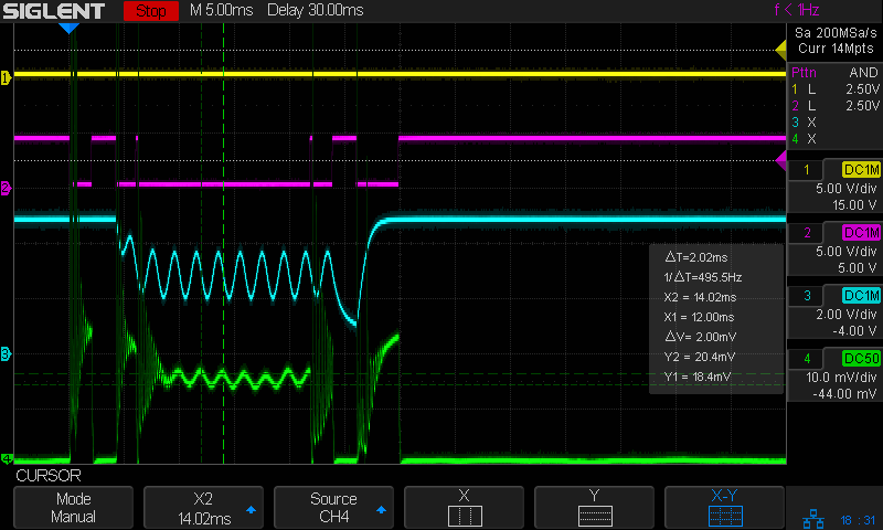
Tube Current – analog bandwidth – 10 sine – 500mm-s – 10mA-div – 254dpi
To round this out, I must measure the laser tube current bandwidth using the controller’s PWM signal. Because PWM passes through only the power supply’s lowpass filter, the bandwidth should be slightly higher.
Overall, though, the bandwidth seems surprisingly low.

Comments
3 responses to “CO₂ Laser Tube Current: Analog Bandwidth”
Silly question probably, but why didn’t/don’t you reverse engineer the PSU circuit to see what it is actually doing? I must have missed something. Sorry.
Good question!
Basically, I’m more interested in how the controller + power supply behave than why, mostly because I don’t see much opportunity for any internal changes. I’ll leave it to somebody else who’s oppositely interested to rummage around inside and figure out what’s going on in there.
[…] bandwidth measurements in hand, a semilog plot with eyeballometric line fitting makes the conclusion […]