Ed Nisley's Blog: Shop notes, electronics, firmware, machinery, 3D printing, laser cuttery, and curiosities. Contents: 100% human thinking, 0% AI slop.
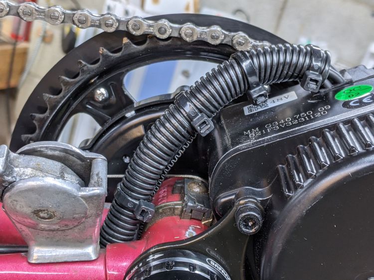
With the Bafang BBS02 and all its gimcrackery on the Terry Symmetry buttoned up and ready to go, I took a few closeout pictures for future reference.
The motor has a sheaf of wires sticking out of the bottom crying out for a protective covering:
Bafang BBS02 – wire bundle cover
Although cameras tell only the truth they’re allowed to see and can be made to lie by omission, sometimes their latent truth was completely invisible to eyewitnesses in real time.
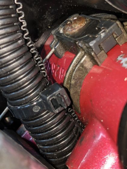
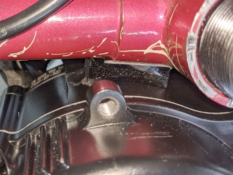
I only noticed the mis-routed shift cable when I looked through the last set of pictures.
It should pass through the plastic channel under the metal tab holding the cable guide to the bottom bracket shell:
Bafang BBS02 – wire bundle vs shift cable
Normally, aiming the cable into the channel is no big deal. In this case, I had to undo the shift cable, remove the left crank, loosen the motor and rotate it out of the way, nudge the cable with a small screwdriver, then reinstall in reverse order.
The original BBS02 reaction spacer for Gee’s Terry Symmetry didn’t work quite the way I expected:
Bafang BBS02 – reaction block displacement
The motor evidently vibrates enough to propel the block forward, shearing the double-sticky foam tape which was never intended to resist force in that plane. I thought the block was located at the point where the motor casing was tangent to the frame tube, so as to equalize the forces in both directions, but … nope.
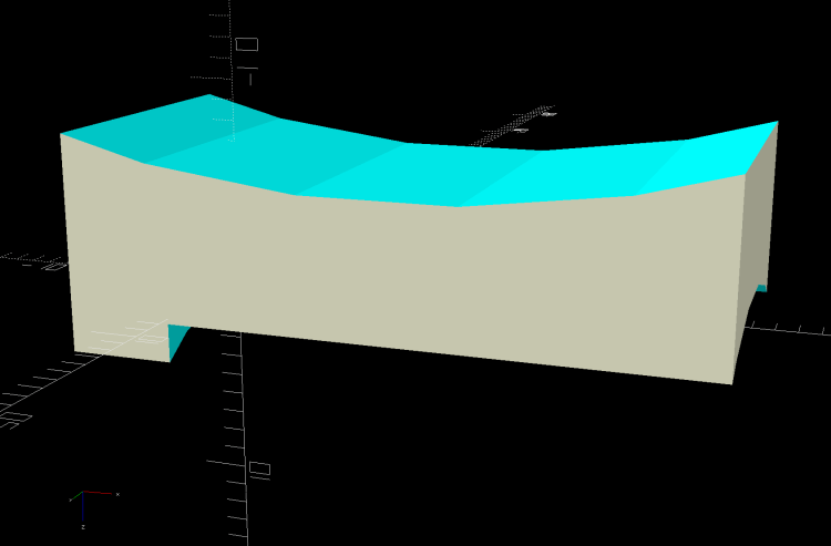
A revised design based on measurements informed by new knowledge:
Terry – Bafang motor spacer – improved – solid model
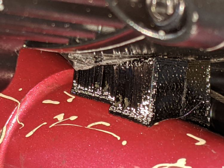
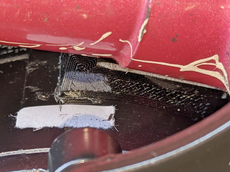
The upper curve is now symmetric and the whole block mounts more rearward under the bottom bracket lug, where some tedious work with a machinists square located the real tangent point:
Bafang BBS02 – reaction block improvement
The motor sure doesn’t look like it’s tangent, but a dry fit showed all the curves laid against the case and tubes.
The brazing fillet means the step fitting the downtube can’t sit snug against the edge of the lug, but most of the reaction force should go through the section into the lug, near the center of the block.
A crude marker will keep track of any motion:
Bafang BBS02 – reaction block marker
I think the symmetric curve against the motor has enough projection to keep the block from wandering off, even if I haven’t gotten the location exactly right.
A gusty thunderstorm knocked out power across Dutchess County, including half the service to our house. Being glad the refrigerator and freezer were on the live phase, I shut off the affected breakers on the dead phase, as well as all the 240 V breakers, and, with the living room darkened, we skipped our evening storytime.
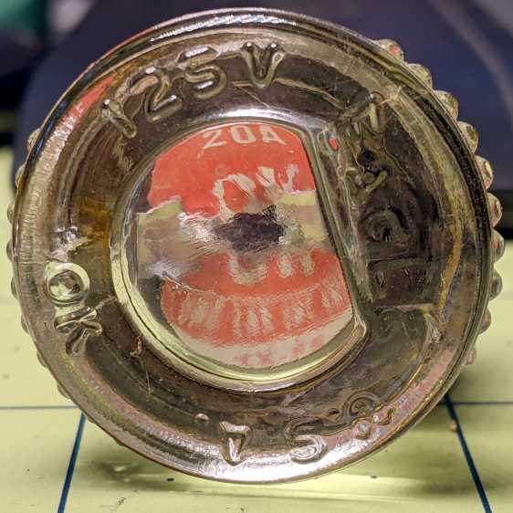
By the next morning, a quick lamp test showed the recloser out on the pole had worked its magic, so I flipped all the breakers back on. The living room remained dark, prompting an investigation of the fuse box feeding the original house wiring:
Given what happens while wind and falling branches knock power lines askew, anything is possible. I have no idea where the fault current went, but replacing the fuse brought the living room back to normal.
None of the various UPS / lamps / phones seem damaged; I admit not peering inside the outlets to check for arc damage.
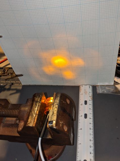
The truck side marker lights I’m thinking of using as daytime running lights have a pentagonal lens, so they should have a pattern with a bright central beam surrounded by five lobes. The one on Mary’s Tour Easy produced an oddly shaped blotch on the garage wall, so I ran the others though a simple test setup:
Side Marker – beam test setup
The lights sit horizontally in a small vise to keep them level and in the same position, although in no particular rotational orientation, and 100 mm from the graph paper. It’s running at 6 v to keep the brightness down enough to avoid blowing out the image. All of the images were exposed based on the central spot, so the surrounding paper gives some idea of the relative brightness: darker paper = brighter LED spot.
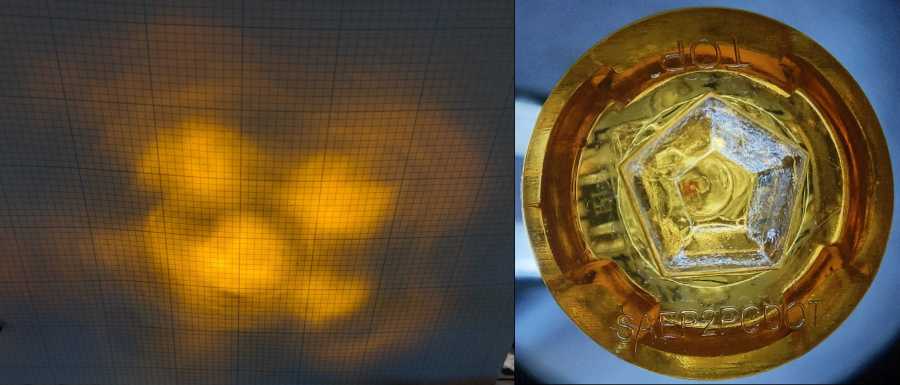
The front view of the lights comes from the stereo zoom microscope, with the wires gripped in a Third Hand and rotated to put the (inverted) TOP label where you’d expect it. They’re all roughly at the same position and pretty nearly lined up with the lens axis. The bubble-looking thing behind the central pentagon is the lens on the Piranha LED package, which should be centered but rarely is. You can see the dark orange square of the amber LED chip in some of the pictures.
Without further ado, the nine truck side marker lights that aren’t on her bike:
Side Marker – beam test – A
Side Marker – beam test – B
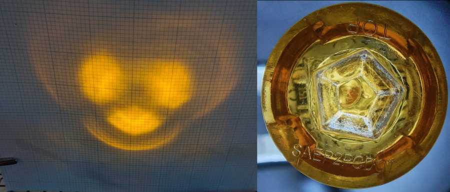
Side Marker – beam test – C
Side Marker – beam test – D
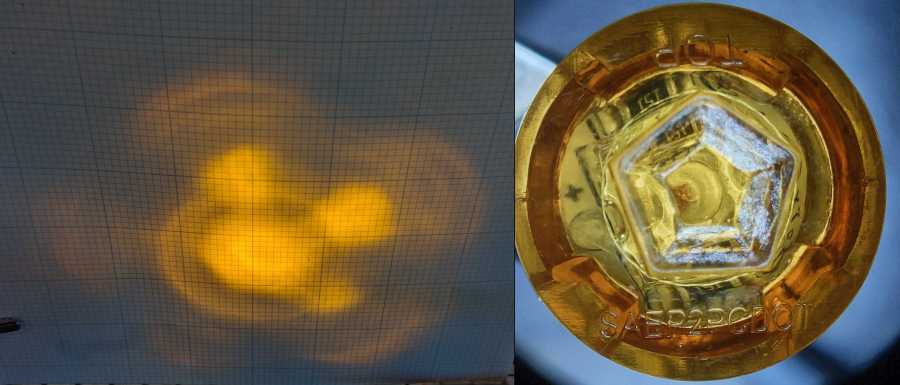
Side Marker – beam test – E
Side Marker – beam test – F
Side Marker – beam test – G
Side Marker – beam test – H
Side Marker – beam test – I
Side Marker Light – Beam tests
Side Marker E has a blob that looks like a cataract atop the LED lens, but it might be a mold imperfection.
Obviously, paying a buck a light doesn’t get you much in the way of build quality these days.
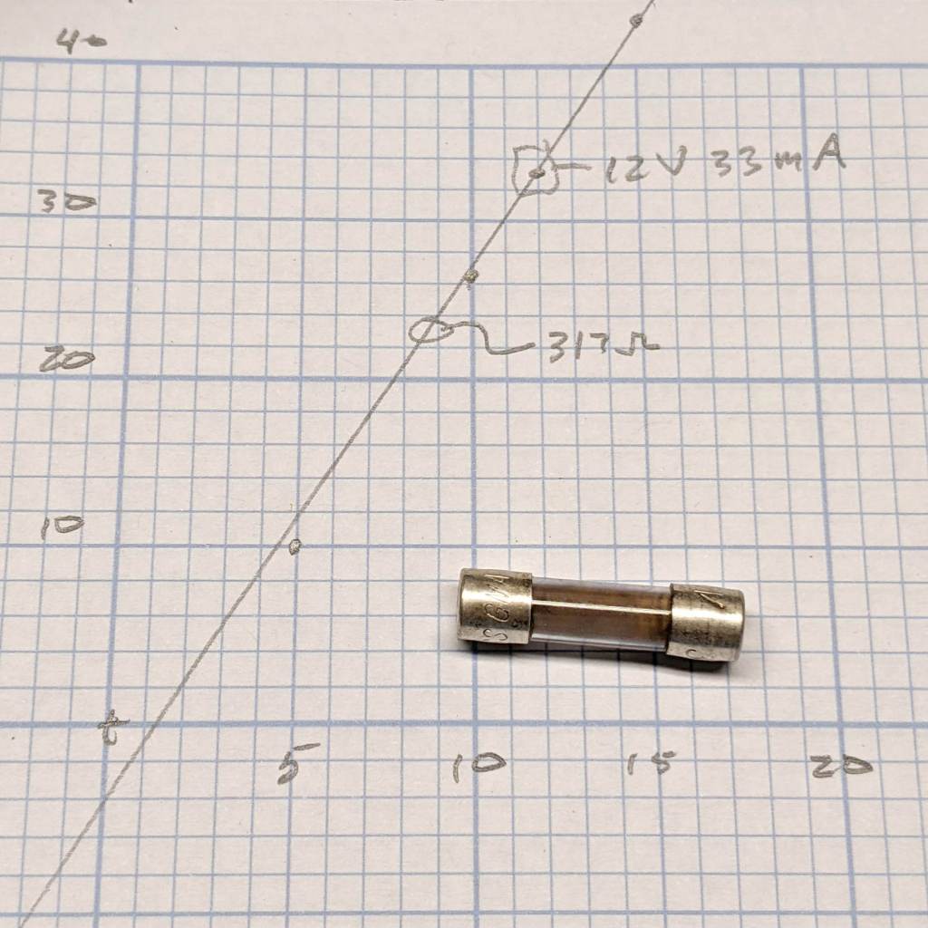
The slope suggests a 330 Ω resistor, but the internal PCB sports a pair of 150 Ω SMD resistors.
I don’t believe the X-axis intercept for a moment, but 1.5 V seems about right for an amber LED.
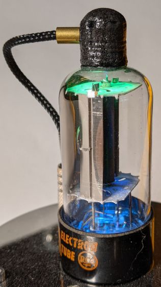
Oh, and the DMM fuse doesn’t have a ceramic body. You’re seeing the vaporized remains of a 315 mA fuse neatly deposited over the inside of the glass tube after being shorted across a 3 A bench supply.
I hate it when that happens. Replacing it emptied the little bag of those meter fuses; next time it’ll get a half amp fuse.