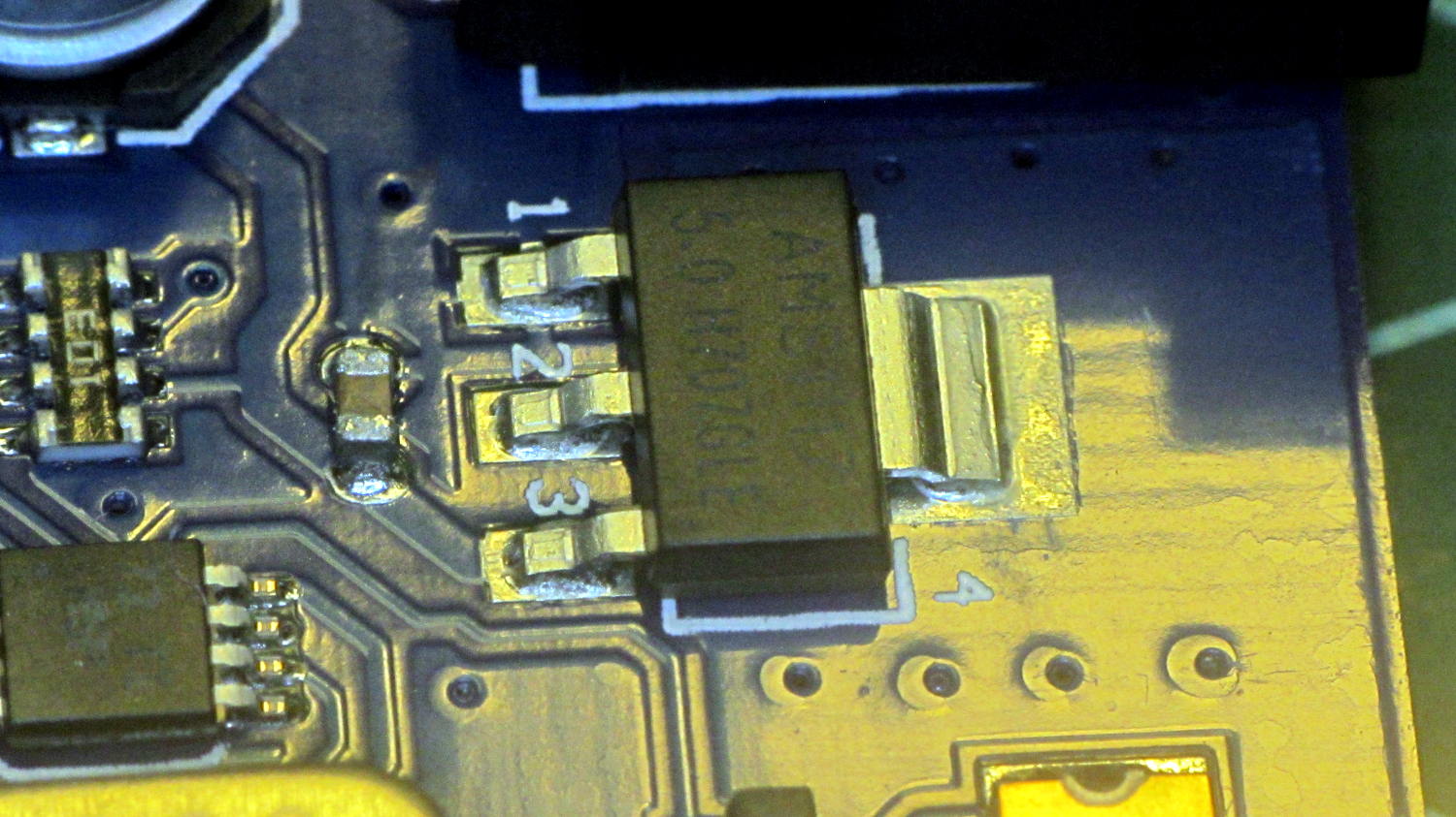
The knockoff Arduino Mega board actually has eight thermal vias on the copper pour around the regulator:
I sawed up a clip-on heatsink originally intended for a 14 pin DIP, bent it a bit, and epoxied it atop the regulator with enough of a blob to contact the copper pour:

That’s metal-filled JB Weld for good thermal conductivity and electrical insulation:
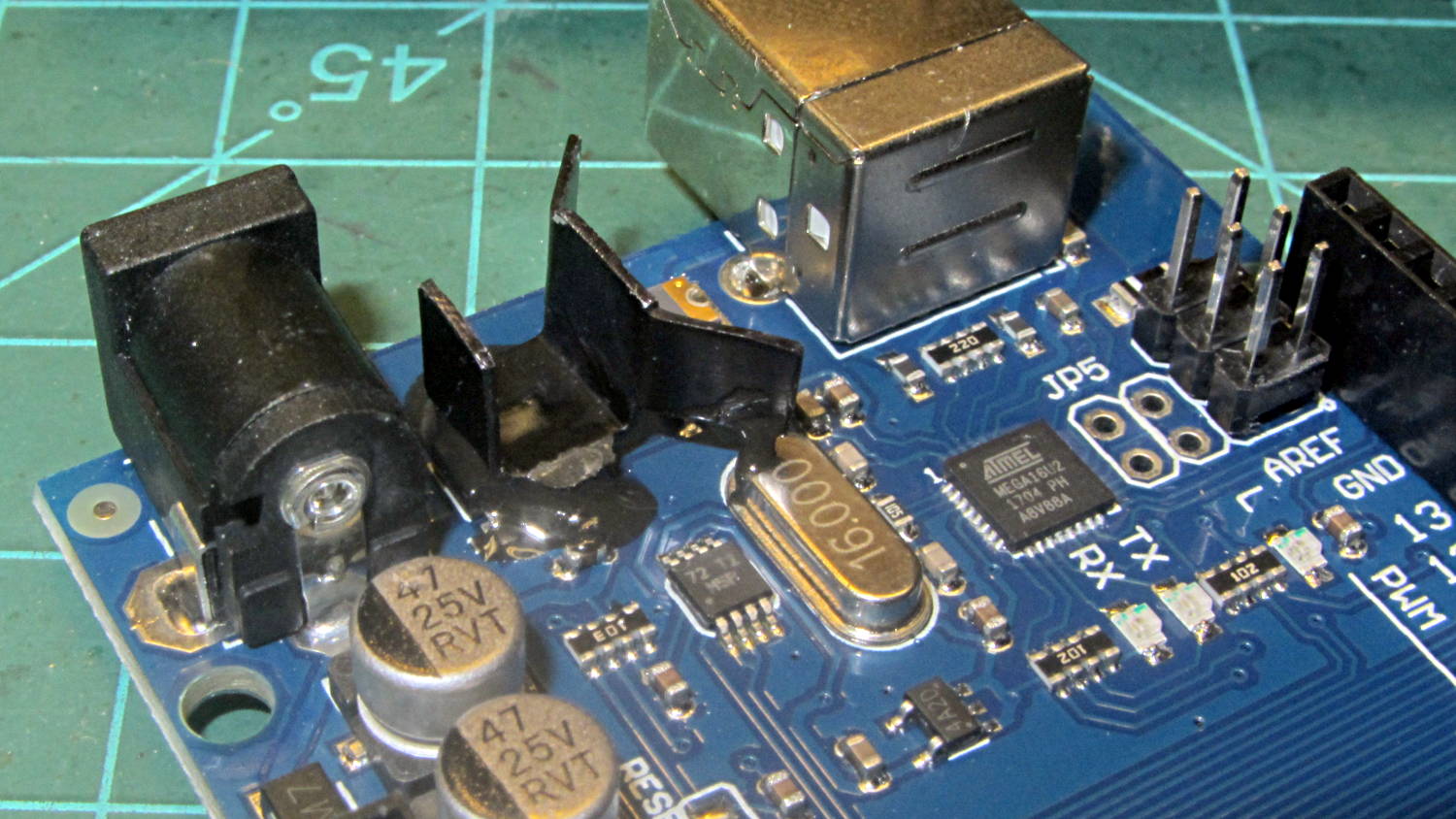
The blob affixing the heatsink to the crystal can was an oopsie, but won’t do any harm. It’s not clear the heatsink will do any good in that confined space, but those regulators lead a rough life and need all the help they can get.
The five stepper drivers sport HR4988SQ chips, rather than Allegro A4988 chips:

I’d rather see a knockoff than a counterfeit, although by now there’s really no way to tell if it’s a counterfeit knockoff. The Kynix datasheet looks like a direct rip from Allegro.
They now sport cute little heatsinks, which, for all I know, might help a bit:
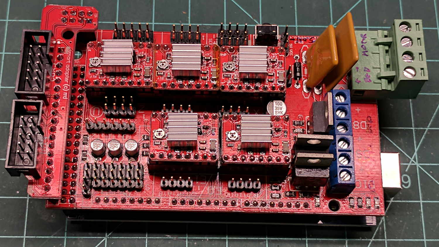
The driver boards are slightly longer than the spacing mandated by the continuous socket strips under the three-in-a-row layout:

Introducing them to Mr Disk Sander (turned by hand) knocked off just enough to make ’em fit.

Comments
8 responses to “RAMPS 1.4 Heatsinking”
JBWeld is electrically non-conductive? That sounds very useful.
Indeed! Each little metal particle (dust, really) sits inside an epoxy resin coat: more thermally conductive than pure resin and an electrical insulator.
Affixing SMD LEDs to a heatsink worked perfectly: https://softsolder.com/2015/01/06/kenmore-158-led-heatsink-epoxy-sculpture/.
I kept the aluminum heatsinks off the capacitors & suchlike around the chip, even though aluminum oxide should be nonconductive. If the drivers emit magic smoke, then I was wrong again.
Aluminum oxide (I’m assuming the anodized variety) can be thin enough to get breakthrough, especially if something scratches it. Pinholes are also an issue unless care is taken to eliminate them. I don’t recall the thickness of native room-temp oxide, but it’s pretty thin.
I wanted JB Weld to be conductive (wanted to connect a ground to a well casing, and my gas rig didn’t have enough heat), so was rather disappointed that it didn’t. I ended up with ground rods for that well. For the new well, I drilled and tapped for a ground point on the casing. The old well didn’t really have enough room to swing a tap wrench… The extra ground rod got used a) for insurance, b) because I had one sitting around, and c) the soil in that area was actually easy to drive rods. Unlike the shale hardpan we have on the ridges.
I’ve used silver epoxy for microcircuits, but I wasn’t going there for a well.
I’m assuming those cute little heatsinks actually have a clear anodized surface, but they may well be bare aluminum with whatever oxide grew in the tumble finishing operation.
Silver epoxy: sounds like a precious metal investment!
Short shelf life investment. Pre-mixed and stored in the ‘fridge.
My method FWIW is to apply a small blob of heatsink grease to the top of the device, put the heatsink exactly where I want it on the device and then run epoxy all around – usually down into the device legs and up onto the heatsink.
Maxes the heat transfer and gives a good mechanical bond – and if I use one of the 5 minute versions of epoxy, it can usually be detached if necessary.
I like it: both fussier and messier than my blobs! [grin]
Given that the main heat transfer path is into the PCB through the big pad on the bottom of the die, anything attached to the chip epoxy looks like fine tuning, so there’s likely no meaningful difference in heat transfer, regardless of what’s between the chip and the heatsink. As long as it’s not air, anyway.
Thanks, high praise!
in my edge-of-specs use of a pair of A4988 modules, I unsoldered the pins and reinstalled them so that they stick out of the top leaving the main thermal path fully exposed at the bottom. This was then smeared with heatsink grease and clamped to a raised block machined in an aluminium block with a 3D printed widget designed to ensure that the A4988 pins didn’t touch the block (don’t ask why I went to this effort…), and the whole clamped down with a narrow plastic based strip allowing access to the trim pot. Lots of effort but I am running 42V at 2.2A and only one failure so far (self inflicted).