Ed Nisley's Blog: Shop notes, electronics, firmware, machinery, 3D printing, laser cuttery, and curiosities. Contents: 100% human thinking, 0% AI slop.
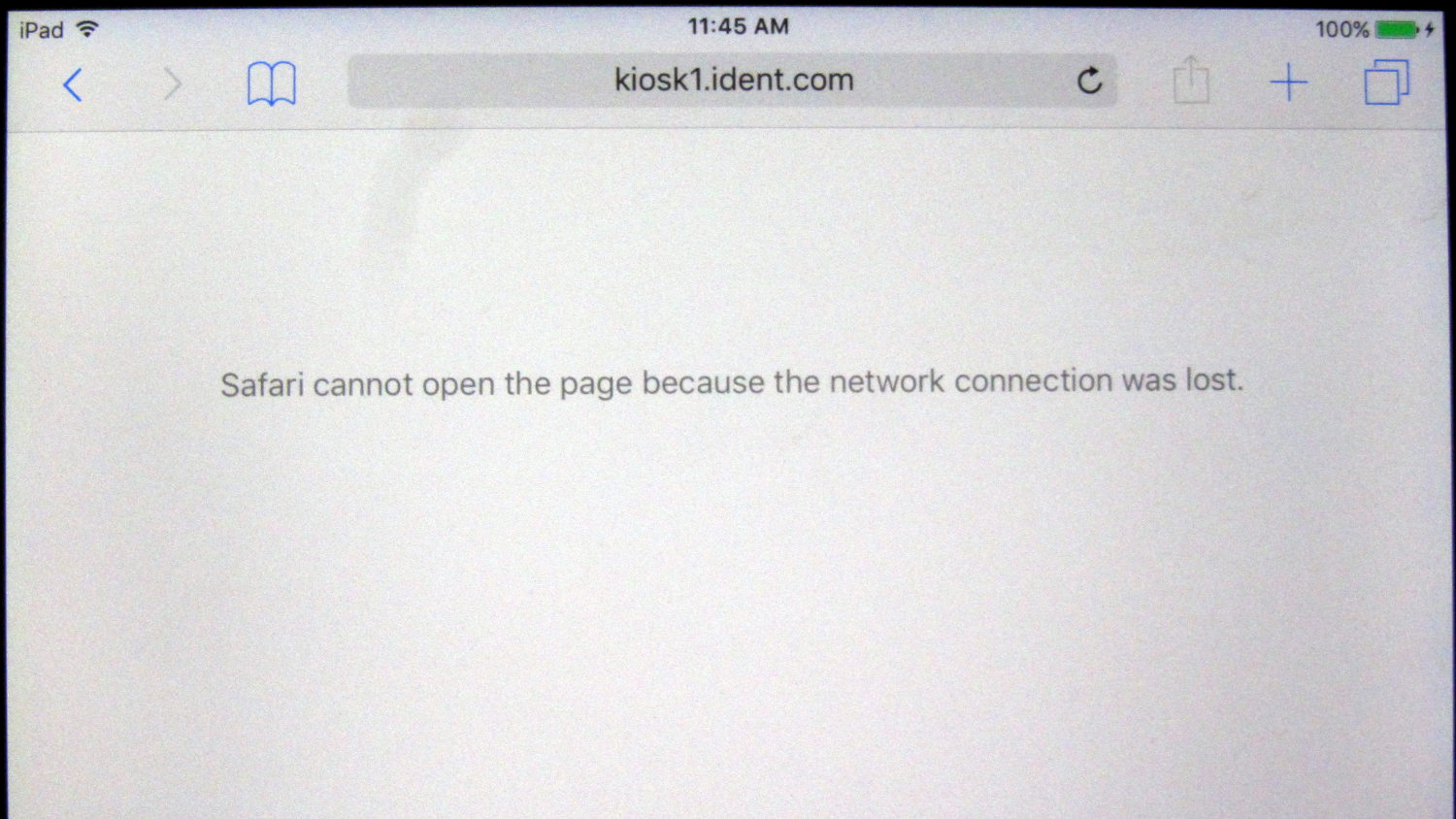
You’ll note the signal strength indicator in the upper left shows as much RF as one might reasonably expect from a router within line-of-sight across the room.
FWIW, I’m getting really tired of the hipster dark-gray on light-gray design ethos.
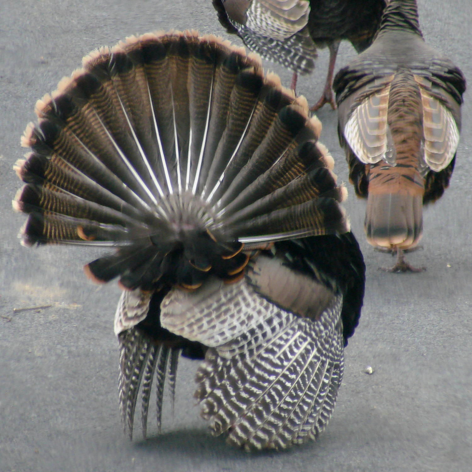
Early spring brings out large turkey flocks and provides a window into their otherwise rather private lives.
Despite all the strutting and posturing by the males, the ladies call the shots. When we see a hen go hull-down like this, we know what’s about to happen:
Turkey mating – invitation
Getting into the right position seems remarkably awkward and requires some cooperation:
Sculptors build figures with aluminum armature (*) wire, because it’s dead-soft, bends easily, and holds its shape:
Armature Wire assortment
The sizes: 1/4 inch, 3/16 inch, 1/8 inch, 1/16 inch. The latter came from my Big Box o’ Specialty Wire, with the others from Richeson via Amazon. You can certainly get better prices for larger quantities from metal suppliers.
1/4 inch wire is way too rigid, although a stalk might hold a display
The 1/8 inch wire looks much different than the others
1/16 inch wire may work better inside a braided sheath with the LED conductors
The wire is probably a 1000-series alloy, if only because anything else would start out too stiff and work-harden too quickly, although the sharp bends in the coils already feel hard. It’s possible to anneal aluminum by hand with some soap and a torch, with meltdown an ever-present hazard. Other references suggesting soaking at temperatures in the 300-400 °C range in a furnace I don’t have.
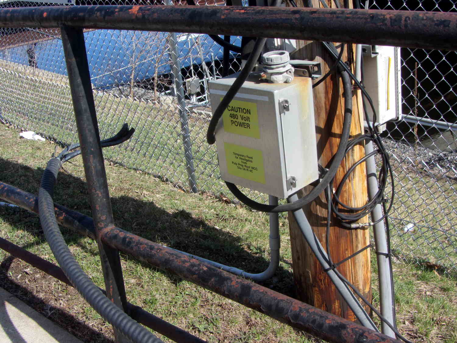
The armored cable draped over the fence probably came from the gland at the top of the box, which now sports a blocking plate that might actually be weatherproof. It had taped-over ends and I assume it fed something downstream that’s now disconnected; the far end of a large loop to the right burrows underground along the sidewalk.
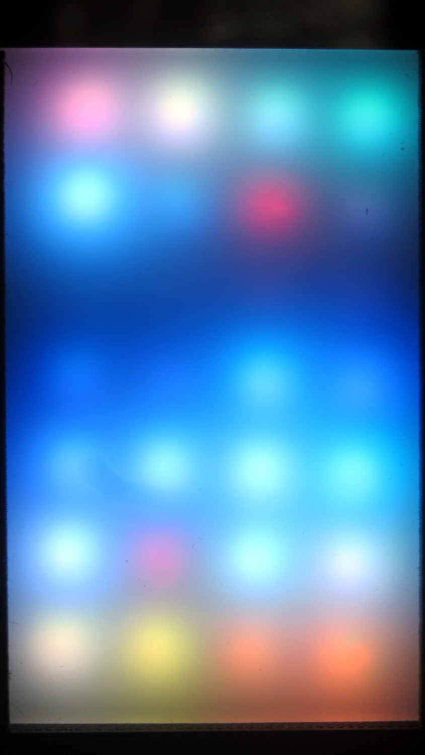
The red pixel in the second row from the top sends pinball panic to the six downstream LEDs (left and upward). Of course, it’s not consistently bad and sometimes behaves perfectly. The dark row below it contains perfectly good LEDs: they’re in a dark-blue part of the cycle.
The first WS2812 failed after about a week. This one lasted 7 weeks = 50-ish days.
The encapsulation seal went bad on this one and, for whatever it’s worth, the remainder still pass the Sharpie test. Perhaps the LEDs fail only after heat (or time-at-temperature) breaks the seal. Assuming, equally of course, the seal left the factory in good order, which seems a completely unwarranted assumption.
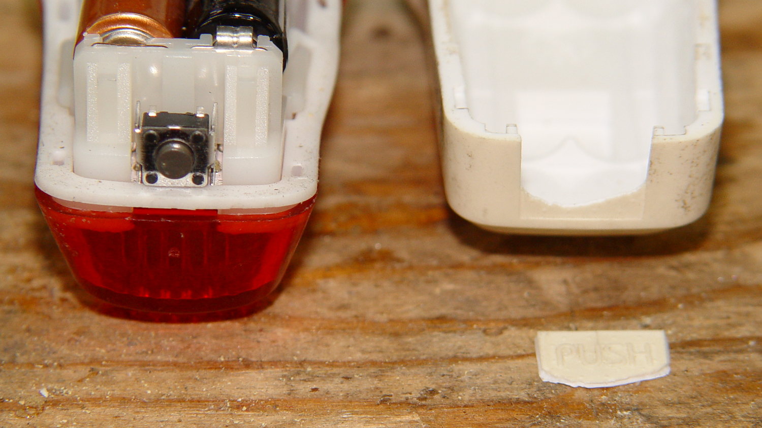
The blinky light on Mary’s bike became intermittent and, after a week or two, I figured out why:
Planet Bike Superflash – fatigued PUSH
The white plastic case has a thin section labeled PUSH over the switch. After five years of exposure to the sun (it faces upward on her bike) and upwards of 2000 pushes (5 years x 200 rides/year x 2 pushes/ride), the edges of that little plate cracked, it slipped inward, and jammed the switch button.
I swapped it for the one on my bike, which mounts with the switch downward and has seen much less use since I began running the Fly 6 rear camera + blinky light, and it was all good.
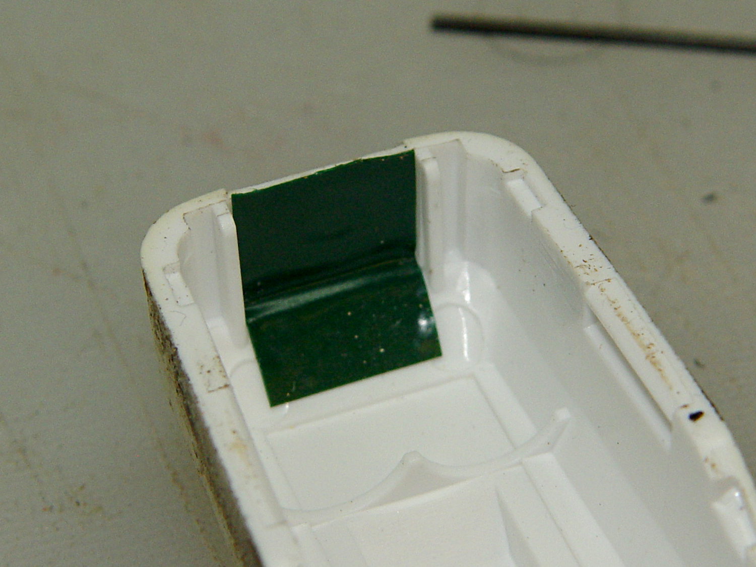
The fractured plate slid snugly back in place, a few drops of IPS 3 solvent-bonded the broken edges, and a snippet of good 3M electrical tape inside the case should provide a bit of reinforcement:
The general idea is to build a specialized sine-wave source as part of a test fixture to measure quartz crystal / tuning fork resonators in the 10 kHz to 100 kHz band. AD9850 / AD9851DDS modules are cheap & readily available, albeit with crappy two-layer PCB layouts and no attention to signal integrity:
AD8950 DDS module
Documentation seems scanty, at best. The Elecfreaks page may be as good as it gets, with a summary:
Serial mode just need connect GND,D7 WCLK, FQUP, REST, VCC, I-R
More doodling will be required.
Because the AD9850 has an upper clock limit of 125 MHz, of course those boards sport a 125 MHz oscillator-in-a-can. The AD9851 has a 180 MHz limit and an internal 6× multiplier, so it gets a more reasonable 30 MHz oscillator and can run at either 30 MHz or 180 MHz.
The included 70 MHz (?) reconstruction filter won’t do much to improve a 60 kHz signal. A much much lower outboard lowpass filter will be in order.
As far as the AD9850 goes, the output frequency comes from a 32 bit value determining the phase increment:
f = Δφ · osc / 232
Where
f = output frequency
Δφ = phase increment
osc = oscillator frequency (30, 125, or 180 MHz)
232 = DDS phase counter width
The smallest frequency difference between successive phase increments is thus osc/232, which is 0.029 103 83 Hz at 125 MHz. Obviously, you can’t get nice round frequencies like 60.000 kHz, except by accident, but you can get close.
Alas, the resolution conflicts with tuning fork characterization, where you (well, I) want to step the frequency in nice round 0.1 Hz units across a 2 Hz range around 60.000 kHz. Because the crystal characterization requires closely spaced frequencies, where the difference between the test frequencies matters, you shouldn’t work from the nicely rounded frequencies on a display.
For example, successive values of Δφ produce these frequencies near 60 kHz:
2 061 580 → 59.999 874 793
2 061 581 → 59.999 903 897
2 061 582 → 59.999 933 006
2 061 583 → 59.999 962 104
2 061 584 → 59.999 991 208
2 061 585 → 60.000 020 312
2 061 586 → 60.000 049 416
2 061 587 → 60.000 078 520
In an ideal world, you could pick an oscillator frequency to produce nice increments. For, oh, say, 0.025 Hz increments, all you need is osc = 0.025 × 232 = 107.374 182 MHz. Riiiight.
The computations require more numeric resolution than built-in Arduino data types and math operations can provide. Floating point numbers have 6-ish significant digits (double is the same as float), which cannot represent the Δφ values or frequencies. Unsigned integers top out at 32 bits (unsigned long long int is not a thing), enough for 9 significant digits that can hold the Δφ values, but integer multiplication and division do not produce 64 bit results and overflow / underflow without warning.
Other than that, an Arduino would be just about ideal: the generator needs a small display, a knob, and a few buttons.
Perhaps storing precomputed Δφ values for specific frequencies in a table, then computing nearby frequencies as offsets from that value would suffice. This will require doodling some absurd significant figures.