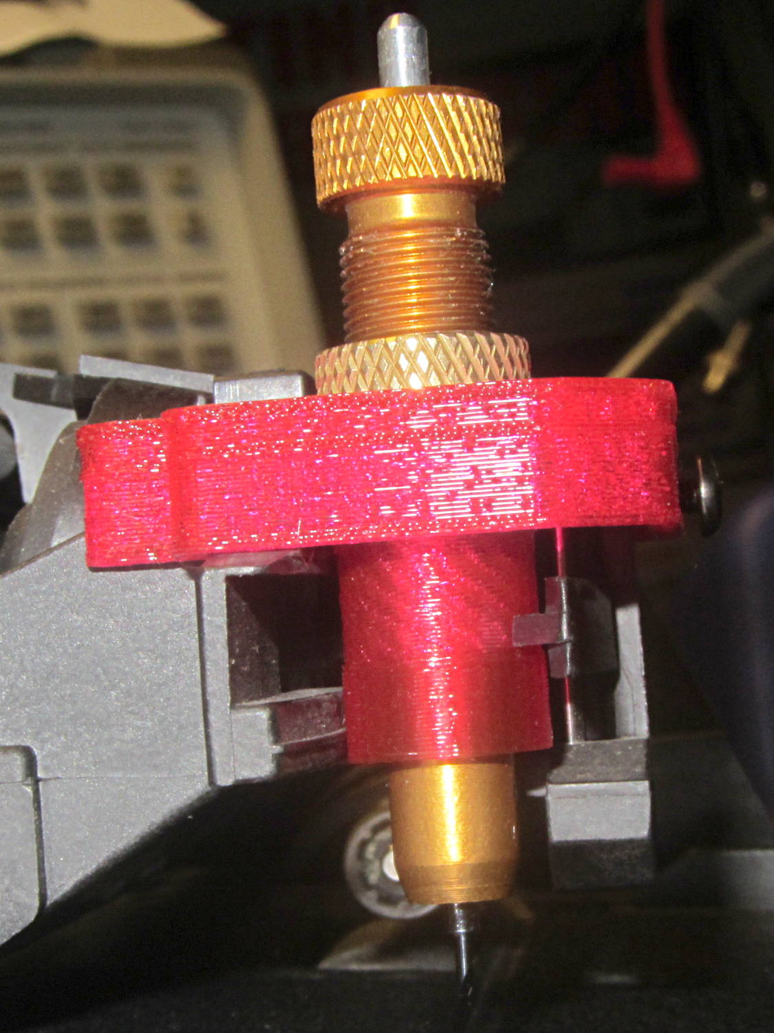
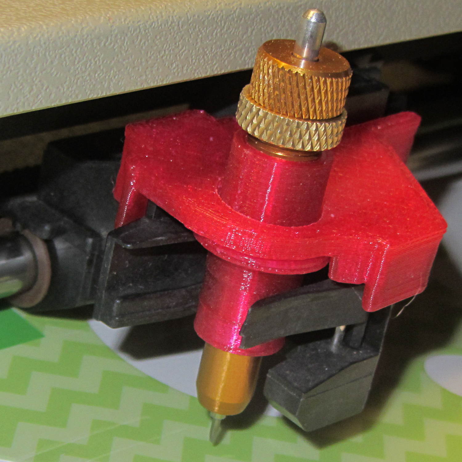
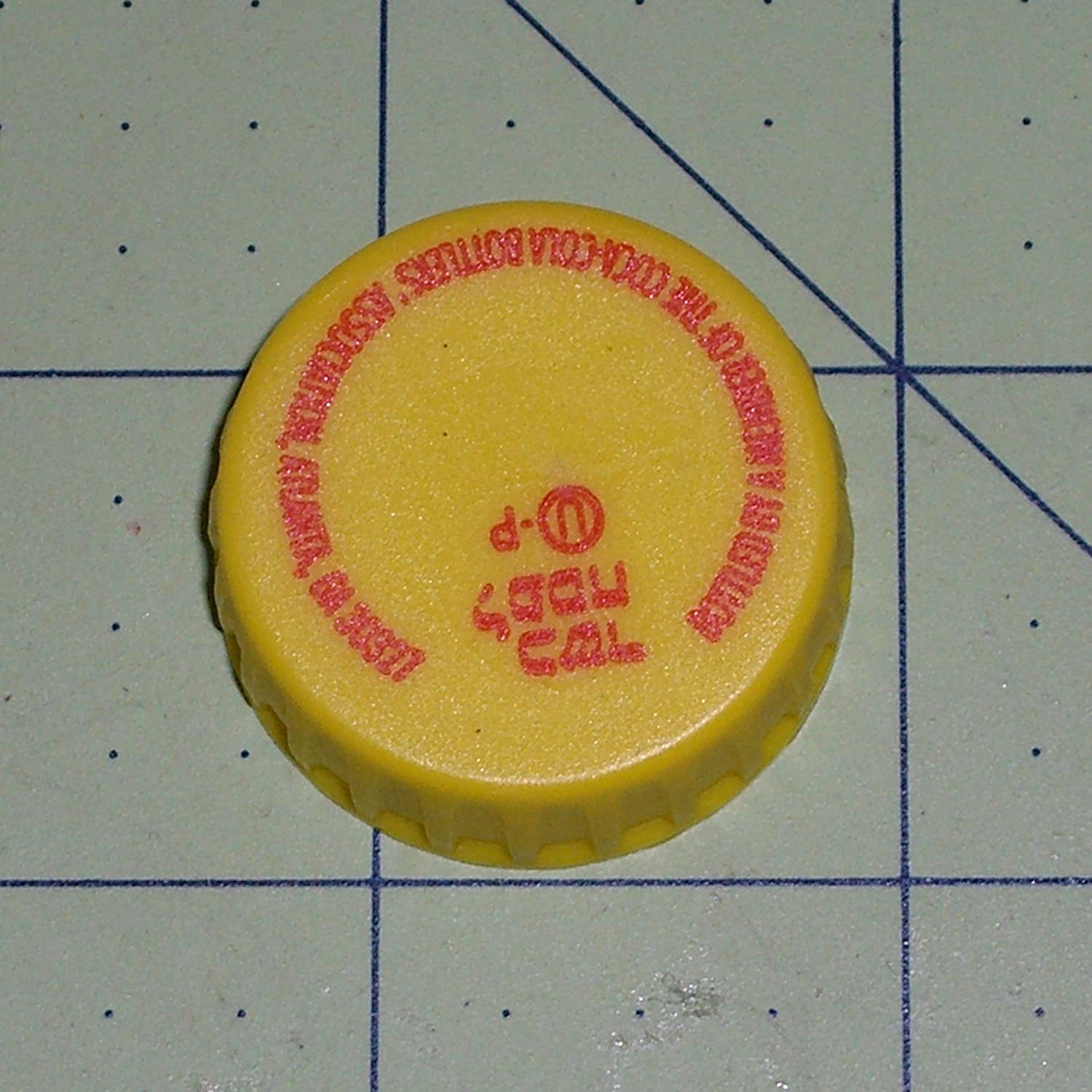
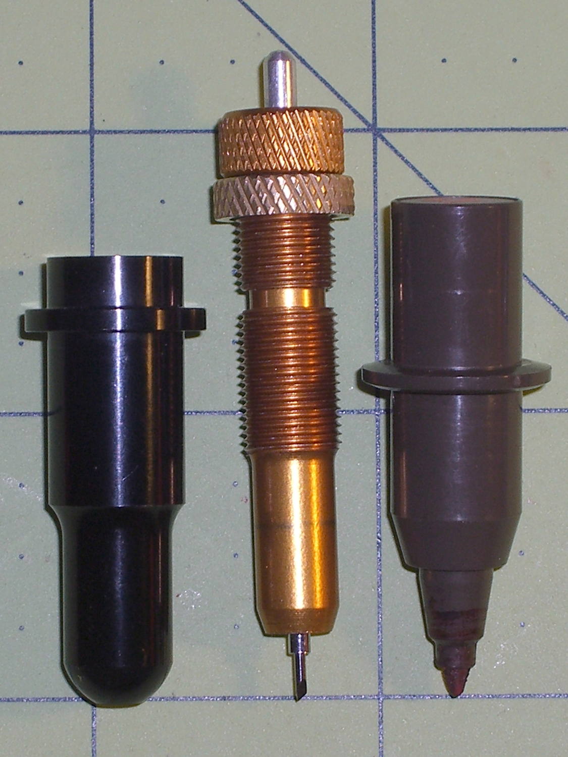
The objective being to wrap a nose around the cutter blade to allow some control over the cut depth, I lengthened the cylinder around the cutter body and modeled a discrete glue-on cap:

Which, with an additional 80 g of ballast, worked fine in the double-thick vinyl:

The pen-lift spring can just barely manage to heave that load off the vinyl, but it’s obviously running at the limit of its ability and this can’t possibly be a Good Thing for the mechanism in the long run.
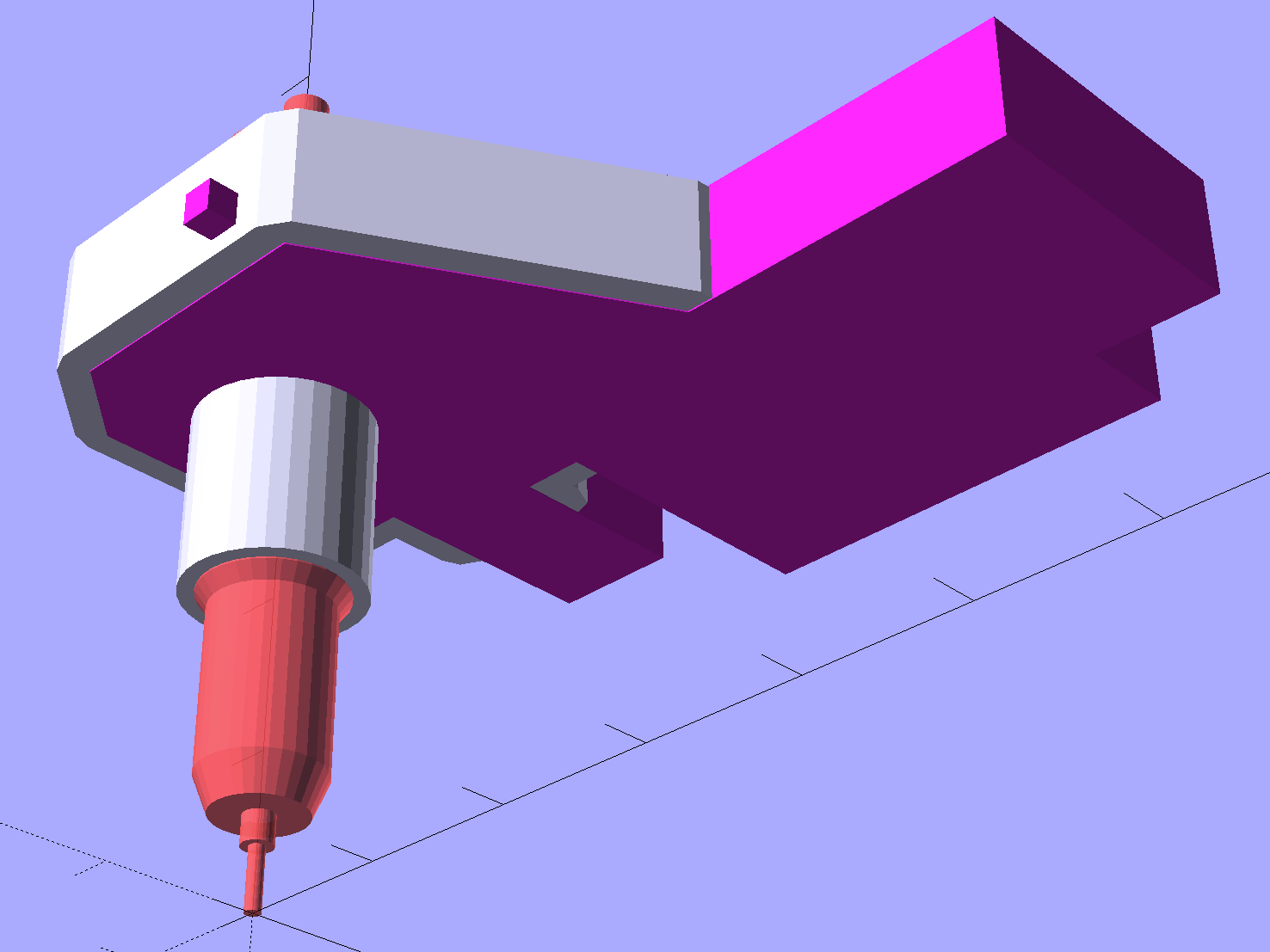
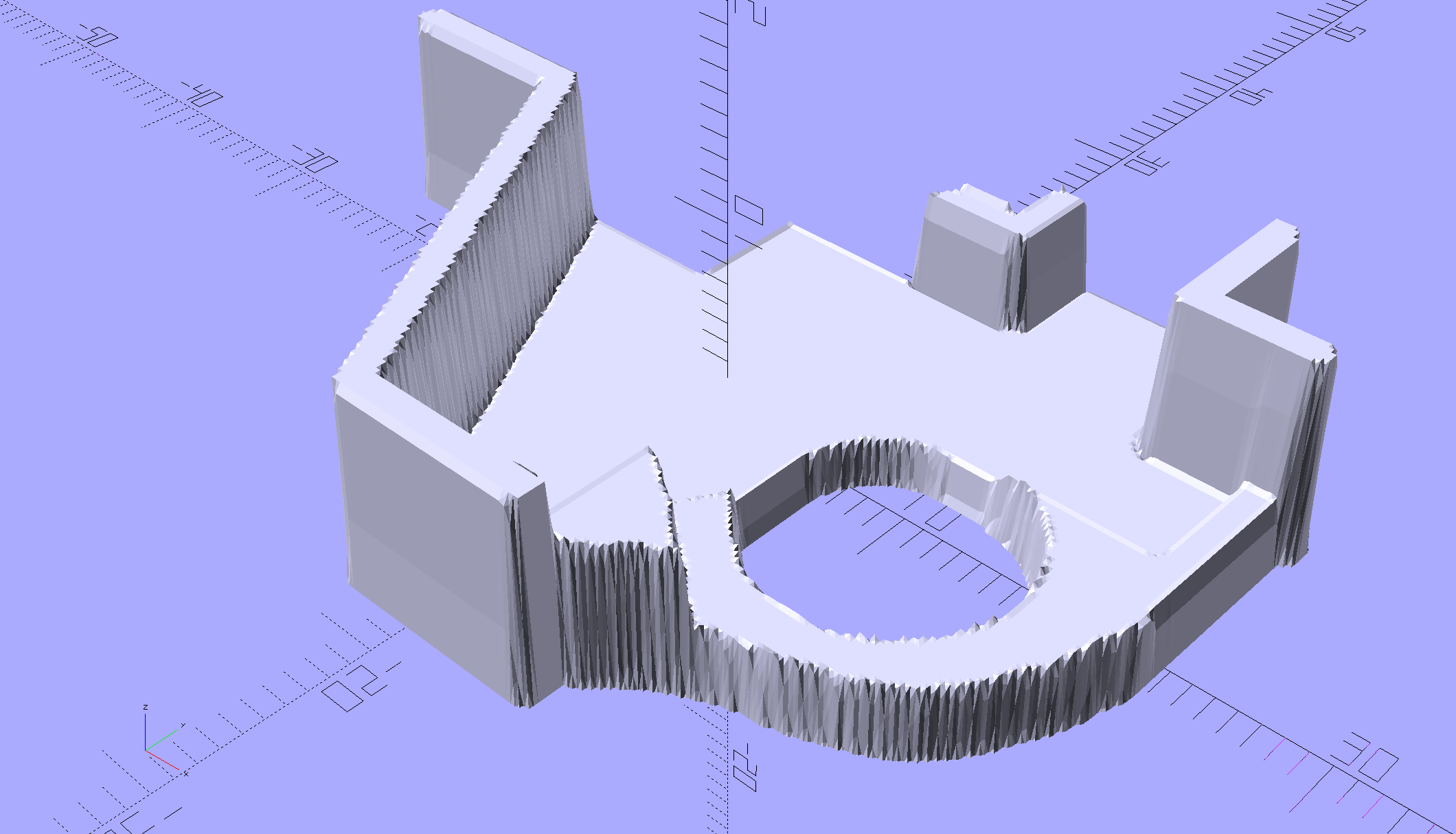
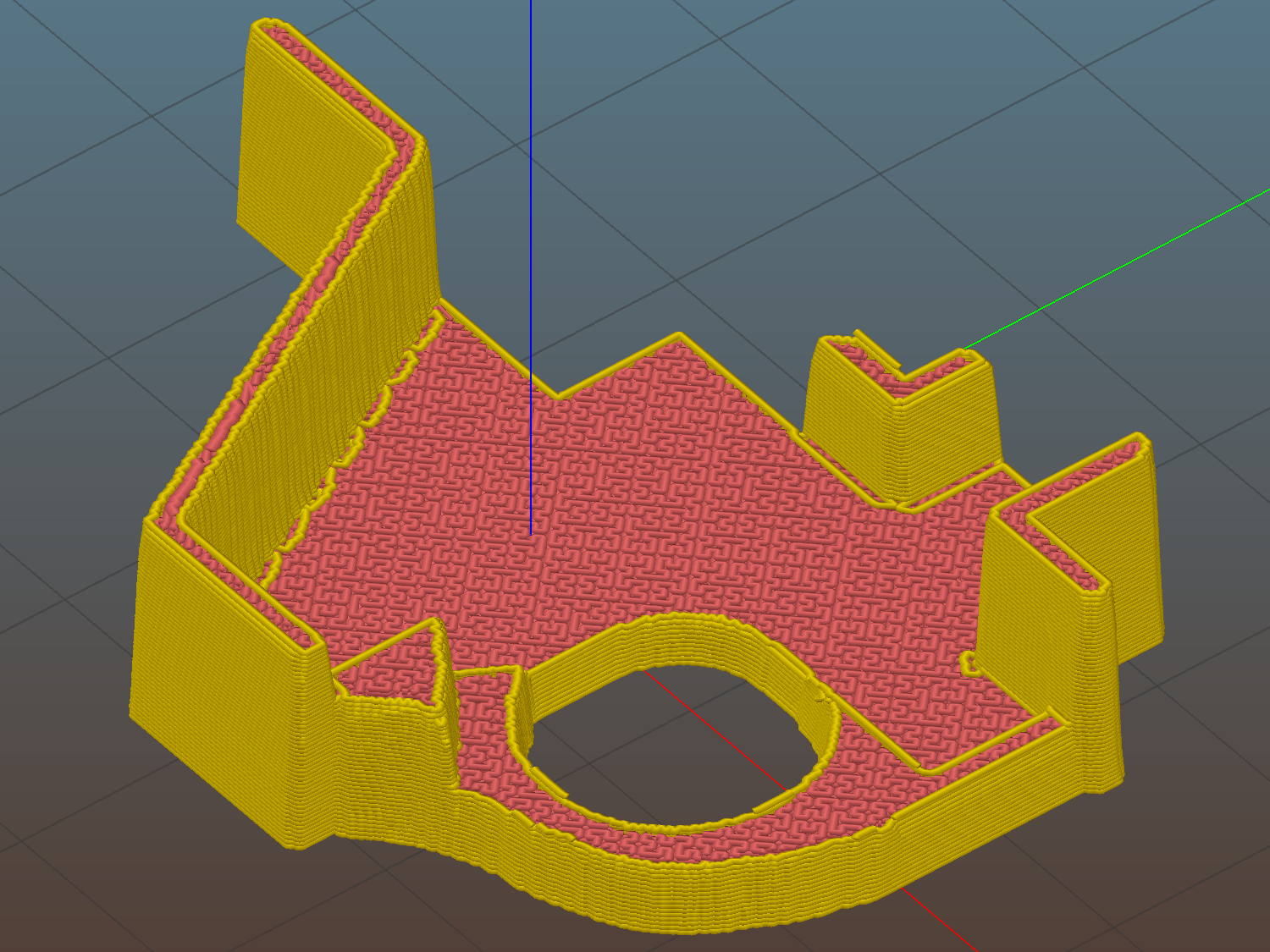
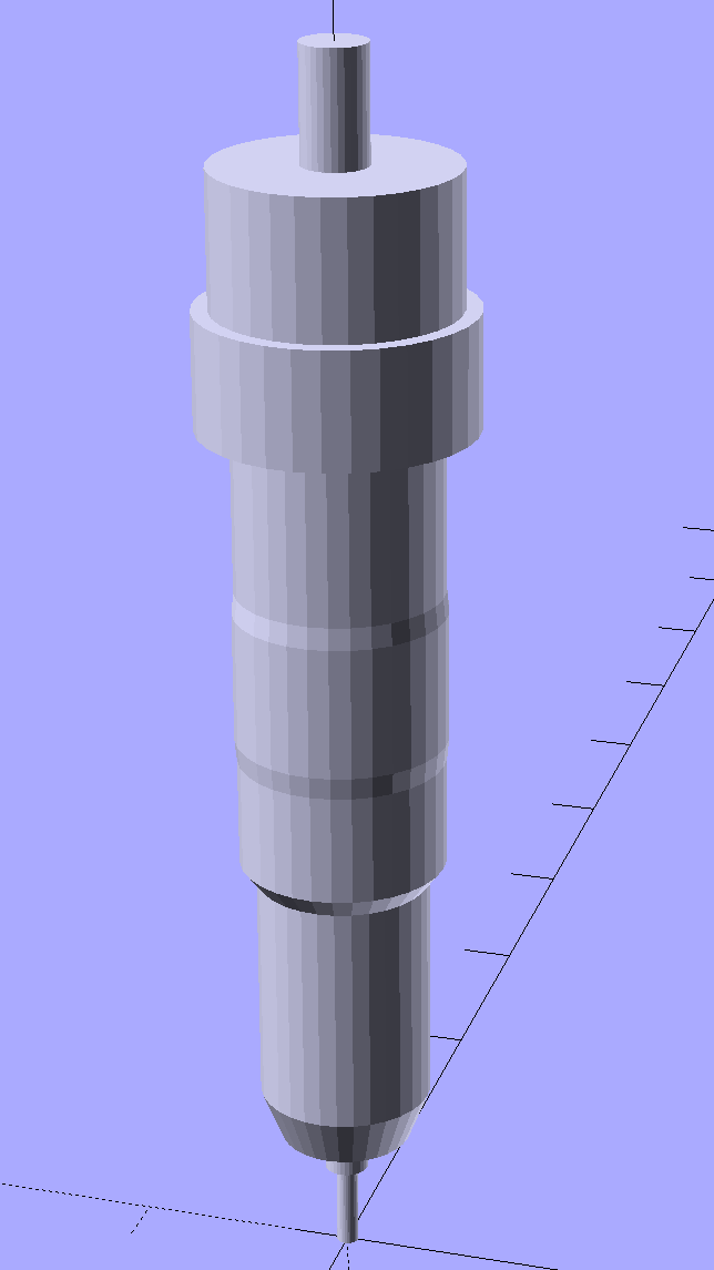
After a bit more fiddling around, I noticed that the stabilizer wasn’t sitting flat on the pen holder and that there really wasn’t any good reason to have a separate cap, so I did one more revision:

The cutaway view shows the knife model now has tapered transition from the body to the grossly enlarged blade, so the model will build without supports inside the cylinder.
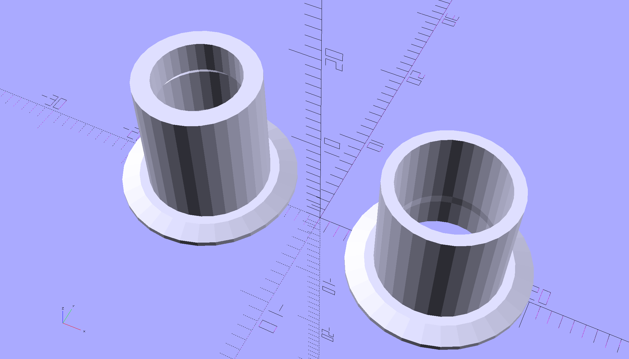
A little cutout on one wall lets the plate sit flat on the pen holder and a barely visible recess in the cylinder gives the carousel pen-capping actuator a bit more clearance:

It works about as well as the version shown above, minus the tedious gluing, so I’ll call it a success… even though it’s obviously not going to get much use. I don’t see any way to apply enough downforce to make the cutter work; the mechanical changes just aren’t worthwhile.
The OpenSCAD source code, which includes some tweaks and outright kludges since the first version, builds adapters for Sakura pens (which work just fine) as well as this knife stabilizer:
// HP 7475A plotter pen adapters
// Ed Nisley KE4ZNU April 2015

Layout = "BuildStabilizer";
							// ShowBody BuildBody BodyPoly
							// ShowPen ShowPenAdapter BuildPenAdapter Plug Pen PenPoly
							// ShowKnife BuildKnife KnifeAdapter Knife
							// ShowStabilizer Stabilizer BuildStabilizer

//- Extrusion parameters must match reality!

ThreadThick = 0.25;
ThreadWidth = 0.40;

HoleWindage = 0.2;

Protrusion = 0.1;			// make holes end cleanly

inch = 25.4;

function IntegerMultiple(Size,Unit) = Unit * ceil(Size / Unit);

//----------------------
// Dimensions
// Z=0 at pen tip!

NumSides = 8*4;						// number of sides on each "cylinder"

RADIUS = 0;							// subscript for radius values
HEIGHT = 1;							//   ... height above Z=0

//-- Original HP plotter pen, which now serves as a body for the actual pen

BodyOutline = [						// X values = (measured diameter)/2, Y as distance from tip
	[0.0,0.0],						//  0 fiber pen tip
//	[2.0/2,1.4],					//  1 ... taper (not buildable)
	[1.0/2,0.005],					//  1 ... faked point to remove taper
	[2.0/2,0.0],[2.0/2,2.7],		//  2 ... cylinder
	[3.7/2,2.7],[3.7/2,4.45],		//  4 tip surround
	[4.8/2,5.2],					//  6 chamfer
	[6.5/2,11.4],					//  7 rubber seal face
	[8.9/2,11.4],					//  8 cap seat
	[11.2/2,15.9],					//  9 taper to body
	[11.5/2,28.0],					// 10 lower body
	[13.2/2,28.0],[16.6/2,28.5],	// 11 lower flange = 0.5
	[16.6/2,29.5],[13.2/2,30.0],	// 13 flange rim = 1.0
	[11.5/2,30.0],					// 15 upper flange = 0.5
	[11.5/2,43.25],					// 16 upper body
	[0.0,43.25]						// 17 lid over reservoir
	];

TrimHeight = BodyOutline[9][HEIGHT];		// cut off at top of lower taper
SplitHeight = (BodyOutline[11][HEIGHT] + BodyOutline[14][HEIGHT])/2;	// middle of flange

FlangeOD = 2*BodyOutline[13][RADIUS];
FlangeTop = BodyOutline[15][HEIGHT];

BodyOD = 2*BodyOutline[16][RADIUS];
BodyOAL = BodyOutline[17][HEIGHT];

echo(str("Trim: ",TrimHeight));
echo(str("Split: ",SplitHeight));

BuildSpace = FlangeOD;

//-- Sakura Micron fiber-point pen

ExpRP = 0.15;						// expand critical sections (by radius)

//-- pen locates in holder against end of outer body

PenOutline = [
	[0,0],							//  0 fiber pen tip
	[0.6/2,0.0],[0.6/2,0.9],		//  1  ... cylinder
	[1.5/2,0.9],[1.5/2,5.3],		//  3 tip surround
	[4.7/2,5.8],					//  5 chamfer
	[4.9/2,12.3],					//  6 nose
//	[8.0/2,12.3],[8.0/2,13.1],		//  7 latch ring
//	[8.05/2,13.1],[8.25/2,30.5],	//  9 actual inner body
	[8.4/2 + ExpRP,12.3],[8.4/2 + ExpRP,30.5],	//  7 inner body - clear latch ring
	[9.5/2 + ExpRP,30.5],			//  9 outer body - location surface!
	[9.8/2 + ExpRP,50.0],			// 10 outer body - length > Body
	[7.5/2,50.0],					// 11 arbitrary length
	[7.5/2,49.0],					// 12 end of reservoir
	[0,49.0]						// 13 fake reservoir
	];

PenNose = PenOutline[6];
PenLatch = PenOutline[7];

PenOAL = PenOutline[11][HEIGHT];

//-- Plug for end of cut-off pen body
//   you need two plugs...

PlugOutline = [
	[0,0],							// 0 center of lid
	[9.5/2,0.0],[9.5/2,1.0],		// 1 lid rim <= body OD
	[7.9/2,1.0],					// 3 against end of pen
	[7.6/2,6.0],					// 4 taper inside pen body
	[5.3/2,6.0],					// 5 against ink reservoir
	[4.0/2,1.0],					// 6 taper to lid
	[0.0,1.0]						// 7 flat end of taper
	];

PlugOAL = PlugOutline[5][HEIGHT];

//   cap locates against end of inner body at latch ring
//-- cap origin is below surface to let pen tip be at Z=0

CapGap = 1.0;						// gap to adapter body when attached
CapGripHeight = 2.0;				// thickness of cap grip flange
CapTipClearance = 1.0;				// clearance under fiber tip

CapOffset = -(CapGripHeight + CapTipClearance);	// align inside at pen tip Z=0

CapOutline = [
	[0,CapOffset],									// 0 base
	[FlangeOD/2,CapOffset],							// 1 finger grip flange
	[FlangeOD/2,CapOffset + CapGripHeight],			// 2  ... top
	[BodyOD/2,CapOffset + CapGripHeight],			// 3 shaft
	[BodyOD/2,TrimHeight - CapGap],					// 4  ... top with clearance
	[PenLatch[RADIUS],TrimHeight - CapGap],			// 5 around pen latch ring
	[PenLatch[RADIUS],PenNose[HEIGHT]],				// 6  ... location surface!
	[PenNose[RADIUS] + ExpRP,PenNose[HEIGHT]],		// 7 snug around  nose
	[PenNose[RADIUS] + ExpRP,-CapTipClearance],		// 8 clearance around tip
	[0,-CapTipClearance],							// 9  ... bottom
	];

//-- Roland drag knife bearing assembly

ExpRK = 0.30;						// expand critical sections (by radius)
AdjLen = 2.0;						// allowance for adjustment travel

//- Knife tweaked for pen adapter
/*
KnifeOutline = [
	[0,0],							//  0 blade point (actually 0.25 mm offset)
	[1.0/2,0.0],					//  1  ... blunt end
	[1.0/2,4.0],					//  2  ... cylinder
	[2.0/2,4.0],					//  3 blade shank
	[2.0/2,5.9],					//  4  .. at bearing
	[6.0/2,5.9],					//  5 holder - shell

	[7.3/2 + ExpRK,8.3],			//  6 holder - taper to body
	[7.3/2 + ExpRK,21.0 - AdjLen],	//  7 holder body

	[8.8/2 + ExpRK,22.0 - AdjLen],	//  8 holder - threads bottom
	[8.8/2 + ExpRK,25.0],[9.0/2 + ExpRK,26.0],		//  9 clear threads to reduce friction
	[9.0/2 + ExpRK,32.0],[8.8/2 + ExpRK,33.0],		// 11  ... end clearance
	[8.8/2 + ExpRK,42.5 - AdjLen],	// 13 holder - threads top = locknut bottom
	[12.5/2,42.5 - AdjLen],			// 14 knurled locknut - adjustment travel
	[12.5/2,45.8],					// 15 knurled locknut - top
	[11.0/2,45.8],					// 16 holder - adjusting knurl
	[11.0/2,52.0],					// 17 holder - top surface
	[3.0/2,52.0],[3.0/2,57.2],		// 18 spring post
	[0.0,57.2]						// 19 end of post
	];
*/

//- Knife tweaked for stabilizer

KnifeOutline = [
	[0,0],							//  0 blade point (actually 0.25 mm offset)
	[3.0/2,0.0],					//  1  ... blunt end
	[3.0/2,4.0],					//  2  ... cylinder
	[3.0/2,4.0],					//  3 blade shank
	[6.0/2,5.9],					//  4  .. at bearing (taper to support nose)
	[6.0/2,5.9],					//  5 holder - shell

	[7.3/2 + ExpRK,8.3],			//  6 holder - taper to clear threads
	[7.3/2 + ExpRK,21.0 - AdjLen],	//  7  ..

	[8.8/2 + ExpRK,22.0 - AdjLen],	//  8 holder - threads bottom
	[8.8/2 + ExpRK,25.0],[9.0/2 + ExpRK,26.0],		//  9 clear threads to reduce friction
	[9.0/2 + ExpRK,32.0],[8.8/2 + ExpRK,33.0],		// 11  ... end clearance

	[8.8/2 + ExpRK,42.5 - AdjLen],	// 13 holder - threads top = locknut bottom
	[12.5/2,42.5 - AdjLen],			// 14 knurled locknut - adjustment travel
	[12.5/2,45.8],					// 15 knurled locknut - top
	[11.0/2,45.8],					// 16 holder - adjusting knurl
	[11.0/2,52.0],					// 17 holder - top surface
	[3.0/2,52.0],[3.0/2,57.2],		// 18 spring post
	[0.0,57.2]						// 19 end of post
	];

ThreadStart = KnifeOutline[8][HEIGHT];
ThreadOD = 2*KnifeOutline[11][RADIUS];

//-- Plotter pen holder stabilizer

HolderPlateThick = 3.0;				// thickness of plate atop holder
RimHeight = 5.0;					// rim around sides of holder
RimThick = 2.0;						// wall thickness

HolderOrigin = [17.0,12.2,0.0];		// center of pen tip relative to polygon coordinates

HolderHeight = 30.0;				// top of holder to platen in pen-down position
HolderTopThick = 1.7;				// top of holder to top of pen flange

HolderNoseLength = 4.0;				// length of nose taper
HolderKnifeOffset = -3.0;			// additional downward adjustment range

LockScrewInset = 3.0;				// from right edge of holder plate
LockScrewOD = 2.0;					// tap for 2.5 mm screw

UncapperHeight = -17.0;				// uncapping actuator arm from top of pen holder
UncapperOD = 11.0;					//  ... max OD that clears uncapper

// Beware: update hardcoded subscripts in Stabilizer() when adding / deleting point entries

HolderPlate = [
	[8.6,18.2],[8.6,23.9],			// 0 lower left corner of pen recess
	[13.9,23.9],[13.9,30.0],		// 2
//	[15.5,30.0],[15.5,25.0],		// 4 omit middle of support beam
//	[20.4,25.0],[20.4,30.0],		// 6
	[22.7,30.0],[22.7,27.5],		// 4
	[35.8,27.5],[35.8,20.7],		// 6 spring box corner
	[43.0,20.7],					// 8
	[31.5,0.0],						// 9
//	[24.5,0.0],[24.5,8.0],			// 10 omit pocket above pen clamp
//	[22.5,10.0],[22.5,16.5],		// 12
//	[20.5,18.2]						// 14
	[13.6,0.0],						// 10
	[8.6,5.0]						// 11
	];

BeamWidth = HolderPlate[4][0] - HolderPlate[2][0];		// rear support beam

TabWidth = HolderPlate[1][1] - HolderPlate[0][1];		// tab extending left beyond pen recess
TabClear = 3.0;											// maximum rim height over tab

HolderCylinderOutline = [
	[0,0],											//  0 center of nose
	[6.0/2,0.0],									//  1 flat nose surface OD
	[BodyOD/2,HolderNoseLength],			//  2 taper to cylinder OD
	[BodyOD/2,HolderHeight],				//  3 cylinder to top of holder plate
	[0,HolderHeight]								//  4 flat top
	];

//----------------------
// Useful routines

module PolyCyl(Dia,Height,ForceSides=0) {			// based on nophead's polyholes

  Sides = (ForceSides != 0) ? ForceSides : (ceil(Dia) + 2);

  FixDia = Dia / cos(180/Sides);

  cylinder(r=(FixDia + HoleWindage)/2,
           h=Height,
	   $fn=Sides);
}

//- Locating pin hole with glue recess
//  Default length is two pin diameters on each side of the split

PinOD = 1.75;
PinOC = BodyOD / 2;

module LocatingPin(Dia=PinOD,Len=0.0) {

	PinLen = (Len != 0.0) ? Len : (4*Dia);

	translate([0,0,-ThreadThick])
		PolyCyl((Dia + 2*ThreadWidth),2*ThreadThick,4);

	translate([0,0,-2*ThreadThick])
		PolyCyl((Dia + 1*ThreadWidth),4*ThreadThick,4);

	translate([0,0,-(Len/2 + ThreadThick)])
		PolyCyl(Dia,(Len + 2*ThreadThick),4);

}

module LocatingPins(Length) {
	for (i=[-1,1])
	translate([0,i*PinOC/2,0])
		rotate(180/4)
		LocatingPin(Len=Length);
}

//----------------------
// Basic shapes

//-- HP plotter pen body

module ShowPolygon(pts) {
	polygon(pts);
}

module Body() {
	render(convexity=3)
		rotate_extrude($fn=NumSides)
			polygon(points=BodyOutline);
}

//-- Sakura drawing pen body

module Pen() {
	rotate_extrude($fn=NumSides)
		polygon(points=PenOutline);
}

//-- Plug for top of Sakura pen

module Plug() {
	render(convexity = 2)
		rotate_extrude($fn=NumSides)
			polygon(points=PlugOutline);
}

//-- Cap for tip of Sakura pen

module Cap() {
	render(convexity = 2)
		rotate_extrude($fn=NumSides)
			polygon(points=CapOutline);
}

//-- Sakura pen adapter

module PenAdapter() {

	render(convexity=3)
		difference() {
			Body();
			Pen();
			translate([0,0,TrimHeight/2])
				cube([2*FlangeOD,2*FlangeOD,TrimHeight],center=true);
		}
}

//-- Roland knife body

module Knife() {
	render(convexity=3)
		rotate_extrude($fn=NumSides)
			polygon(points=KnifeOutline);
}

//-- Roland knife adapter

module KnifeAdapter(TrimZ = false) {

Trans = TrimZ ? - TrimHeight : 0;

	render(convexity=5)
		translate([0,0,Trans])
			difference() {
				Body();
				Knife();
				translate([0,0,TrimHeight/2])
					cube([2*FlangeOD,2*FlangeOD,TrimHeight],center=true);
			}
}

//-- nose cap for stabilizer cylinder

module StabilizerNose() {
	render(convexity = 2)
		rotate_extrude($fn=NumSides)
			polygon(points=StabilizerNoseOutline);
}

//-- Roland knife stabilizer atop pen holder
//   the trim blocks have offsets with magic numbers from the HolderPlate outline &c

module Stabilizer(SeeKnife = false) {

Cutout = (Layout == "ShowStabilizer") ? 0 : 1;

	difference() {
		union() {
			translate(-HolderOrigin)													// put center of pen at origin
			translate([0,0,-RimHeight])													// put top of holder at Z=0
				difference() {
						render(convexity=4)
						linear_extrude(height=(HolderPlateThick + RimHeight))			// overall flange around edges
							offset(r=RimThick)
									polygon(points=HolderPlate);

						render(convexity=4)
						translate([0,0,-Protrusion])									// recess for pen holder plate
							linear_extrude(height=(RimHeight + Protrusion))
								polygon(points=HolderPlate);

						translate([HolderPlate[7][0] - Protrusion,HolderPlate[7][1] - Protrusion,-Protrusion])	// trim spring box from top plate
							cube([30,20,(RimHeight + HolderPlateThick + 2*Protrusion)]);

						translate([27.0,HolderPlate[6][1] - Protrusion,-Protrusion])	// trim pivot plate clearance
							cube([30,20,(RimHeight + HolderPlateThick + 2*Protrusion)]);

						translate([HolderPlate[2][0],20,-Protrusion])					// trim left support beam
							cube([BeamWidth,20,(RimHeight + Protrusion)]);

						translate([0,HolderPlate[0][1],-(TabClear + Protrusion)])		// trim tab behind pen recess
							cube([(HolderPlate[0][0] + Protrusion),TabWidth,RimHeight + Protrusion]);

						translate([HolderPlate[9][0] - LockScrewInset,RimThick,RimHeight - HolderTopThick - LockScrewOD/2])												// lock screw on front edge
							rotate([90,0,0])
								rotate(180/4)
									PolyCyl(LockScrewOD,3*RimThick);					// punch out hold-down screw hole
				}

			difference() {
				translate([0,0,-HolderHeight])											// cylinder and nose
					rotate_extrude($fn=NumSides)
						polygon(points=HolderCylinderOutline);
				translate([-HolderOrigin[0],-(BodyOD + Cutout*UncapperOD/2),(UncapperHeight - HolderHeight)])	// uncapper clearance
					cube([2*HolderOrigin[0],BodyOD,HolderHeight]);
			}
		}

		translate([0,0,-HolderHeight + HolderKnifeOffset])
			if (SeeKnife)
#				Knife();
			else
				Knife();

	}
}

//----------------------
// Build it

if (Layout == "Pen")
	Pen();

if (Layout == "Knife")
	Knife();

if (Layout == "Stabilizer")
	Stabilizer();

if (Layout == "ShowBody")
	Body();

if (Layout == "BodyPoly") {
	ShowPolygon(BodyOutline);
	Body();
}

if (Layout == "PenPoly") {
	ShowPolygon(PenOutline);
	Pen();
}

if (Layout == "BuildBody") {
	Spacing = 0.75*BuildSpace;
	difference() {
		union() {
			translate([Spacing,0,-SplitHeight])
				Body();
			rotate([180,0,0])
				translate([-Spacing,0,-SplitHeight])
					Body();
		}
		translate([0,0,-BodyOAL])
			cube(2*BodyOAL,center=true);
		for (i = [-1,1])
			translate([i*Spacing,0,0])
				LocatingPins(5.0);
	}
}

if (Layout == "Plug")
	Plug();

if (Layout == "KnifeAdapter")
	KnifeAdapter();

if (Layout == "ShowPen") {
	color("AntiqueWhite") {
		Pen();
		translate([-1.5*BodyOD,0,0])
			Pen();
	}
	color("Magenta",0.35) {
		translate([0,0,PlugOAL + PenOAL + 3.0])
			rotate([180,0,0])
				Plug();
		PenAdapter();
		Cap();
	}
	color("Magenta") {
		translate([1.5*BodyOD,0,PlugOAL + PenOAL + 3.0])
			rotate([180,0,0])
				Plug();
		translate([1.5*BodyOD,0,0]) {
			PenAdapter();
			Cap();
		}
	}
}

if (Layout == "ShowPenAdapter") {
	color("AntiqueWhite") {
		translate([0.00*BodyOD,0,0])
			Pen();
		translate([-2.75*BodyOD,0,0])
			Pen();
	}

	translate([-1.50*BodyOD,0,0])
		color("SandyBrown")
			Body();

	translate([0.00*BodyOD,0,0])
		color("SandyBrown",0.35)
			PenAdapter();

	translate([3.00*BodyOD,0,0])
		color("SandyBrown")
			PenAdapter();

	translate([1.50*BodyOD,0,0])
		difference() {
			color("SandyBrown")
				PenAdapter();
			translate([-BodyOD,-2*BodyOD,0])
				cube([2*BodyOD,2*BodyOD,PenOAL]);
		}

}

if (Layout == "ShowKnife") {

	color("Goldenrod") {
		Knife();
		translate([-1.5*BodyOD,0,0])
			Knife();
	}
	color("Magenta",0.35)
		KnifeAdapter();
	color("Magenta") {
		translate([1.5*BodyOD,0,0])
			KnifeAdapter();
	}

}

if (Layout == "BuildPenAdapter") {

	if (false) {
		for (j = [-1,1])
			translate([j*BuildSpace/2,-0.7*BuildSpace,0])
			Plug();

		translate([0,0,-CapOffset])
			Cap();
	}
	else {
		Plug();
	}

	difference() {
		union() {
			translate([1.20*BuildSpace,0,-SplitHeight])
				PenAdapter();
			rotate([180,0,0])
				translate([-1.20*BuildSpace,0,-SplitHeight])
					PenAdapter();
		}
		translate([0,0,-BodyOAL])
			cube(2*BodyOAL,center=true);
	}

}

if (Layout == "BuildKnife") {

	difference() {
		union() {
			translate([0.7*BuildSpace,0,-SplitHeight])
				KnifeAdapter(false);
			rotate([180,0,0])
				translate([-0.7*BuildSpace,0,-SplitHeight])
					KnifeAdapter(false);
		}
		translate([0,0,-BodyOAL])
			cube(2*BodyOAL,center=true);
	}

}

if (Layout == "BuildStabilizer") {

	translate([0,0,HolderPlateThick])
		rotate([0,180,0])
			Stabilizer(false);
}

if (Layout == "ShowStabilizer") {

	translate([BuildSpace/2,0,HolderHeight])
			Stabilizer(true);
	translate([-BuildSpace/2,0,HolderKnifeOffset])
		Knife();
}