Ed Nisley's Blog: Shop notes, electronics, firmware, machinery, 3D printing, laser cuttery, and curiosities. Contents: 100% human thinking, 0% AI slop.
Having experimentally determined that tempering molten chocolate is not optional (i.e., chocolate doesn’t behave just like butter), I tried a cheat discussed in the comments following that helpful post. Basically, because all retail chocolate is already tempered, you can get good results by carefully heating it to the proper temperature, then pouring it into the molds… the proper crystals remain in their places, the cooled chocolate has good snap, and you avoid a huge amount of fuffing and fawing.
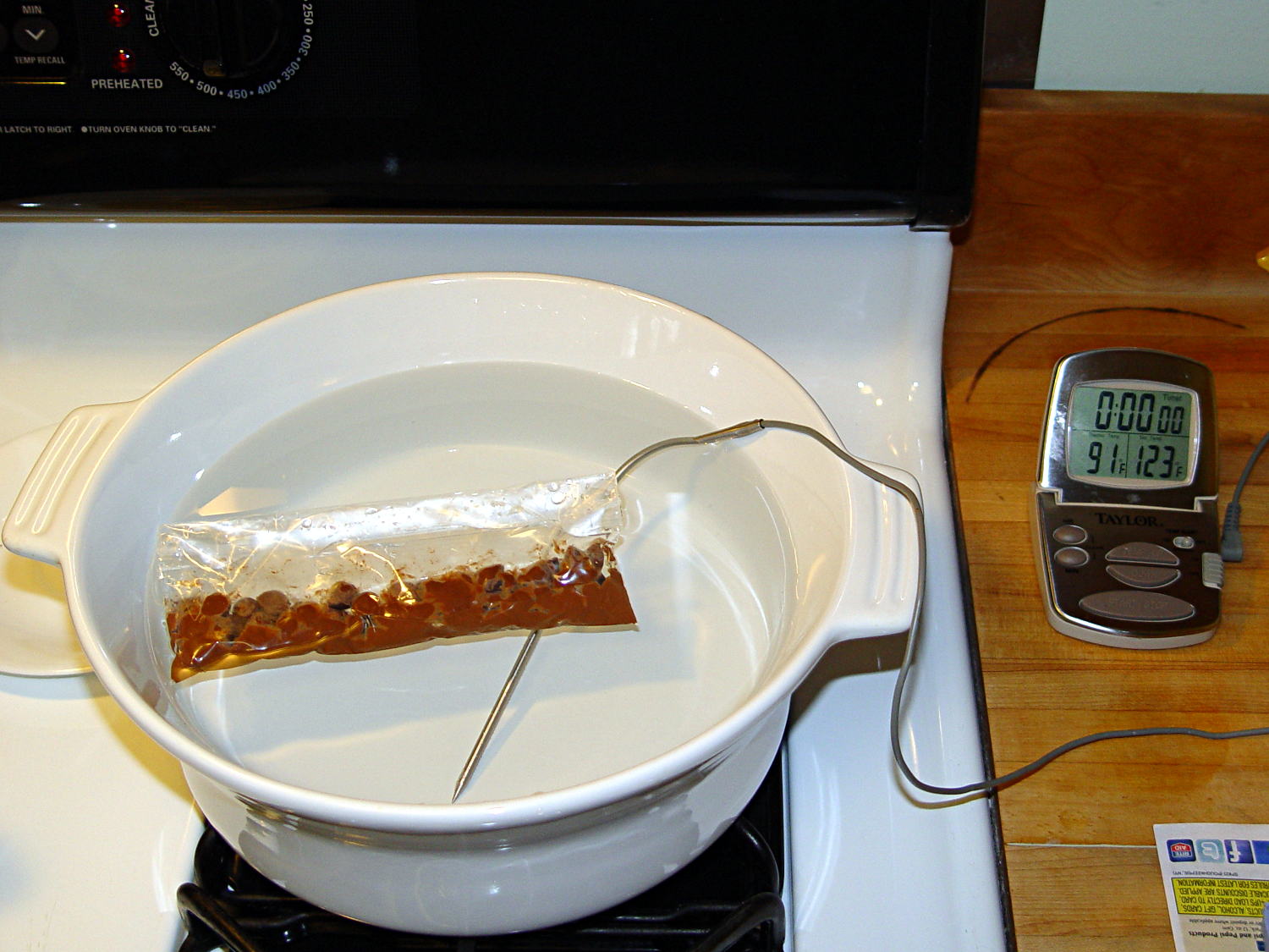
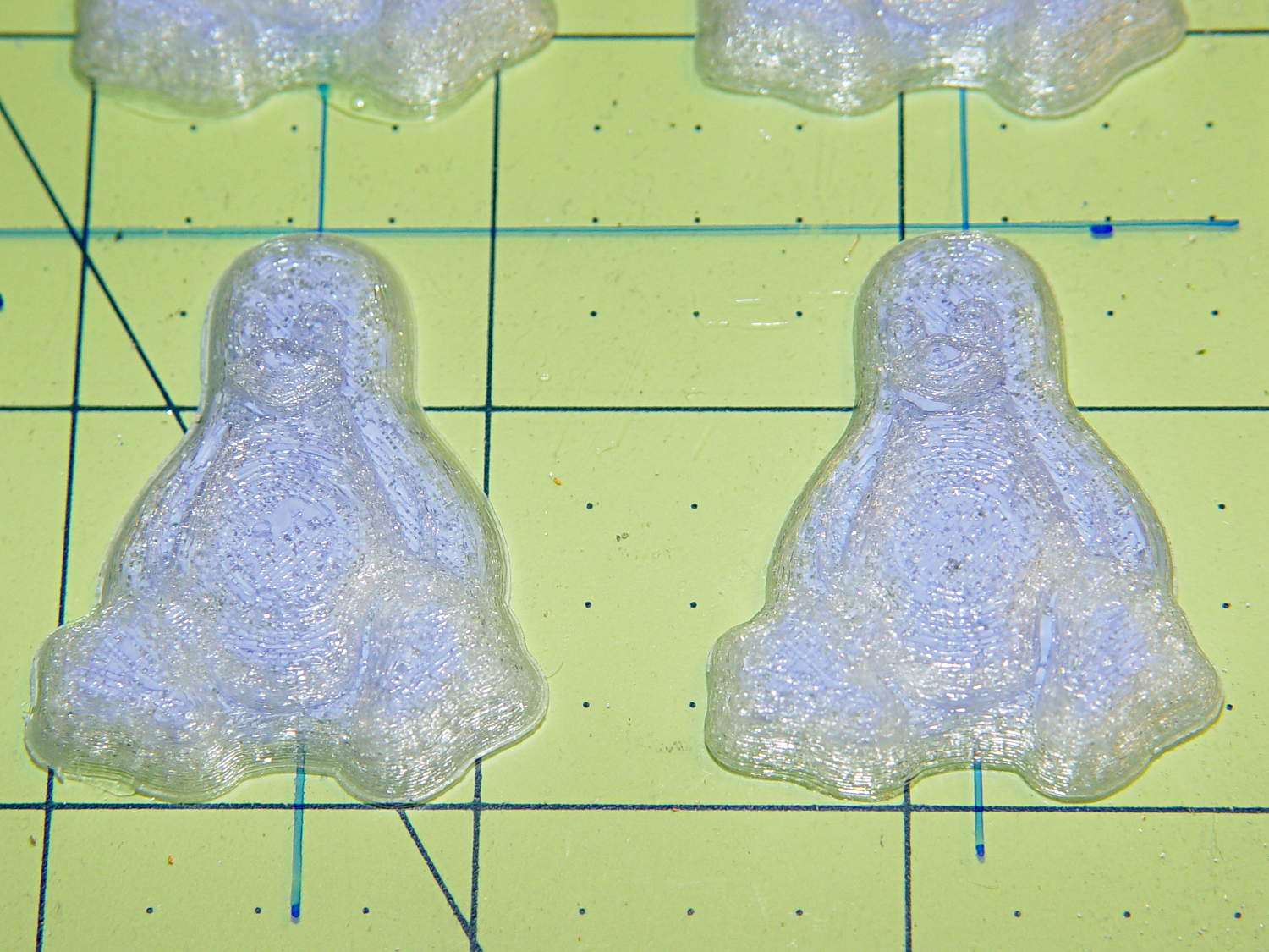
Not having a sous vide setup, but also not working with giant chocolate blocks, I simply filled a big ceramic pot with tepid water:
Chocolate tempering – water bath
Note that the gas burner under the pot is off: the pot’s on the stove because it fit nicely next to the countertop.
A small metal pot sits out of sight on the burner to the left. Goosed with low heat as needed, that pot provided warm water: I moved a cup of tepid water to the metal pot, moved a cup of slightly warmer water back to the ceramic pot, and repeated as needed. As it turned out, the big pot held its heat quite well and the whole process went swimmingly, with the water temperature at 90±1°F, tops.
The Official Tempering Numbers seem to be:
Dark chocolate: 88 – 90°F
Milk chocolate: 86 – 88°F
I suppose I should have used slightly cooler water for the milk chocolate shown in the picture, but it came out Just Fine.
I used Nestlé Toll House Chocolate Morsels for lack of anything better. As nearly as I can tell, cheaper chocolate isn’t really chocolate and fancier chocolate seemed like a Bad Idea until I’ve made a few more mistakes. One bag each of Milk, Dark, and Semi-Sweet sufficed for my simple needs.
The ziplock baggie holds 50 g of chocolate chunks / morsels / whatever, which turned out to be exactly the right amount to fill 16 Tux mold cavities with a 5 mm maximum depth, plus a little bit for the inevitable mess. Sometimes, I just get lucky…
Put chocolate chunks into bag, squeeze out as much air as possible, seal, drop in the pot. Wait a few minutes until it’s not quite completely melted, remove, dry the bag, squeeze out the rest of the air, then knead until it’s all mooshy.
Then cut off one corner of the bag, squeeze chocolate into mold cavities, and flatten the back. I started by easing it into the beak and eyes, filling the tummy, then piling enough to cover everything else. This worked surprisingly well, although the ziplock can unlock if you squeeze hard enough; cut the corner a little bit larger than seems necessary.
Memo to Self: tape the ziplock part of the bag closed to prevent bloopers.
I used a plastic scraper (well, an unused credit card, if you must know) to moosh the chocolate into the cavity and level the back. There doesn’t seem to be much to choose between doing one cavity at a time or a whole row in one pass, although filling more than one row lets the first lump get too cool.
I worried about the chocolate in the bag getting too cool, until I realized that my fingers are hotter than the tempering bath, so, if anything, it would get too hot.
The result came out surprisingly tidy:
Tux Gradient 4×4 – milk chocolate in mold
The silicone block sits atop an aluminum pizza pan, which I transported to the basement for cooling while filling and melting the next bag; the chocolate popped right out of the cavities at about 70°F.
The result looked pretty good to me:
Tux Gradient 4×4 – milk chocolate detail
The detail come out fine and if anybody kvetches about a few bubbles, they don’t get any more.
From left to right, Tux in milk, semi-sweet, and dark chocolate:
Tux Gradient – milk semi-sweet dark lineup
The semi-sweet Tuxes began to bloom almost instantly. I had heated the silicone mold to about 90°F in an attempt to keep the chocolate melty enough to fill 16 cavities before leveling them all at once, but I think it was too hot on the bottom; the four center pieces bloomed right out of the mold and a few others bloomed shortly thereafter.
The bloom highlights the mold detail, though:
Tux Gradient – semi-sweet chocolate bloom
I quickly destroyed all the evidence…
Each Tux weighs 2.5 to 3 g. You do the calorie count yourself, OK?
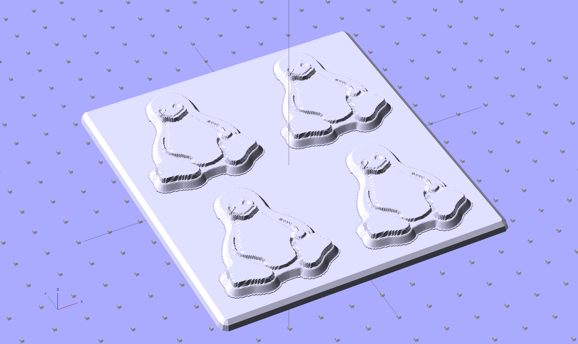
Although directly printing the 2×2 molds worked reasonably well, that does not scale to larger arrays, because OpenSCAD doesn’t handle the profusion of vertices with any grace. Duplicating the STL file created from the height map image, however, isn’t a problem:
Tux-Gradient – Slic3r layout
I actually did it in two passes: 4 molds to be sure they’d come out right, then another dozen. Figure a bit under two hours for the lot of them, no matter how you, ah, slice it.
A grid drawn directly on 1/16 inch = 1.5 mm acrylic sheet guided the layout:
Tux Gradient 4×4 – mold as-cast
I anointed the back of each mold positive with PVC pipe cement, the version with tetrahydrofuran to attack the PLA and acetone/MEK to attack the acrylic, lined it up, and pressed it in place. The positives have recesses for alignment pins, but even I think that’s overkill in this application.
Memo to Self: Flip the acrylic over before gluing, so the guide lines wipe neatly off the bottom.
Tape a cardboard frame around the acrylic, mix & pour the silicone, put it on the floor to ensure it’s level (unlike our kitchen table), wait overnight for the cure, then peel positive and negative apart:
Tux Gradient 4×4 – mold separated
As before, the top surface of the positives isn’t watertight, so the silicone flowed through into the molds. This isn’t a simple extruder calibration issue, because the thinwall boxes are spot on, all the exterior dimensions are accurate, and everything else seems OK. What’s not OK is that threads on the top and (now that I look at it) bottom surfaces aren’t properly joining.
A closeup of the positive shows silicone between the threads and under the surface:
Tux Gradient 4×4 – postive detail
But the negative silicone looks just fine, in the usual hand-knitted way of all 3D printed parts:
Tux Gradient 4×4 – negative detail
Definitely fewer bubbles than before, although the flange between the flippers (wings? whatever) and the body isn’t as clean as it could be. Doing better may require pulling a vacuum on the silicone, which would mean the positives really must be air-tight solids.
Anyhow, the acrylic base produced a wonderfully flat surface that should make it a lot easier to run a scraper across the chocolate to remove the excess. Not that excess chocolate is ever a problem, but it’s the principle of the thing.
This is the simple height-map Tux image I’d been using for the chocolate molds:
Tux_Hi_Profile
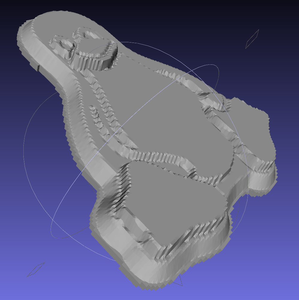
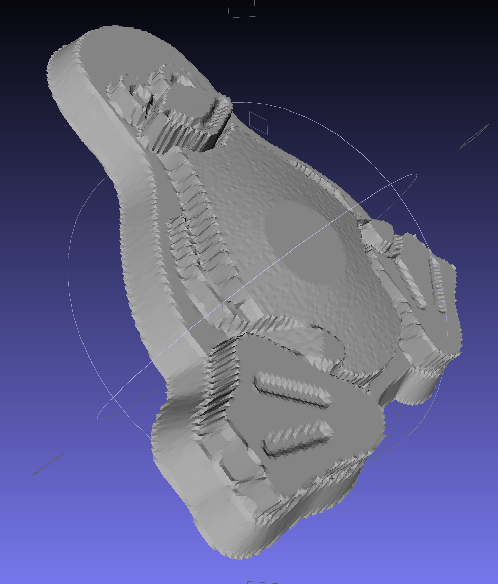
But the poor critter looks a bit flattened:
Tux_Hi_Profile – solid model
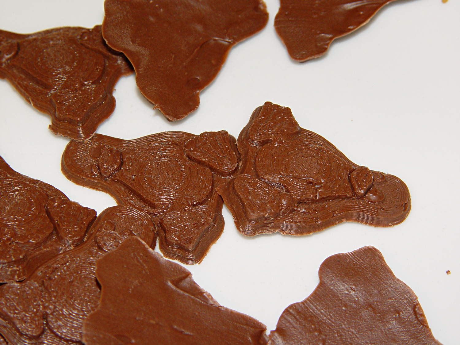
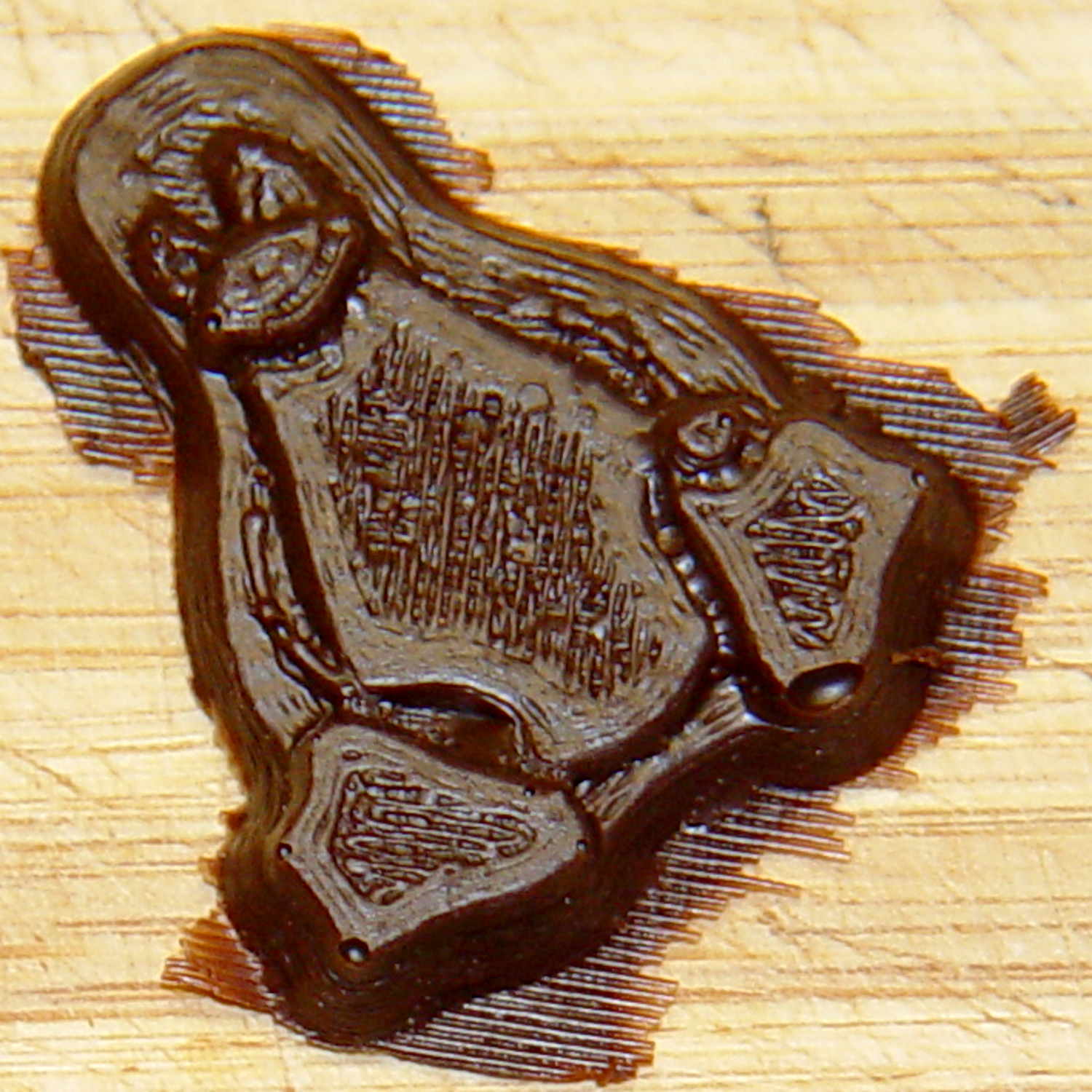
The final result is tastier, but gives off a roadkill vibe:
Tux chocolates – detail
After a few tweaks to the image, now he has a radial gradient on his tummy, his right flipper extends forward, his feet have webs, and his smile looks radiant. The gray levels now extend over a larger range with a bit more separation, with the intent that he’ll now be 5 mm thick:
Recumbent Riders – North Grand Avenue Crossing – 2014-04-05
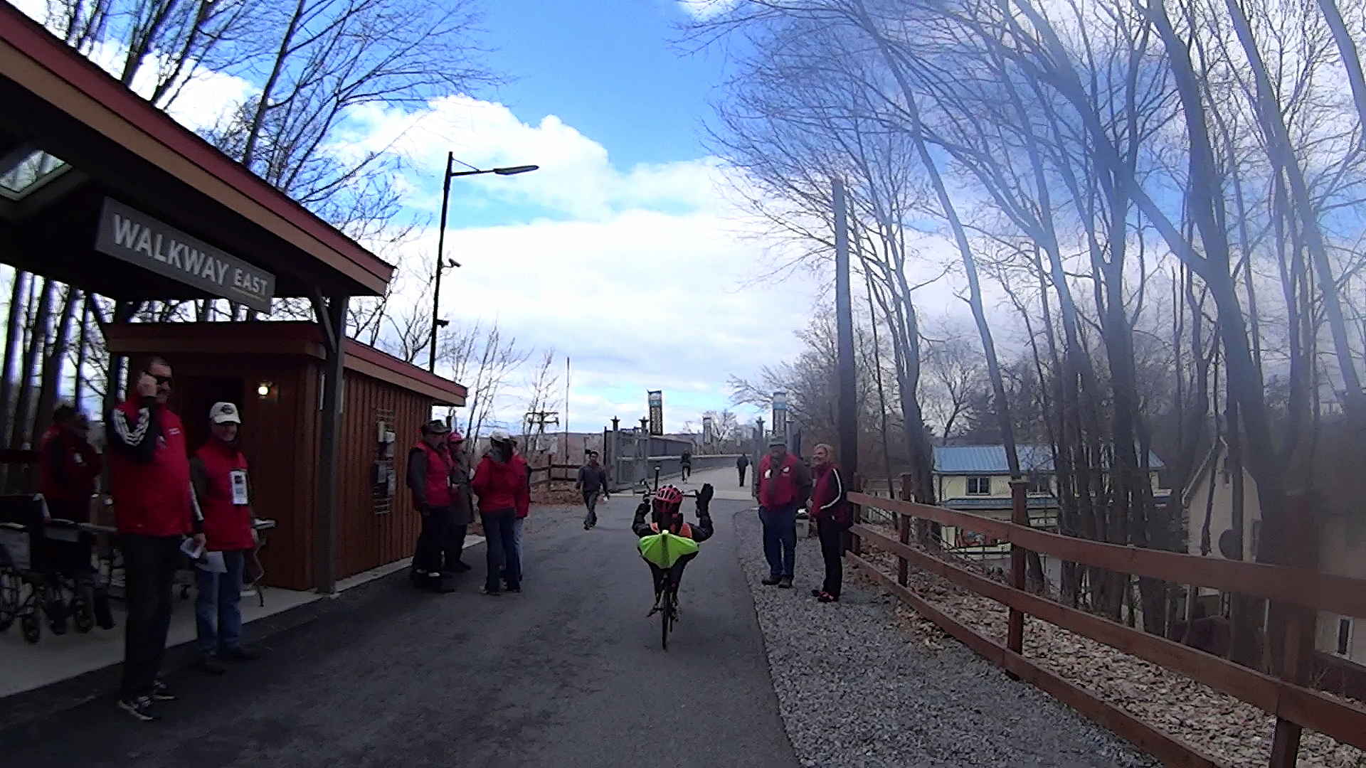
A highracer gingerly navigates the low-speed gauntlet to the Walkway Over the Hudson:
Recumbent Riders – Walkway Over the Hudson Entrance – 2014-04-05
The pix come from the Sony HDR-AS30V helmet camera video, set to 1920×1080 / 120° @ 60 frame/s. They’ve had a bit of refocusing and color adjustment, but nothing can dramatically improve them. The video looks better only because eyes aren’t as fussy with moving images. I’m not red-hot pleased with the resolution & compression, but the camera is what it is.
The lens carried a smear on the upper-right quadrant that shows the sensitivity of the optical path.
Memo to Self: Clean the lens and keep fingers off!
That’s harder than it may seem. The Start button is on the back of the body, recessed far enough into the skeleton frame to require an index finger rather than a thumb, and it’s remarkably easy to touch the bulging fisheye lens with your (well, my) thumb; a touch is all it takes to create a nice smear.
I started and ended at home, rather than at the Hopewell Junction end, but you get the general idea:
As I recall, a few weeks after I bought this packing tape dispenser, I dropped it with the nut downward, whereupon all six of the little tabs that were supposed to hold the tape roll in place broke off, allowing the roll to walk off the holder. Having put up with that for far too long (I don’t do a lot of shipping these days), I finally drilled and tapped three 4-40 holes and ran a trio of setscrews against the inside of the roll core:
Packing tape dispenser – improved spool holder
The holes are angled so that the setscrews bite into the core just enough to prevent it from walking away, but I can still pull the roll off when it’s empty.
A rough estimate of the volume and measurement thereof:
Assume 1 cm slab thickness for mold cavities 4 or 5 mm deep
Measure size of base plate in cm (given by OpenSCAD script in mm)
Compute slab volume in cubic cm = millliliters (ignoring mold cavity volumes)
Divide by 2 to find volume of each silicone component
Mark that volume on the side of two sacrificial containers
Pour silicone components into those containers
Pour one into the other, mix twice as long as you think you should
Scrupulously avoid cross-contaminating the original containers!
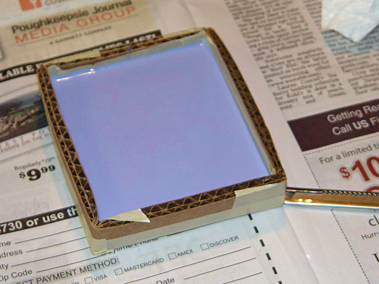
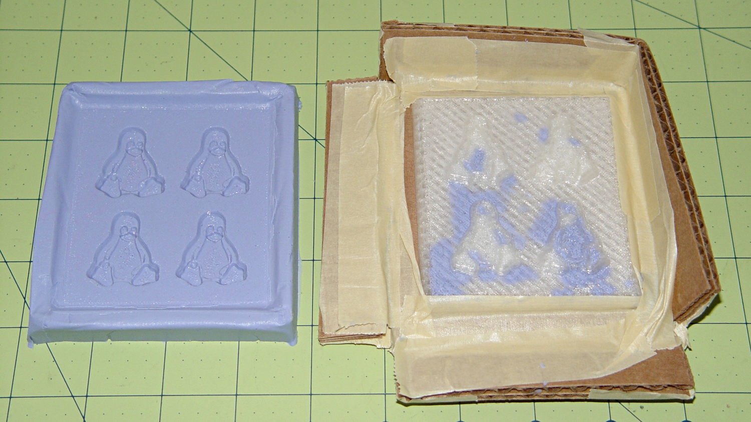
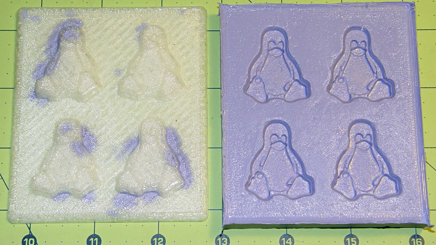
Fast-forward overnight, cut the tape, and peel the silicone negative off the positive:
Tux 2×2 mold – opened
The top surface of the 3D printed positive wasn’t completely water silicone-tight, so the silicone leaked through the top and filled part of the interior. No harm done, but I wasn’t expecting that. The interior of the silicone negative came out pretty well, although you can see some small bubble cavities that may be due to air leaking out through the top of the positive:
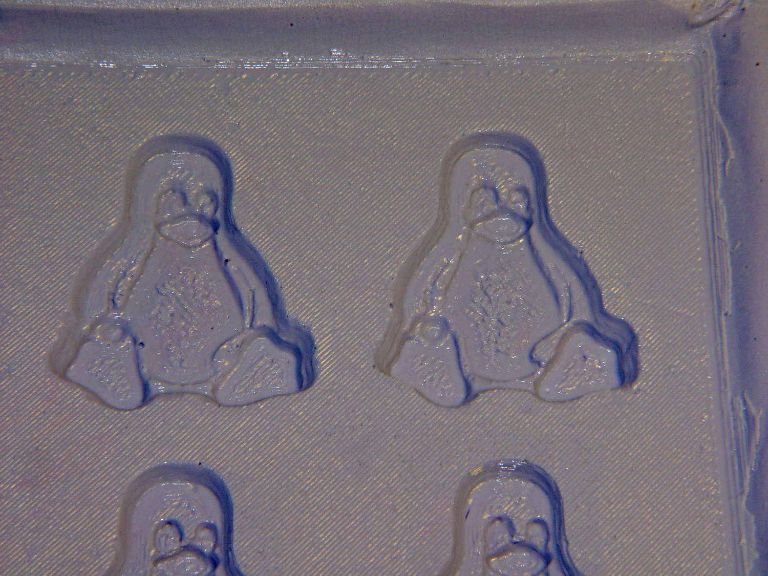
Tux 2×2 mold – negative detail
The hand-knitted texture of the 3D printing process comes through very well, which is a Good Thing in this application. If you don’t like that, you can devote considerable time & attention to removing all traces of the production process.
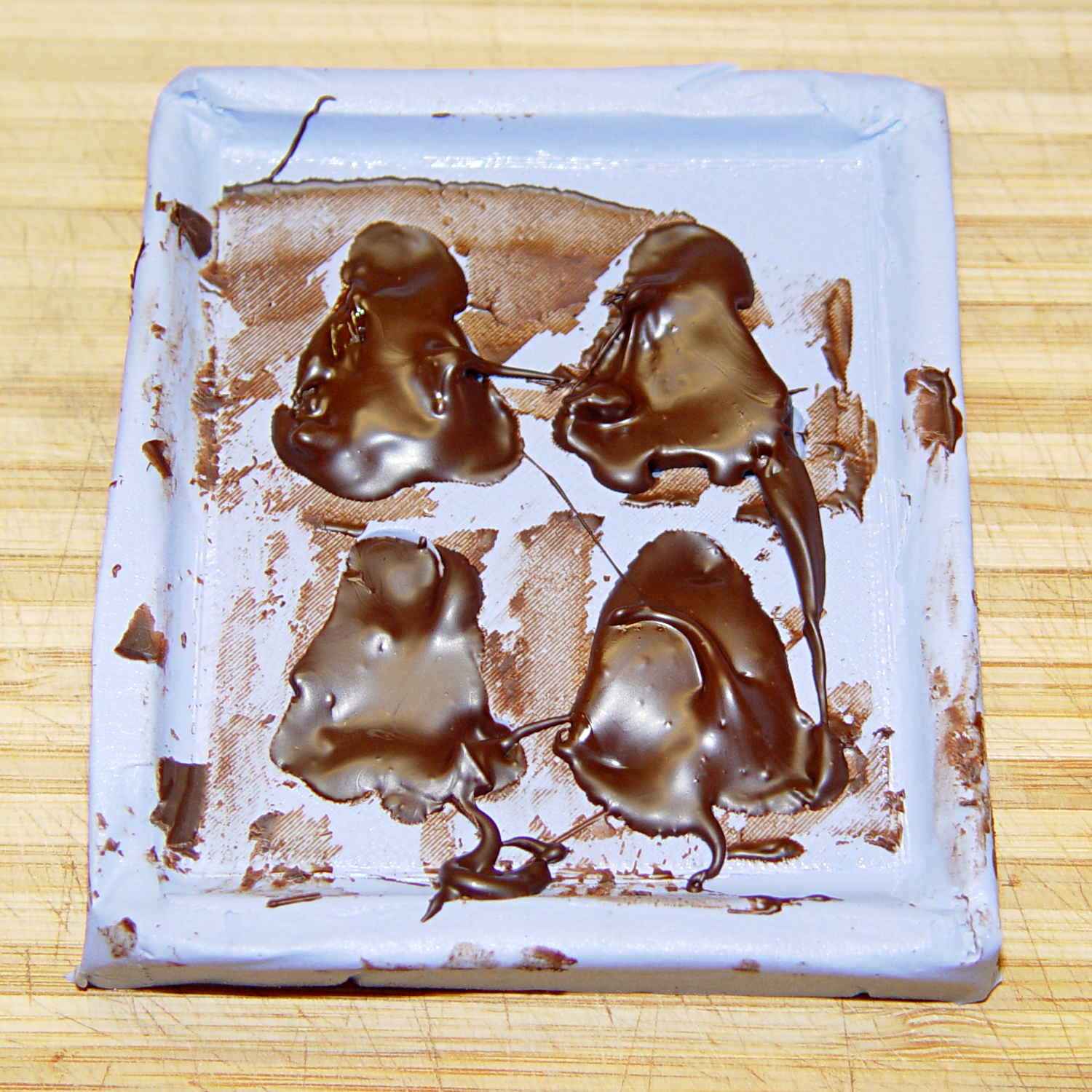
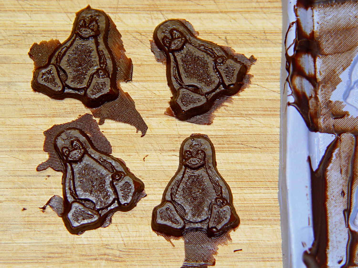
As a proof of concept, I melted and tempered four Dove Dark Chocolate Promises, then poured the chocolate into the cavities:
Tux 2×2 mold – filled
The tempering followed a fairly simple process that worked reasonably well, but the chocolate obviously wasn’t liquid when I poured it. The results looked pretty good, in a textured sort of way:
Tux chocolates – silicone mold
Flushed with success, I tweaked the mold to eliminate the raised lip around the edge, printed another positive plate, mixed up more silicone rubber, paid more attention to getting rid of the bubbles, and got this result:
Tux 2×2 mold 2 – opened
The printed surface still isn’t silicone-tight, which began to puzzle me, but the result looked pretty good.
After some fiddling around, though, I think printing the entire mold array isn’t the way to go. OpenSCAD can handle these 2×2 arrays, but a slightly tweaked Tux model (about which, more later) grossly increased the processing time and memory usage; OpenSCAD (and its CGAL geometry back end) filled all 4 GB of RAM, then blotted up 5 GB of swap space, ran for well over half an hour, and totally locked up the desktop UI for the duration.
It’s certainly infeasible to print the larger array on a sizable base plate that you’d need for a real project. I think printing multiple copies of a single model (duplicating them in the slicer, which is fast & easy), then attaching them to a plain base will work better. There’s no need to print the base plate, either, as a serrated top surface doesn’t buy anything; acrylic (or some such) sheet is cheap, flat, and readily available.
The Bash scripts and OpenSCAD programs below don’t produce exactly the same results you see above, mostly because I screwed around with them while discovering the reasons why doing it this way doesn’t make sense, but they can serve as a starting point if you must convince yourself, too.
This Bash script produces a single positive mold item from a height map image:
// Mold positive pattern from grayscale height map
// Ed Nisley KE4ZNU - March 2014 - adapted from cookie press, added alignment pins

//-----------------
// Mold files

fnMap = "Tux_map.dat";					// override with -D 'fnMap="whatever.dat"'
fnPlate = "Tux_plate.dat";				// override with -D 'fnPlate="whatever.dat"'

DotsPerMM = 3.0;						// overrride with -D DotsPerMM=number

MapHeight = 4.0;						// overrride with -D MapHeight=number

ImageX = 100;							// overrride with -D ImageX=whatever
ImageY = 100;

UsePins = true;

MapScaleXYZ = [1/DotsPerMM,1/DotsPerMM,MapHeight/255];
PlateScaleXYZ = [1/DotsPerMM,1/DotsPerMM,1.0];

echo("Press File: ",fnMap);
echo("Plate File: ",fnPlate);

echo(str("ImageX:",ImageX," ImageY: ", ImageY));
echo(str("Map Height: ",MapHeight));
echo(str("Dots/mm: ",DotsPerMM));
echo(str("Scale Map: ",MapScaleXYZ,"  Plate: ",PlateScaleXYZ));

//- Extrusion parameters - must match reality!

ThreadThick = 0.25;
ThreadWidth = 2.0 * ThreadThick;

//- Buid parameters

PlateThick = IntegerMultiple(1.0,ThreadThick);		// solid plate under press relief

PinOD = 1.75;				// locating pin diameter
PinDepth = PlateThick;		//  ... depth into bottom surface = total length/2
PinOC = 20.0;				// spacing within mold item

echo(str("Pin depth: ",PinDepth," spacing: ",PinOC));

//- Useful info

function IntegerMultiple(Size,Unit) = Unit * ceil(Size / Unit);

HoleWindage = 0.2;

Protrusion = 0.1;						// make holes & unions work correctly

MaxConvexity = 5;						// used for F5 previews in OpenSCAD GUI

ZFuzz = 0.2;							// numeric chaff just above height map Z=0 plane

//-----------------
// Import plate height map, slice off a slab to define outline

module Slab(Thick=1.0) {
	intersection() {
		translate([0,0,Thick/2])
			cube([2*ImageX,2*ImageY,Thick],center=true);
		scale(PlateScaleXYZ)
			difference() {
				translate([0,0,-ZFuzz])
					surface(fnPlate,center=true,convexity=MaxConvexity);
				translate([0,0,-1])
					cube([2*ImageX,2*ImageY,2],center=true);
			}
	}
}

//- Put peg grid on build surface

module ShowPegGrid(Space = 10.0,Size = 1.0) {

	Range = floor(50 / Space);

	for (x=[-Range:Range])
	  for (y=[-Range:Range])
		translate([x*Space,y*Space,Size/2])
			%cube(Size,center=true);
}

//-- convert cylinder to low-count polygon

module PolyCyl(Dia,Height,ForceSides=0) {			// based on nophead's polyholes

  Sides = (ForceSides != 0) ? ForceSides : (ceil(Dia) + 2);

  FixDia = Dia / cos(180/Sides);

  cylinder(r=(FixDia + HoleWindage)/2,
           h=Height,
	   $fn=Sides);
}

//-- Locating pin hole with glue recess
//  Default length is two pin diameters on each side of the split

module LocatingPin(Dia=PinOD,Len=0.0) {

	PinLen = (Len != 0.0) ? Len : (4*Dia);

	translate([0,0,-ThreadThick])
		PolyCyl((Dia + 2*ThreadWidth),2*ThreadThick,4);

	translate([0,0,-2*ThreadThick])
		PolyCyl((Dia + 1*ThreadWidth),4*ThreadThick,4);

	translate([0,0,-(Len/2 + ThreadThick)])
		PolyCyl(Dia,(Len + 2*ThreadThick),4);

}

//- Build it

//ShowPegGrid();

echo("Building mold");
union() {
	difference() {
		Slab(PlateThick + Protrusion);
		if (UsePins)
			for (i=[-1,1])
				translate([0,i*PinOC/2,0])
					rotate(180/4) LocatingPin(Len=2*PinDepth);
	}
	translate([0,0,PlateThick])							// cookie press height map
		scale(MapScaleXYZ)
		difference() {
			translate([0,0,-ZFuzz])
				surface(fnMap,center=true,convexity=MaxConvexity);
			translate([0,0,-1])
				cube([2*ImageX,2*ImageY,2],center=true);
		}
}
This OpenSCAD source code slides a base plate under an array of those mold items, with options for a separate plate using alignment pins or the combined plate-with-molds shown above:
// Positive mold framework for chocolate slabs
// Ed Nisley - KE4ZNU - March 2014

Layout = "FrameMolds";		// FramePins FrameMolds Pin

//- Extrusion parameters must match reality!
//  Print with 2 shells and 3 solid layers

ThreadThick = 0.20;
ThreadWidth = 0.40;

Protrusion = 0.1;			// make holes end cleanly

HoleWindage = 0.2;

//----------------------
// Dimensions

FileName = "Tux_Hi_Profile-positive.stl";	// overrride with -D

Molds = [2,2];					// count of molds within framework

MoldOC = [45.0,50.0];			// on-center spacing of molds
MoldSlab = 1.0;					// thickness of slab under molds

BaseThick = 3.0;

BaseSize = [(Molds[0]*MoldOC[0] + 0),(Molds[1]*MoldOC[1] + 0),BaseThick];
echo(str("Overall base: ",BaseSize));

PinOD = 1.75;					// locating pin diameter
PinLength = 2.0;				//  ... total length
PinOC = 20.0;				// spacing within mold item

//----------------------
// Useful routines

//- Put peg grid on build surface

module ShowPegGrid(Space = 10.0,Size = 1.0) {

	RangeX = floor(100 / Space);
	RangeY = floor(125 / Space);

	for (x=[-RangeX:RangeX])
		for (y=[-RangeY:RangeY])
			translate([x*Space,y*Space,Size/2])
			%cube(Size,center=true);

}

module PolyCyl(Dia,Height,ForceSides=0) {			// based on nophead's polyholes

  Sides = (ForceSides != 0) ? ForceSides : (ceil(Dia) + 2);

  FixDia = Dia / cos(180/Sides);

  cylinder(r=(FixDia + HoleWindage)/2,
           h=Height,
	   $fn=Sides);
}

// Locating pin hole with glue recess
//  Default length is two pin diameters on each side of the split

module LocatingPin(Dia=PinOD,Len=0.0) {

	PinLen = (Len != 0.0) ? Len : (4*Dia);

	translate([0,0,-ThreadThick])
		PolyCyl((Dia + 2*ThreadWidth),2*ThreadThick,4);

	translate([0,0,-2*ThreadThick])
		PolyCyl((Dia + 1*ThreadWidth),4*ThreadThick,4);

	translate([0,0,-(Len/2 + ThreadThick)])
		PolyCyl(Dia,(Len + 2*ThreadThick),4);

}

module LocatingPins(Length) {
	for (i=[-1,1])
	translate([0,i*PinOC/2,0])
		rotate(180/4)
		LocatingPin(Len=Length);
}

//-- import a single mold item

module MoldItem() {

//	intersection() {
		import(FileName,convexity=10);
//		cube([100,100,3],center=true);
//	}
}

//-- Overall frame shape

module Frame() {

//	translate([0,0,BaseSize[2]/2])		// platform under molds
//		cube(BaseSize,center=true);

	difference() {
		hull()
			for (i=[-1,1], j=[-1,1])
				translate([i*BaseSize[0]/2,j*BaseSize[1]/2,0])
					sphere(r=BaseThick);
		translate([0,0,-BaseThick])
			cube(2*BaseSize,center=true);
	}

}

//- Build it

ShowPegGrid();

if (Layout == "Pin")
	LocatingPin(Len=PinLength);

if (Layout == "Frame")
	Frame();

if (Layout == "FramePins")
	difference() {
		Frame();

		translate([-MoldOC[0]*(Molds[0] - 1)/2,-MoldOC[1]*(Molds[1] - 1)/2,0])
			for (i=[0:Molds[0]-1],j=[0:Molds[1]-1])
				translate([i*MoldOC[0],j*MoldOC[1],BaseSize[2]])
					LocatingPins(BaseThick);
	}

if (Layout == "FrameMolds") {
	Frame();
	translate([-MoldOC[0]*(Molds[0] - 1)/2,-MoldOC[1]*(Molds[1] - 1)/2,0])
		for (i=[0:Molds[0]-1],j=[0:Molds[1]-1])
			translate([i*MoldOC[0],j*MoldOC[1],BaseThick - MoldSlab + Protrusion])
			MoldItem();
}
The view through the front window (1950-vintage glass + storm window) at 1/500 s, f/4, ISO 100, auto-exposed to EV 0:
Front yard – normal exposure
The same view, using stacked 2 + 4 + 8 ND filters, at 1/3 s, f/4, ISO 100, auto-exposed to EV 0:
Front yard – ND2-4-8 filters
That blur to the left of the mailbox is a passing car, which is the whole point of heavy ND filtering: you can use absurdly long shutter times and still get a decent exposure.
I cannot explain the fact that the ND filters allegedly reduce the light by 14 stops, but the actual (auto) exposure increases by about 7 stops. They’re cheap non-coated K&F Concept Digital filters, of course, but …
There’s an obvious color shift toward red / magenta.
This is a placeholder so I can pick up the thought later on…