The Smell of Molten Projects in the Morning

Ed Nisley's Blog: Shop notes, electronics, firmware, machinery, 3D printing, laser cuttery, and curiosities. Contents: 100% human thinking, 0% AI slop.

Month: January 2014

  • Whirlpool Refrigerator Drawer Strut Repair

    The strut supporting the two drawers in the bottom of the refrigerator came out in two pieces during a recent cleaning session. To judge from the condition of the joint, I’d done this once before in its history:

    Refrigerator strut - tab clamps
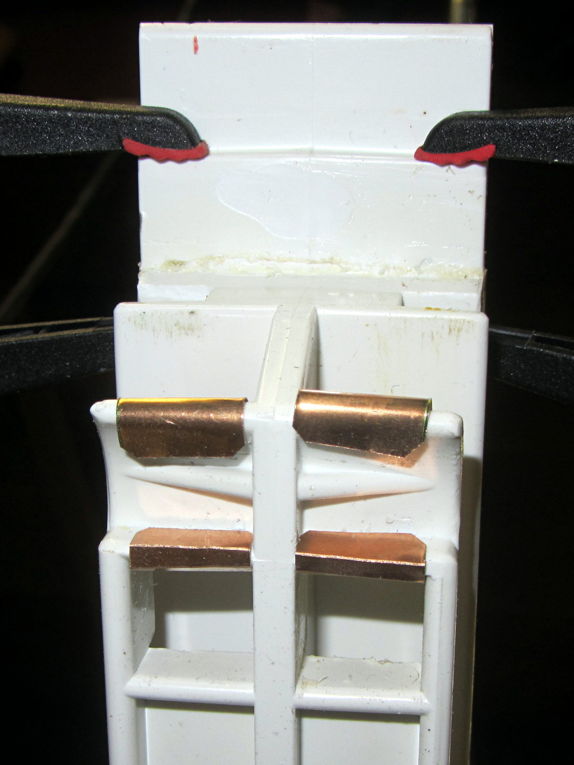
    Refrigerator strut – tab clamps

    That tab inserts into a slot in the front of the elaborate frame that supports the drawers, where it’s captured by a metal bar. Should you lift the rear of the strut without first removing the bar, the tab snaps off at the base. I’ve annotated the top of the strut in the hopes of reminding me the next time around.

    A pair of bumps at the front of the drawer guides should hold the drawers closed, but it’s pretty obvious that’s not working as intended:

    Refrigerator strut - worn retainers
    Refrigerator strut – worn retainers

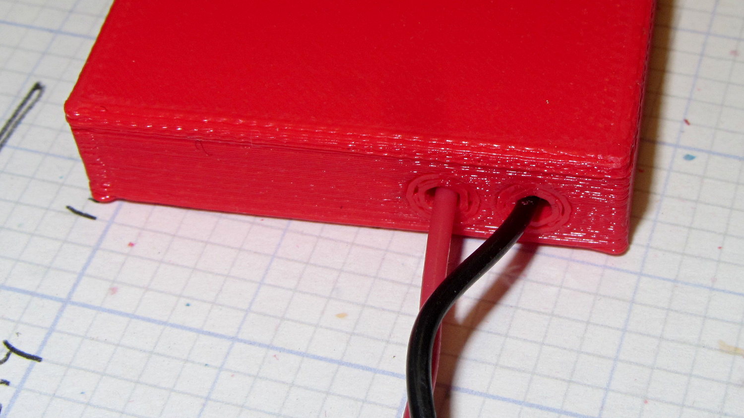
    I shaped strips of phosphor bronze spring stock around the bumps:

    Refrigerator strut - phosphor bronze covers - top
    Refrigerator strut – phosphor bronze covers – top

    The bottom view shows they’re held in place by crimps and a generous dollop of faith:

    Refrigerator strut - phosphor bronze covers - bottom
    Refrigerator strut – phosphor bronze covers – bottom

    That should serve until I know whether the plastic drawer rail will carve through the metal. The drawers slide out with much more enthusiasm now, so it’s a Good Thing until something else breaks.

    Yes, this is the refrigerator with the Freezer Dog

  • Plastic Stress in Polarized Light

    Here’s what the (cracked) faceplate of the FC1002 Frequency Meter looks like, through polarizing filters that reveal the internal stress.

    A circular polarizer screwed on the lens:

    FC1002 Frequency Counter - faceplate - circular polarizer
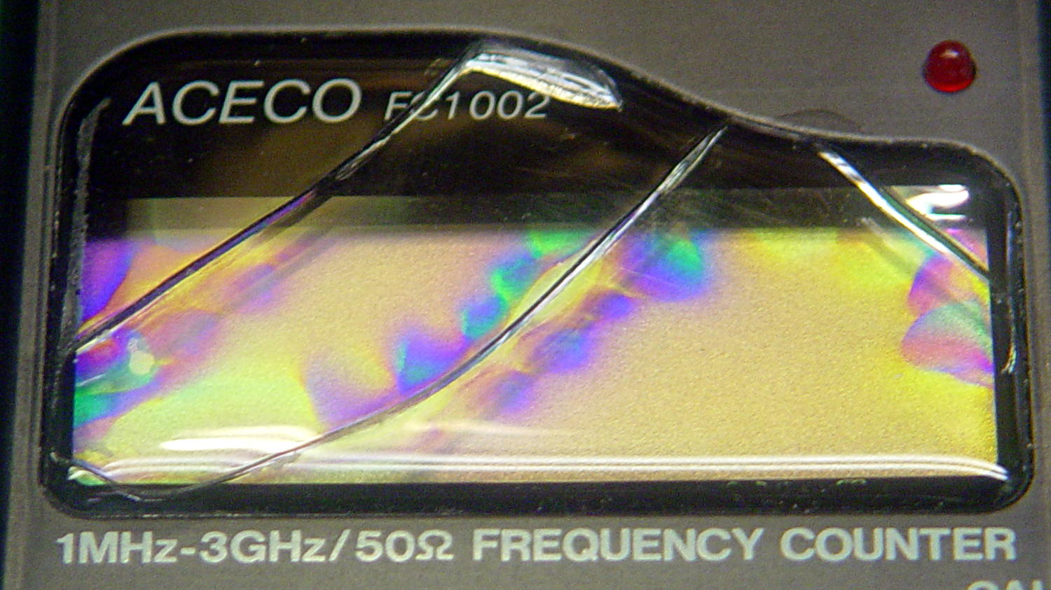
    FC1002 Frequency Counter – faceplate – circular polarizer

    A sheet of linear polarizing film held in front of the lens:

    FC1002 Frequency Counter - faceplate - linear polarizer
    FC1002 Frequency Counter – faceplate – linear polarizer

    For reference, none of the other instrument faceplates on the bench show anything other than uniform gray, with one exception that points directly to the plastic injection point.

    I’d say this plate cracked due to unrelieved internal stresses and not anything I did or didn’t do.

  • Canon NB-6LH Battery Test Fixture

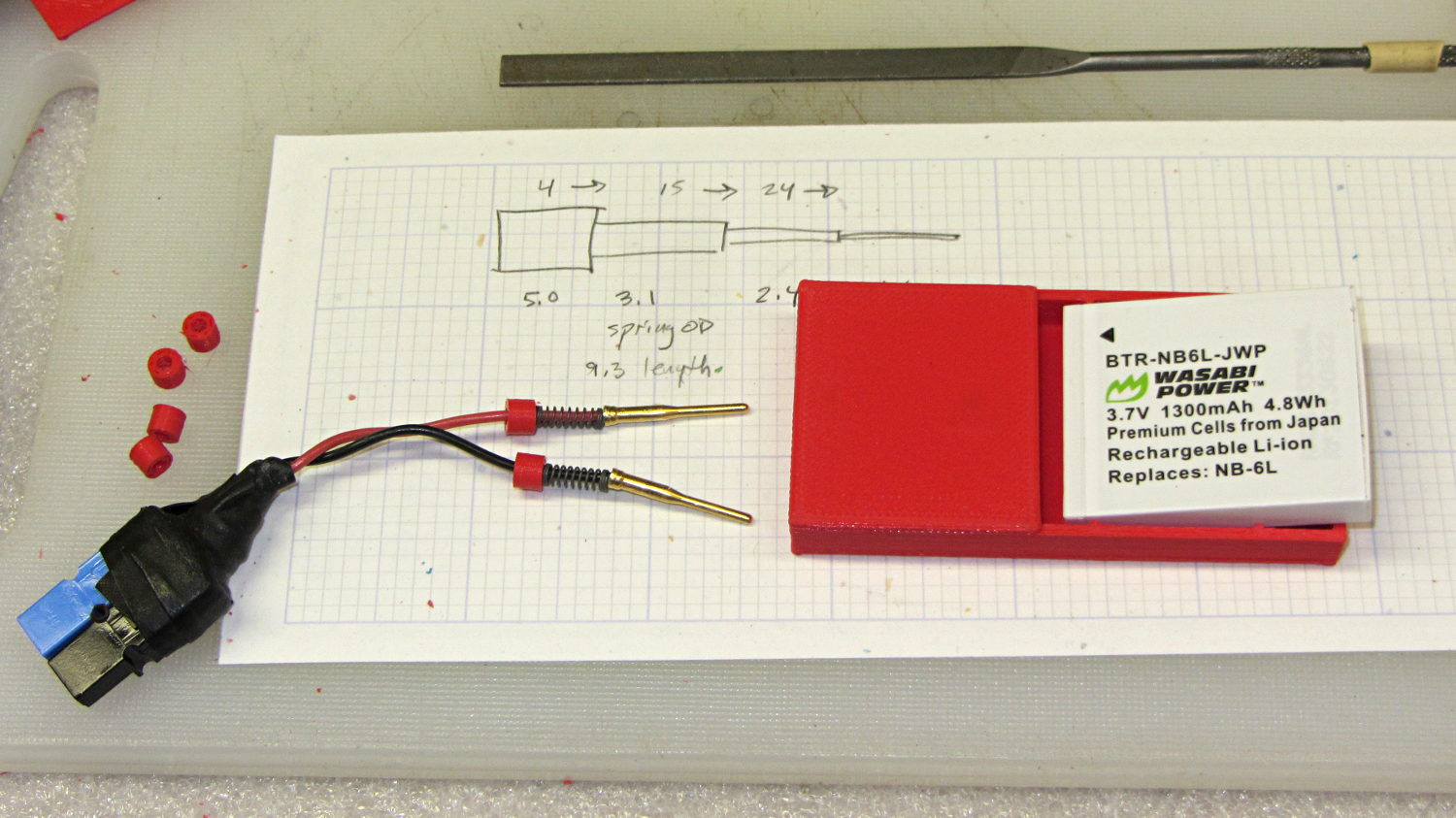
    Our Larval Engineer’s new camera uses Canon NB-6LH batteries, which have exactly the same nominal capacity as the NB-5L batteries for my camera, despite being not quite the same size. I cannot imagine any reason for that, other than brand fractionation, but there it is.

    Fortunately, the sizes are pretty close, so I conjured up another 3D printed battery test fixture for the rundown tests:

    Canon NB-6L battery holder
    Canon NB-6L battery holder

    That hideous Powerpole thing came from one of the AA cell packs I’d been using to power the HTs on the bikes, before switching to lithium battery packs. It’s easier to harvest something suitable than to build a new thing, particularly for such a low duty cycle gadget.

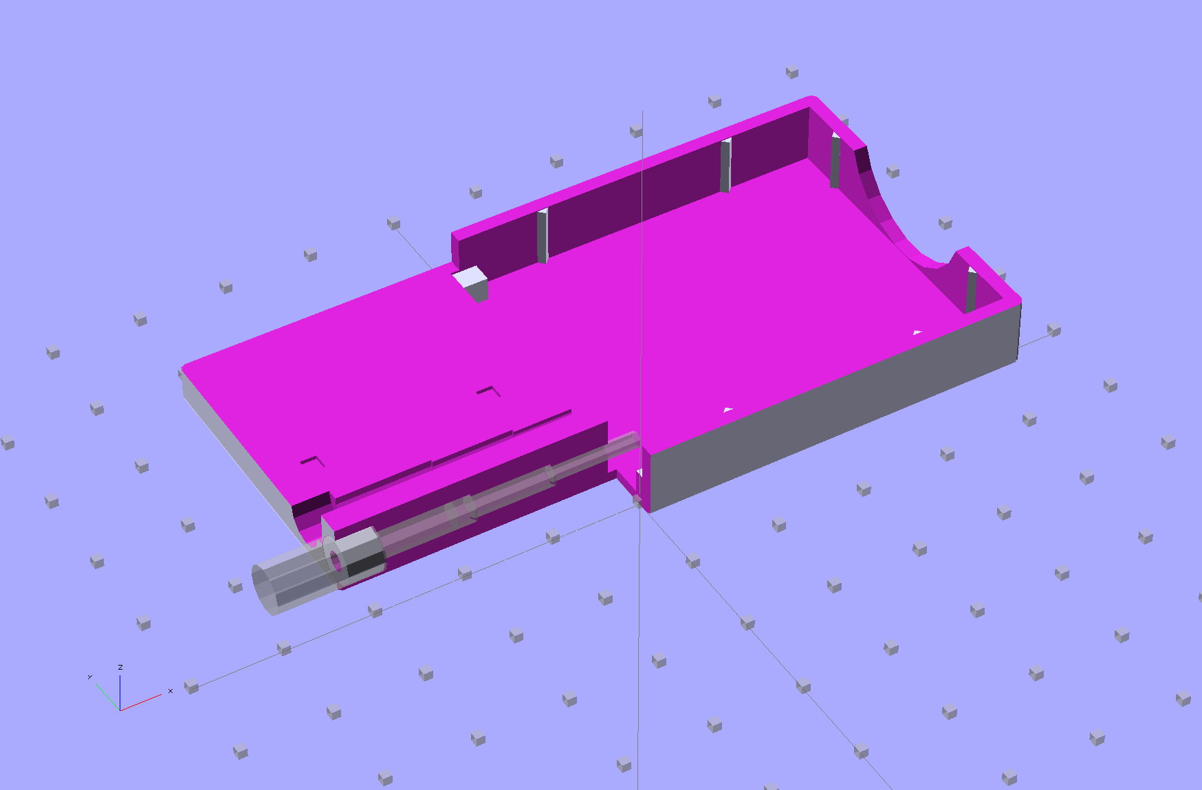
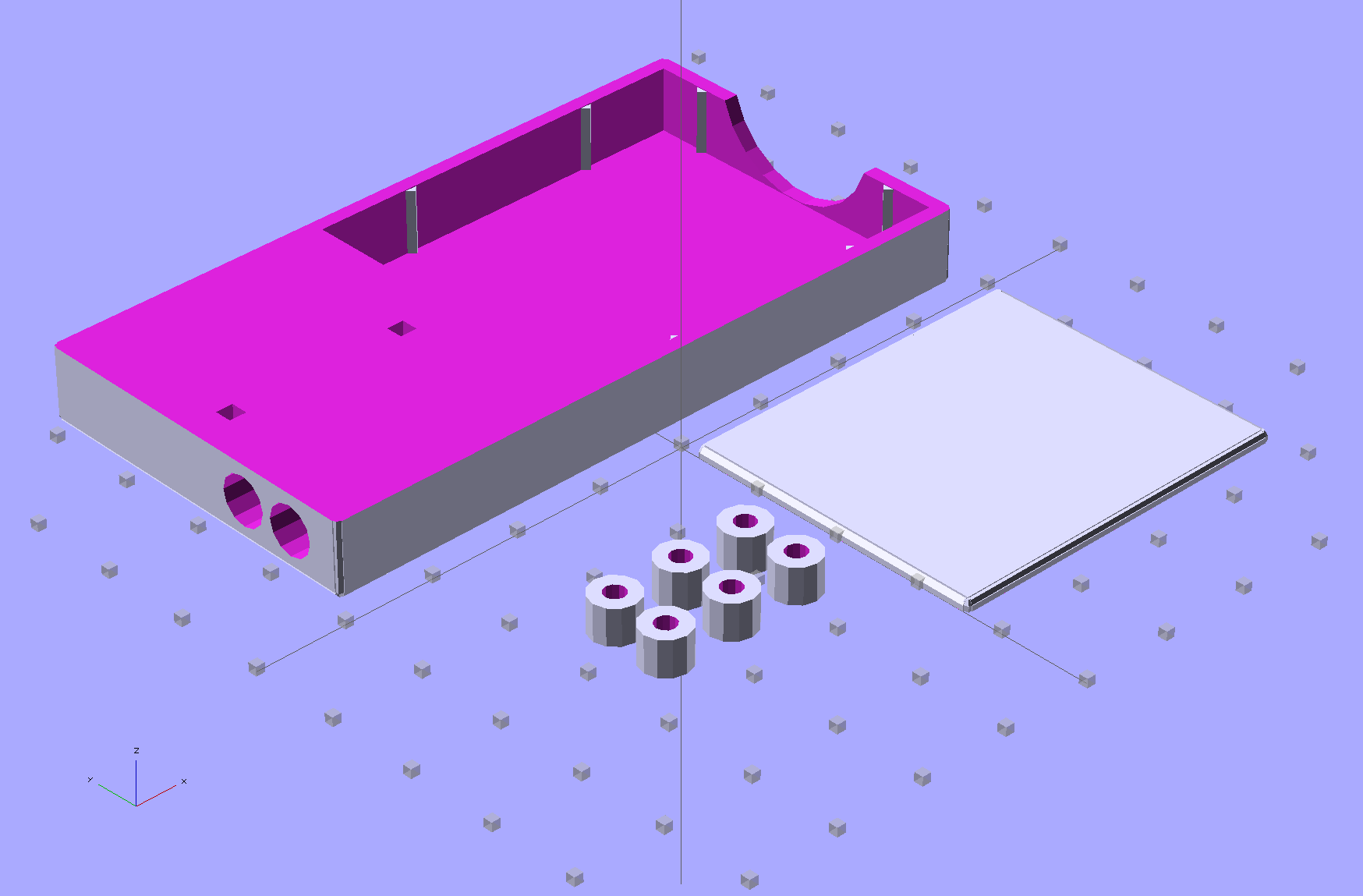
    This view of the solid model shows the contact pins, with the lid floating over its alignment pegs (made from snippets of 1.75 mm filament):

    NB-6L Holder - fit layout
    NB-6L Holder – fit layout

    The pegs simplify gluing the lid in place, a process for which you can never have enough clamps:

    Canon NB-6L holder - lid gluing
    Canon NB-6L holder – lid gluing

    A cutaway shows the stepped holes around the contact pin, with the coil springs being the largest cylinder to the right of the solid-looking plug:

    NB-6L Holder - show layout
    NB-6L Holder – show layout

    The contact pins look like this, at least after one remembers to slide on all the parts before soldering the wires in place:

    Canon NB-6L holder - contact pin detail
    Canon NB-6L holder – contact pin detail

    I filed off the inevitable solder bumps, rounded the butt ends with gentle suasion, and generally tidied the pins up so they’re smooth and symmetrical. The springs don’t have a lot of oomph, so wasting any force on friction or binding is a Bad Thing.

    The holes require reaming with twist drills for a nice slip fit around the pins. The OpenSCAD script prints out the relevant diameters and depths:

    ECHO: "Contact pin tip dia: 1.6"
    ECHO: "Drill depth to taper end: 24.1 -- Dia: 2.4"
    ECHO: "            to ferrule end: 15 -- Dia: 3.1"
    ECHO: "            to plug end: 4 -- Dia: 5.2"
    

    Grab the proper drill in a pin punch, adjust so that length protrudes, and have at it. Making the holes about 0.2 mm larger than nominal works well, although your mileage will definitely vary.

    The build layout includes extra retaining plugs, as they tend to go walkabout under the bench:

    NB-6L Holder - build layout
    NB-6L Holder – build layout

    Add a dab of PVC cement with THF inside the holes and the plugs push firmly into place:

    Canon NB-6L holder - pin retaining plugs - detail
    Canon NB-6L holder – pin retaining plugs – detail

    I loves me my 3D printer…

    The OpenSCAD source code:

    // Holder for Canon NB-6L Li-Ion battery
    // Ed Nisley KE4ZNU January 2013
    
    include <MCAD/boxes.scad>
    
    // Layout options
    
    Layout = "Plugs";					//  Show Build Fit Case Lid Pins Plugs AlignPins
    
    //- Extrusion parameters - must match reality!
    //  Print with +2 shells and 3 solid layers
    
    ThreadThick = 0.20;
    ThreadWidth = 0.40;
    
    HoleWindage = 0.2;
    
    function IntegerMultiple(Size,Unit) = Unit * ceil(Size / Unit);
    
    Protrusion = 0.1;			// make holes end cleanly
    
    inch = 25.4;
    
    BuildOffset = 3.0;			// clearance for build layout
    
    Gap = 8.0;					// separation for Fit parts
    
    //- Battery dimensions - rationalized from several samples
    //  Coordinate origin at battery corner by contact plates on bottom surface
    
    BatteryLength = 42.5;
    BatteryWidth = 35.5;
    BatteryThick =  7.0;
    
    ContactWidth = 2.10;
    ContactLength = 4.10;
    ContactRecess = 0.85;
    
    ContactOC = 3.18;			// center-to-center across contact face
    ContactOffset = 4.45;		// offset from battery edge
    ContactHeight = 3.05;		// offset from battery bottom plane
    
    AlignThick = 2.8;			// alignment recesses on contact face
    AlignDepth = 2.0;			// into face
    AlignWidth1 = 0.7;			// across face at contacts
    AlignWidth2 = 2.0;			//  ... other edge
    
    //- Pin dimensions
    
    PinTipDia = 1.6;
    PinTipLength = 10.0;
    
    PinTaperLength = 2.3;
    
    PinShaftDia = 2.4;
    PinShaftLength = 6.8;
    
    PinFerruleDia = 3.1;
    PinFerruleLength = 2.0;
    
    PinLength = PinTipLength + PinTaperLength + PinShaftLength + PinFerruleLength;
    
    ExtendRelax = 1.5 + ContactRecess;		// pin extension when no battery is present
    ExtendOvertravel = 1.0;					//  ... beyond engaged position
    
    //- Spring dimensions
    
    SpringDia = 3.1;						// coil OD
    SpringMax = 9.3;
    SpringLength = SpringMax - 0.3;			// slightly compressed
    SpringMin = 4.5;
    
    SpringPlugOD = IntegerMultiple(5.0,ThreadWidth);		// plug retaining the spring
    SpringPlugID = 2.0;
    SpringPlugLength = IntegerMultiple(4.0,ThreadWidth);
    SpringPlugSides = 3*4;
    
    SpringTravel = ExtendRelax + ExtendOvertravel;
    
    //- Holder dimensions
    
    GuideRadius = ThreadWidth;						// friction fit ridges
    GuideOffset = 10;
    WallThick = 4*ThreadWidth;						// holder sidewalls
    
    BaseThick = 6*ThreadThick;			// bottom of holder to bottom of battery
    TopThick = 6*ThreadThick;			// top of battery to top of holder
    
    ThumbRadius = 10.0;			// thumb opening at end of battery
    
    CornerRadius = 3*ThreadThick;			// nice corner rounding
    
    CaseLength = SpringPlugLength + SpringLength + PinLength - ExtendRelax
    			+ BatteryLength + GuideRadius + WallThick;
    CaseWidth = 2*WallThick + 2*GuideRadius + BatteryWidth;
    CaseThick = BaseThick + BatteryThick + TopThick;
    
    AlignPinOD = 1.75;			// lid alignment pins - filament snippets
    AlignPinLength = 5.0;
    AlignPinInset = 7.0;
    
    //- XY origin at front left battery corner, Z on platform below that
    
    CaseLengthOffset = -(SpringPlugLength + SpringLength + PinLength - ExtendRelax);
    CaseWidthOffset = -(WallThick + GuideRadius);
    CaseThickOffset = BaseThick;
    
    LidLength = ExtendRelax - CaseLengthOffset;
    
    echo(str("Contact pin tip dia: ",PinTipDia));
    echo(str("Drill depth to taper end: ",
    		 (SpringPlugLength + SpringLength + PinFerruleLength + PinShaftLength + PinTaperLength),
    		 " -- Dia: ",PinShaftDia));
    echo(str("            to ferrule end: ",
    		  (SpringPlugLength + SpringLength + PinFerruleLength),
    		 " -- Dia: ",PinFerruleDia));
    echo(str("            to plug end: ",SpringPlugLength,
    		 " -- Dia: ",SpringPlugOD));
    
    //----------------------
    // Useful routines
    
    module PolyCyl(Dia,Height,ForceSides=0) {			// based on nophead's polyholes
    
      Sides = (ForceSides != 0) ? ForceSides : (ceil(Dia) + 2);
    
      FixDia = Dia / cos(180/Sides);
    
      cylinder(r=(FixDia + HoleWindage)/2,
               h=Height,
    	   $fn=Sides);
    }
    
    module ShowPegGrid(Space = 10.0,Size = 1.0) {
    
      Range = floor(50 / Space);
    
    	for (x=[-Range:Range])
    	  for (y=[-Range:Range])
    		translate([x*Space,y*Space,Size/2])
    		  %cube(Size,center=true);
    
    }
    
    //-------------------
    
    //-- Guides for tighter friction fit
    
    module Guides() {
      	  translate([GuideOffset,-GuideRadius,CaseThickOffset])
    		PolyCyl(2*GuideRadius,(BatteryThick - Protrusion),4);
    	  translate([GuideOffset,(BatteryWidth + GuideRadius),CaseThickOffset])
    		PolyCyl(2*GuideRadius,(BatteryThick - Protrusion),4);
    	  translate([(BatteryLength - GuideOffset),-GuideRadius,CaseThickOffset])
    		PolyCyl(2*GuideRadius,(BatteryThick - Protrusion),4);
    	  translate([(BatteryLength - GuideOffset),(BatteryWidth + GuideRadius),CaseThickOffset])
    		PolyCyl(2*GuideRadius,(BatteryThick - Protrusion),4);
    	  translate([(BatteryLength + GuideRadius),GuideOffset/2,CaseThickOffset])
    		PolyCyl(2*GuideRadius,(BatteryThick - Protrusion),4);
    	  translate([(BatteryLength + GuideRadius),(BatteryWidth - GuideOffset/2),CaseThickOffset])
    		PolyCyl(2*GuideRadius,(BatteryThick - Protrusion),4);
    
    }
    
    //-- Contact pins (holes therefore)
    
    module PinShape() {
    
      union() {
    	cylinder(r=(PinTipDia + HoleWindage)/2,h=(PinTipLength + Protrusion),$fn=6);
    
    	translate([0,0,PinTipLength])
    	  cylinder(r=(PinShaftDia + HoleWindage)/2,
    			   h=(PinTaperLength + PinShaftLength + Protrusion),$fn=6);
    
    	translate([0,0,(PinLength - PinFerruleLength)])
    	  cylinder(r=(PinFerruleDia + HoleWindage)/2,
    				h=(PinFerruleLength + Protrusion),$fn=6);
    
    	translate([0,0,(PinLength)])
    	  cylinder(r=(SpringDia + HoleWindage)/2,
    				h=(SpringLength + Protrusion),$fn=6);
    
    	translate([0,0,(PinLength + SpringLength - HoleWindage)])	// windage for hole length
    	  cylinder(r=(SpringPlugOD + HoleWindage)/2,h=3*SpringPlugLength,$fn=SpringPlugSides);
    
    //	  translate([0,0,(PinLength + SpringLength + SpringPlugLength)])
    //	  cylinder(r=(SpringPlugOD + HoleWindage)/2,h=2*SpringPlugLength,$fn=SpringPlugSides);	// extend hole
      }
    
    }
    
    module PinAssembly() {
    
      translate([ExtendRelax,ContactOffset,CaseThickOffset + ContactHeight]) {
    	rotate([0,270,0]) {
    	  PinShape();												// pins
    	  translate([0,(2*ContactOC),0])
    		PinShape();
    	}
      }
    
    }
    
    //-- Alignment pins
    
    module AlignPins() {
    
    	for (x=[-1,1])
    		translate([x*(LidLength - 2*AlignPinInset)/2,0,0])
    			rotate(45)
    			PolyCyl(AlignPinOD,AlignPinLength);
    }
    
    //-- Case with origin at battery corner
    
    module Case() {
    
      difference() {
    
    	union() {
    
    	  difference() {
    		translate([(CaseLength/2 + CaseLengthOffset),
    				  (CaseWidth/2 + CaseWidthOffset),
    				  (CaseThick/2)])
    		  roundedBox([CaseLength,CaseWidth,CaseThick],CornerRadius); 	// basic case shape
    
    		translate([-ExtendOvertravel,-GuideRadius,CaseThickOffset])
    		  cube([(BatteryLength + GuideRadius + ExtendOvertravel),
    				(BatteryWidth + 2* GuideRadius),
    				(BatteryThick + Protrusion)]);						// battery space
    
    	  }
    
    	  Guides();
    
    	  translate([-ExtendOvertravel,-GuideRadius,BaseThick])
    		cube([(AlignDepth + ExtendOvertravel),
    			  (AlignWidth1 + GuideRadius),
    			  AlignThick]);											// alignment blocks
    	  translate([-ExtendOvertravel,
    				 (BatteryWidth - AlignWidth2),
    				 BaseThick])
    		cube([(AlignDepth + ExtendOvertravel),
    			  (AlignWidth2 + GuideRadius),
    			  AlignThick]);
    
    	}
    
    	translate([(-ExtendOvertravel),
    			   (CaseWidthOffset - Protrusion),
    			   (CaseThickOffset + BatteryThick)])
    	  cube([CaseLength,
    		    (CaseWidth + 2*Protrusion),
    		    (TopThick + Protrusion)]);								// battery access
    
    	translate([(CaseLengthOffset - Protrusion),
    			   (CaseWidthOffset - Protrusion),
    			   (CaseThickOffset + BatteryThick)])
    	  cube([(CaseLength + 2*Protrusion),
    		    (CaseWidth + 2*Protrusion),
    		    (TopThick + Protrusion)]);								// battery insertion allowance
    
    	translate([(BatteryLength - Protrusion),
    			    (CaseWidth/2 + CaseWidthOffset),
    			    (CaseThickOffset + ThumbRadius)])
    	  rotate([90,0,0])
    		rotate([0,90,0])
    		  cylinder(r=ThumbRadius,
    				   h=(WallThick + GuideRadius + 2*Protrusion),
    				   $fn=22);											// remove thumb notch
    
    	PinAssembly();
    
    	translate([-LidLength/2,BatteryWidth/2,CaseThick - TopThick - (AlignPinLength - TopThick/2)])
    		AlignPins();
      }
    
    }
    
    module Lid() {
    
      difference() {
    	translate([0,0,(CaseThick/2 - BaseThick - BatteryThick)])
    	  roundedBox([LidLength,
    				 CaseWidth,CaseThick],CornerRadius);
    
    	translate([0,0,-(CaseThick/2)])
    	  cube([(LidLength + 2*Protrusion),
    		    (CaseWidth + 2*Protrusion),
    		    (CaseThick)],center=true);
    
    	translate([-ExtendRelax,0,-(AlignPinLength - TopThick/2)])
    		AlignPins();
      }
    
    }
    
    module PlugShape() {
    
      difference() {
    	cylinder(r=SpringPlugOD/2,h=SpringPlugLength,$fn=SpringPlugSides);
    	translate([0,0,-Protrusion])
    	  PolyCyl(SpringPlugID,(SpringPlugLength + 2*Protrusion),SpringPlugSides);
      }
    }
    
    module Plugs() {
      translate([0,ContactOC,0])
    	PlugShape();
      translate([0,-ContactOC,0])
    	PlugShape();
    }
    
    //-------------------
    // Build it!
    
    ShowPegGrid();
    
    if (Layout == "Case")
      Case();
    
    if (Layout == "Lid")
      Lid();
    
    if (Layout == "Plugs")
    	for (i=[-1:1])
    		translate([i*1.5*SpringPlugOD,0,0])
    			Plugs();
    
    if (Layout == "Pins")
      PinShape();
    
    if (Layout == "AlignPins")
      AlignPins();
    
    if (Layout == "Show") {								// reveal pin assembly
      difference() {
    	Case();
    
    	translate([(CaseLengthOffset - Protrusion),
    			   (CaseWidthOffset - Protrusion + WallThick + ContactOffset + ContactOC),
    			   (BaseThick + ContactHeight)])
    	  cube([(-CaseLengthOffset + Protrusion),
    			 (CaseWidth + 2*Protrusion),
    			 CaseThick + BaseThick - ContactHeight + Protrusion]);
    
    	translate([(CaseLengthOffset - Protrusion),
    			   (CaseWidthOffset - Protrusion),
    			   -Protrusion])
    	  cube([(-CaseLengthOffset + Protrusion),
    			 (WallThick + GuideRadius + ContactOffset + Protrusion),
    			 CaseThick]);
      }
    
      translate([ExtendRelax,ContactOffset,(CaseThickOffset + ContactHeight)]) {	// pins
    	rotate([0,270,0]) {
    	  %PinShape();
    //	  translate([0,(2*ContactOC),0])
    //		%PinShape();
    	}
      }
    
      translate([CaseLengthOffset,ContactOffset,(CaseThickOffset + ContactHeight)])
    	rotate([0,90,0])
    	  PlugShape();
    }
    
    if (Layout == "Build") {
      translate([-(CaseLength/2 + CaseLengthOffset),-(CaseWidthOffset - BuildOffset),0])
    	Case();
      translate([CaseWidth/2,(CaseLengthOffset/2 - BuildOffset),0])
    	rotate([0,0,90])
    	  Lid();
      for (i=[-1:1])
    	translate([CaseLengthOffset/2 + i*1.5*SpringPlugOD,-CaseWidth/2,0])
    		Plugs();
    }
    
    if (Layout == "Fit") {
      Case();
      translate([(-LidLength/2 + ExtendRelax),
    			(CaseWidth/2 + CaseWidthOffset),
    			(BaseThick + BatteryThick + Gap)])
    	  Lid();
      translate([ExtendRelax,ContactOffset,CaseThickOffset + ContactHeight]) {	// pins
    	rotate([0,270,0]) {
    	  %PinShape();
    	  translate([0,(2*ContactOC),0])
    		%PinShape();
    	}
      }
    
      translate([CaseLengthOffset,
    			(ContactOffset + ContactOC),
    			(CaseThickOffset + ContactHeight)])
      rotate([0,90,0])
    	Plugs();
    
      translate([-LidLength/2,BatteryWidth/2,CaseThick])
    #	AlignPins();
    
    }
    
    
  • Thing-O-Matic 286 Conversion: Marlin Firmware Tweaks

    Azteeg X3 - inside TOM286
    Azteeg X3 – inside TOM286

    Although the TOM286 conversion won’t need any fancy firmware, I forked Marlin’s Github repository and created a TOM286 branch based on the Marlin_v1 branch for the Azteeg X3 modifications; in theory, we can blend in future Marlin updates without too much hassle.

    The Pronterface serial port tops out at 115200, so that’s a mandatory change right up front. [grin]

    Marlin has a motherboard definition for an Azteeg X3 (type 67), but without the optional thermocouple inputs. I added motherboard 671, following the lead of the Megatronics board definitions (types 70, 701, and 702). In addition to the changes below, any test for motherboard 67 now includes 671, as the other pins and suchlike (should) be the same.

    Motherboard 671 selects new pin definitions for the temperature inputs in pins.h:

      #if MOTHERBOARD == 671
    	#define TEMP_0_PIN         11   // TC1 on shield
    	#define TEMP_1_PIN          4   // TC2 on shield
    	#define TEMP_2_PIN         13   // T0 thermistor on Azteeg X3 motherboard
      #else
        #define TEMP_0_PIN         13   // ANALOG NUMBERING
        #define TEMP_1_PIN         15   // ANALOG NUMBERING
        #define TEMP_2_PIN         -1   // ANALOG NUMBERING
    #endif
    

    There’s now a TCOUPLE_AMP_TYPE definition in Configuration.h to select AD595 or AD849x thermocouple interfaces:

    // Thermocouple sensor amplifier type
    //  0 = AD595 gain = 10 mV/C
    //  1 = AD849[4567] gain = 5 mV/C
    
    #define TCOUPLE_AMP_TYPE 1
    

    That picks the proper offset and gain definitions in Configuration_adv.h:

    // The AD849[4567] has 5 mv/C gain, half that of the AD595, and requires _GAIN = 2
    
    #if TCOUPLE_AMP_TYPE == 1
      #define TEMP_SENSOR_AD595_OFFSET 0.0
      #define TEMP_SENSOR_AD595_GAIN   2.0
    #else
      #define TEMP_SENSOR_AD595_OFFSET 0.0
      #define TEMP_SENSOR_AD595_GAIN   1.0
    #endif
    

    With those in hand, these temperature sensor selections in Configuration.h will work:

    #define TEMP_SENSOR_0 -1
    #define TEMP_SENSOR_1 0
    #define TEMP_SENSOR_2 0
    #define TEMP_SENSOR_BED 1
    

    I tweaked the temperature limits and preheat settings; the absolute minimum temperatures are now 10 °C, although I have not verified that a disconnected thermocouple or thermistor will actually trip that limit.

    Given the completely arbitrary stepper motor wiring connections, I set all the direction inversions to false and then swapped wires to make the motors turn in the proper direction.

    I enabled EEPROM_SETTINGS, but haven’t verified that values can actually store and recall themselves.

    The XYZ=0 origin is in the middle of the platform, just where I like it, but that will require some fine tuning:

    // Travel limits after homing
    #define X_MAX_POS 55
    #define X_MIN_POS -50
    #define Y_MAX_POS 60
    #define Y_MIN_POS -60
    #define Z_MAX_POS 120
    #define Z_MIN_POS 0
    

    I think it’s possible to use the Z_SAFE_HOMING position to force Z-minimum homing on the platform height switch I built for the original firmware, but that operation also seems to be tied in with the three-point auto-leveling firmware and rotating switch assembly. Right now, the firmware homes to the Z-max switch as a stock Thing-O-Matic should, but I’ve never liked that arrangement; don’t start with me, you know how I get.

    I backed the speeds and accelerations down from the values I’d been using, mostly because the driver hardware and currents are different:

    // Computing steps/mm
    // for XY = (motor steps/rev * microstepping) / (pulley teeth * tooth pitch)
    // for  Z = (motor steps/rev * microstepping) / (screw lead) // for  E = (motor steps/rev * microstepping) / (gear ratio * drive circumference) //  make sure ratios use floating point to avoid integer division!
    #define DEFAULT_AXIS_STEPS_PER_UNIT   {(200*16)/(17*2.0), (200*16)/(17*2.0), (200*8)/8.0, (200*4)/((7*30.23)/51)}
    #define DEFAULT_MAX_FEEDRATE          {5000/60, 5000/60, 1500/60, 4000/60}    // (mm/sec)
    #define DEFAULT_MAX_ACCELERATION      {5000, 2500, 1000, 250}    // X, Y, Z, E maximum start speed for accelerated moves. E default values are good for skeinforge 40+, for older versions raise them a lot.
    
    #define DEFAULT_ACCELERATION          10000   // X, Y, Z and E max acceleration in mm/s^2 for printing moves
    #define DEFAULT_RETRACT_ACCELERATION  10000   // X, Y, Z and E max acceleration in mm/s^2 for retracts


    I’m not sure how to calculate the “jerk” settings, but taken as the maximum un-accelerated speed, these seem conservative:

    // The speed change that does not require acceleration (i.e. the software might assume it can be done instantaneously)
    #define DEFAULT_XYJERK                25    // (mm/sec)
    #define DEFAULT_ZJERK                 5    // (mm/sec)
    #define DEFAULT_EJERK                 5     // (mm/sec)
    

    More tuning is in order; that should at least start it up.

  • Canon vs. Wasabi NB-6LH Batteries

    Our Larval Engineer reported that her camera, which is my old Casio pocket camera, has begun fading away, so we’re getting her a shiny new camera of her very own. Being a doting father, I picked up a pair of Wasabi NB-6L batteries (and a charger, it not costing much more for the package) so she’s never without electrons, and did the usual rundown test on all three batteries:

    Canon NB-6L - 2014 OEM vs Wasabi
    Canon NB-6L – 2014 OEM vs Wasabi

    Fairly obviously, the Wasabi batteries aren’t first tier products, but they’re definitely better than that bottom-dollar crap from eBay.

  • Ubuntu 10.04LTS vs Foxconn D510 NIC: FAIL

    For some unknown reason, one of the very rare updates to the Ubuntu 10.04 LTS infrastructure (for LinuxCNC 2.5.3 on my Foxconn D510 box, driving the Sherline mill) stopped supporting the system board’s built-in NIC: networking stopped working. The only symptom was that the NIC didn’t respond and all the usual tricks were unproductive.

    After some fruitless searching, I took the easy way out:

    NIC added to Foxconn D510 PC
    NIC added to Foxconn D510 PC

    That’s the backside of an ancient NIC using the classic Tulip driver. It used to have a full-size bracket, which I chopped off, bent, and filed to suit, much as with that one in the D525.

    Fired it up, the kernel automagically picked the proper driver, and networking Just Worked again.

    There. Fixed that…

  • Unsealed Camera Box

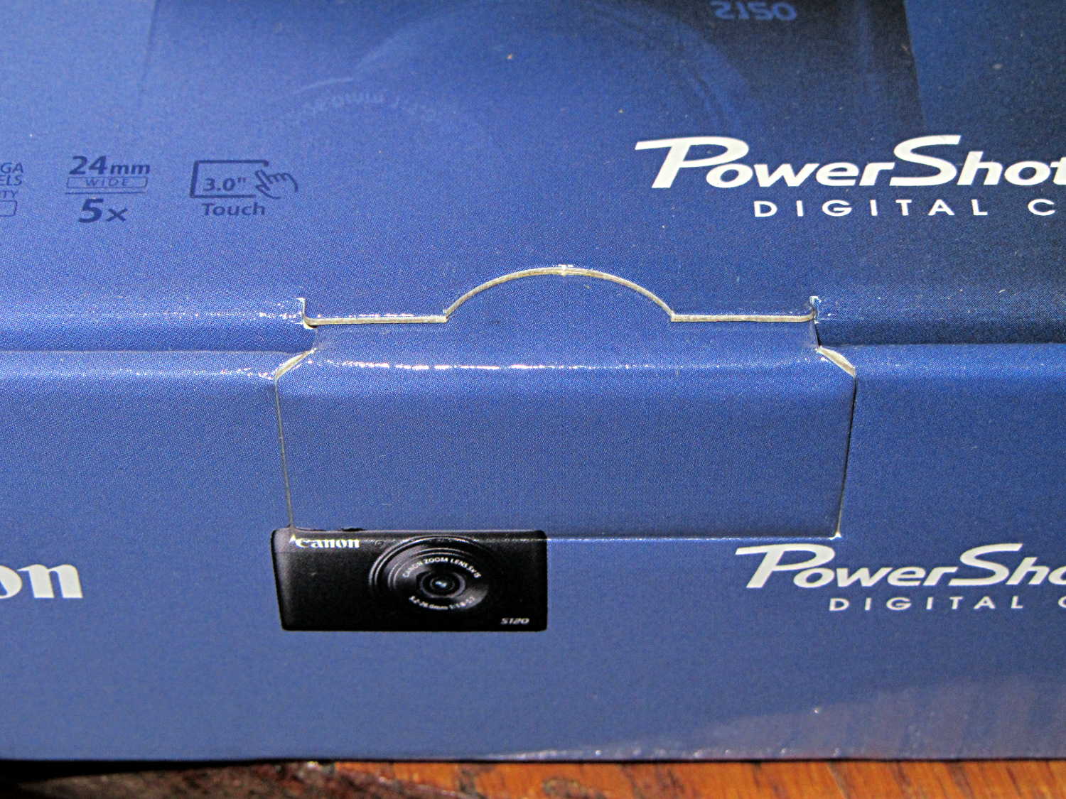
    Used to be, back in the day, that when you got a box full of shiny new electronics, it bore stickers: “Do not accept if seal is broken” or “Factory sealed” or “Genuine product” or something like that. When you slit the seal, you had some confidence that the last person to look in the box sat at the end of their production line; I’ll grant you that counterfeit stickers have become cheap & readily available, but it’s the principle of the thing.

    Nowadays, a shiny new Canon camera arrives in a box with a tab tucked into a slit:

    Canon Camera box - unopened and unsealed
    Canon Camera box – unopened and unsealed

    The box looked unopened and everything inside seemed in order, but … even though I’d seen this before on other cameras, it’s still disconcerting.

    I’m unsure of the story about laminate flooring in the camera box.