As mentioned there, the usual eBay vendor shipped HB-415M drivers instead of the advertised 2M415 drivers. Based on the Chinese datasheet and some poking around, I got a test setup working with a bench supply, a signal generator, and a NEMA 17 stepper motor with 2 Ω windings.
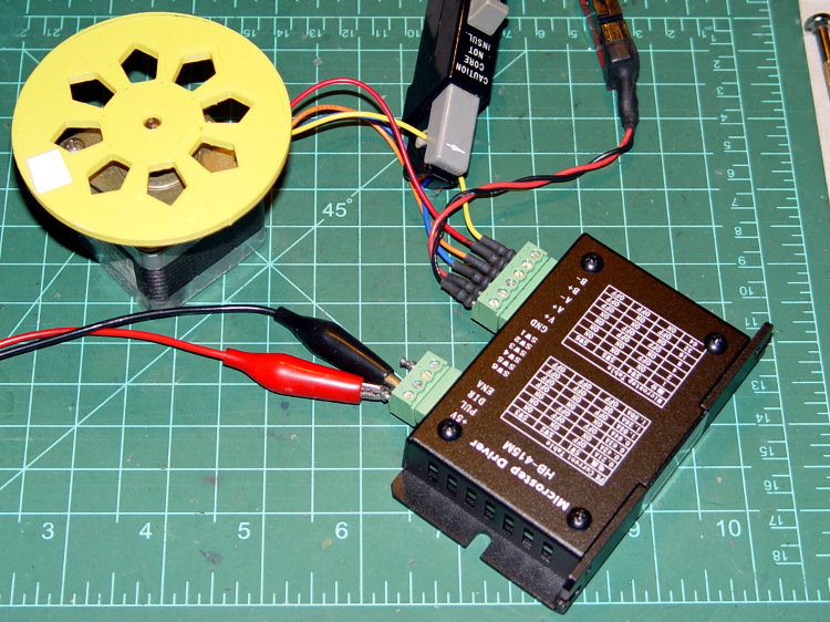
Yes, it’s that stepper motor and interrupter wheel.
First observation: the ENA input is active high. Pulling it low to turn on the optocoupler disables the drive output, which is exactly the opposite of what’s shown in the datasheet, which means that the driver will run quite happily with nothing connected to the ENA pin. The optoisolator current runs about 11 mA from a 5 V supply, close enough to the 10 mA typical spec, but the signal generator thinks it’s providing a TTL pulse output.
Second observation: the driver’s actual winding current doesn’t match the DIP switch setting.
Here’s the 1/8 microstep winding current for the 1.50 A peak setting, with a 0.5 A/div vertical calibration:
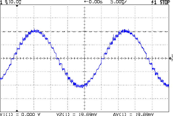
Sure looks like 1 A peak, doesn’t it?
The ratio seems close to 0.707 and remains consistent across all current settings, so I’d lay long money that the designer confused “peak” and “RMS” values, then figured the current sense resistor or chose the internal coefficients to produce the corresponding RMS current for the peak value.
The reduced current produces not very much torque at all; negotiations are in progress for a partial refund based on eBay’s “item not as described” process…

Comments
3 responses to “HB-415M Stepper Driver Measurements”
[…] well, the peak current isn’t as high as they claim, so it all probably works out in the […]
[…] you saw earlier the low-speed waveform looked reasonably good, although the HB-415M driver produces only 71% of its rated current (so it’s actually 1 A peak, not the 1.5 A in the […]
[…] with that setup on the bench, I ran a simple experiment with current, temperature, and heat transfer. Most DIY 3D […]