Ed Nisley's Blog: Shop notes, electronics, firmware, machinery, 3D printing, laser cuttery, and curiosities. Contents: 100% human thinking, 0% AI slop.
Tag: Thing-O-Matic
Using and tweaking a Makerbot Thing-O-Matic 3D printer
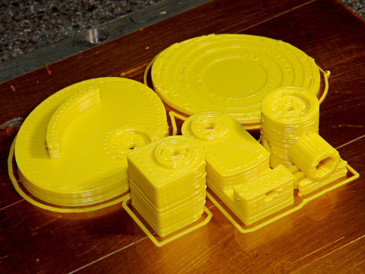
Printing went smoothly after two preliminary passes to work out the sizes and alignments; this is the second pass, which you can tell because the mirror shoulder has three supports instead of the two shown in the solid model:
Mirror mount parts on build plate
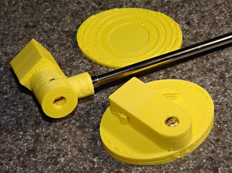
One view of the parts, with the mirror shaft in place:
Mirror mount partial assembly – top
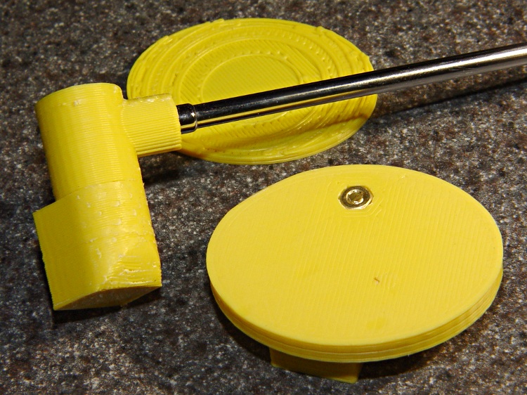
Another view, showing the bottom of the Elevation Plate with the recessed nut:
Mirror mount parts partial assembly – bottom
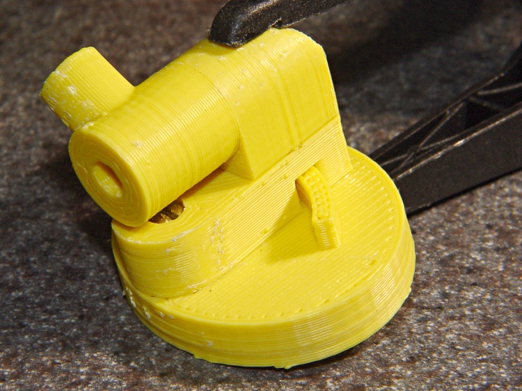
Assembling the two glue joints required an overnight clamping:
Mirror mount – glued and clamped
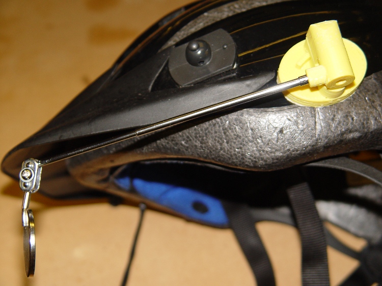
Then a layer of double-stick foam tape affixes it firmly to the helmet:
Mirror mount – on helmet
It’s a bit too big and way ugly, but works pretty much as expected.
Two lengths of heatshrink tubing now lock the mirror shaft sections in place; they tended to rotate slightly under normal vibration.
The OpenSCAD code and model have a few modifications from this object. The next one won’t have the third section of mirror shaft, which makes the shoulder and Az Mount smaller, and the Az Mount is 1 mm closer to the El Body. That shaves a few millimeters off the whole thing.
The mirror clamp out there on the end is much too large and has too many fiddly parts. I think a little printed doodad would work, but that’s in the nature of fine tuning.
After a bit of OpenSCAD twiddling, those doodles turned into a printable model. This view shows what it looks like all neatly assembled:
The tiny hole on the top of the Elevation Body accepts a 2-56 setscrew that grabs the arc protruding from the Elevation Plate and locks the up-and-down setting. The Azimuth Mount pivots on the 3-48 screw holding it to the Elevation Mount.
Both of those pivots must be loose enough to move when you bump the mirror and tight enough to stay put in normal use. It’s a delicate balance and I’m not convinced this will work for the long term, but it’s a brassboard.
The 2-56 stud on the end of the mirror shaft screws into a socket in the rear side of the Az Mount. Another 2-56 setscrew in the Az Mount (facing the El Body), grabs the side of the shaft and prevents it from rotating.
The mirror shaft shoulder on the Az Mount (front center) sticks out in mid air and requires a little bit of support.
The El Mount (left rear) builds surprisingly well with its curved top surface downward. If it’s rotated 90 degrees with the curve facing to the left, Skeinforge grumps about not being able to do something or another and generates totally bogus G-Code.
The Helmet Plate has a 3 mm deep depression that more-or-less corresponds to the helmet’s surface. It’s gouged out by a huge sphere sitting on the plate, with a radius calculated from the measured helmet curvature.
The OpenSCAD source code has two useful parameters near the top:
Layout selects the overall appearance: Fit, Show, or Build
Examine selects a single part for inspection & tweakage
You’ll need the MCAD and Visibone libraries to make this work. It’s the original code, without the tweaks to the grid mentioned in the comments there:
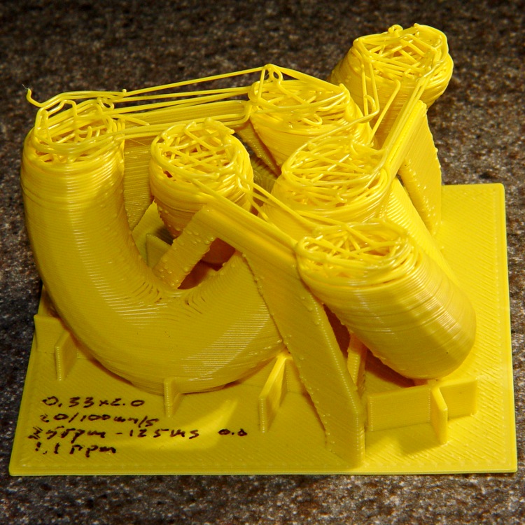
As the scrawled notation says: printed at 50 mm/s with 100 mm/s moves. The only cleanup: remove the scaffolding and slice off the Reversal zittage.
If the truth be known, that was actually the third knot. The first suffered a spectacular failure: one corner of the filament spool snagged on the wall behind the printer and jammed the filament:
Large Knot – failed
The filament drive pulled all the slack out of the bundle, broke off three of the six internal guide posts (admittedly, they’re just hot-melt glued in place), and dragged a nasty kink halfway down the feeder tube. Obviously the stepper was shedding steps during that whole process, but it came rather close to doing the Ouroboros thing.
While that went down, I was puttering around in the far reaches of the Basement Laboratory, attempting to clean up a bit of the clutter, and checking in on the printer every now and again. Seemed like a good idea at the time, is all I can say.
Perhaps the Lords of Cosmic Jest simply decided this was an appropriate object to mess with. The vertices of the hexagonal filament spool stick out perhaps 10 mm from the printer’s backside and every one has cleared the wall on countless previous rotations. I moved the entire affair a bit further from the wall and maybe it’ll be all good from now on.
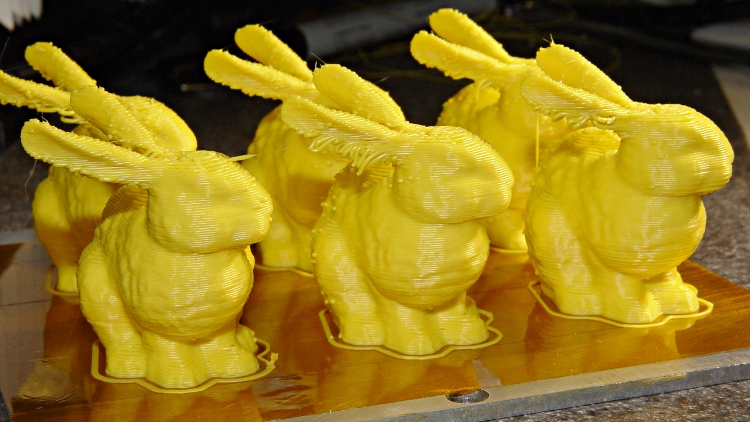
What’s more fun than one Stanford Bunny? A few litters!
These at 50 mm/s feed came out a bit jittery. The ear overhangs were particularly messy:
Small bunnies – ragged edges – 50-100
Another litter at 20 mms/s had better ear overhangs and much smoother coats with less overall jitter:
Small bunnies – ragged ears – 20-100
The obvious shear line across their tummies came from my messing around with the HBP cabling, jerking the X stage while preventing the cables from snagging on the Y stage. Moral of the story: don’t mess around with anything inside the box while it’s printing!
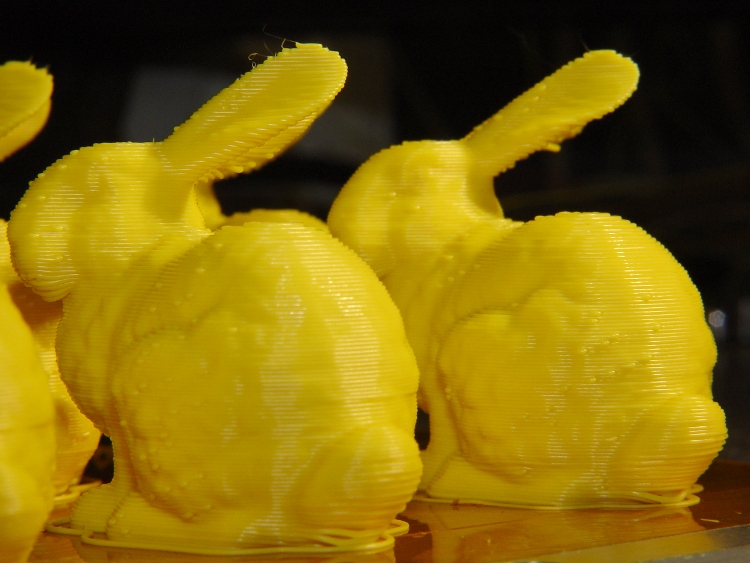
They have little droopy tails:
Small bunnies – droopy tails – 20-100
I think 25 or 30 mm/s would be better all around, as it’d move the extruder away from the Z stage’s mechanical resonance at 1.10 rpm.
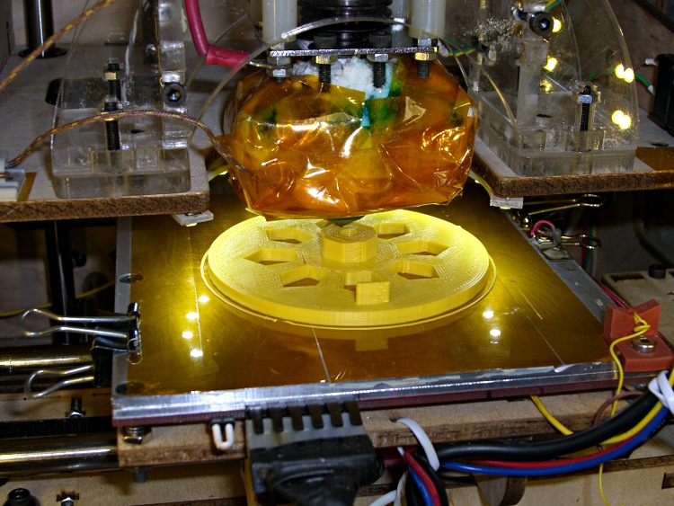
A need for pix of the current waveforms in a stepper motor produced a need to synchronize to the shaft rotation. Rather than cobble something up using random spare parts, I printed a wheel with a tab:
Final rotation sync disk
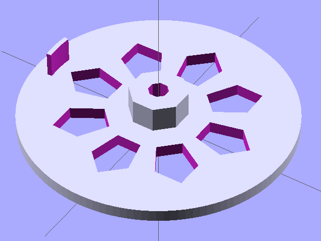
The model looks about like you’d expect:
Synch wheel solid model
Those stretched pentagonal holes give it a vaguely religious aspect, don’t they?
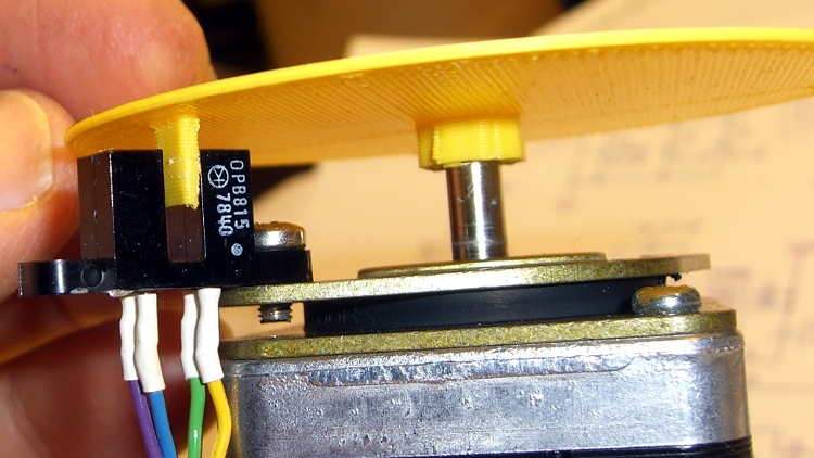
The tab is 2/50 of the circumference, so that the resulting pulse neatly brackets two consecutive groups of four full-step pulses. There’s no way to align the tab with the rotor position, so producing a good scope sync pulse becomes a simple matter of software.
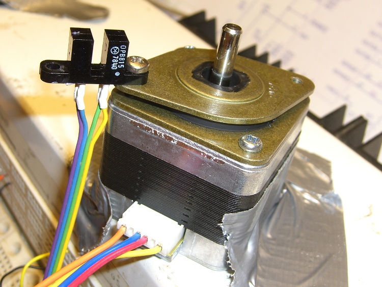
The tab’s length and radial position corresponds to this carefully engineered bit of mayhem:
Optical interrupter on stepper isolator bushing
The shaft hole will be just slightly too small for the motor shaft, which is perfectly fine. Drill the hole to 5 mm using a #9 drill, working your way up from about #12 to keep the hole concentric.
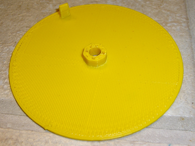
Actually, that was the second version. The first was a quick-and-dirty disk with a tab, but it came out too floppy at only 1 mm thick and utterly boring:
Simple rotation sync disk
But it served as the prototype to settle the tab dimensions and location:
First synch disk with optical interrupter
The OpenSCAD source:
// Optical Interrupter
// Suited for low speed demonstrations!
// Ed Nisley KE4ZNU June 2011

//- Extrusion parameters - must match reality!
//  Print with +2 shells and 3 solid layers

ThreadThick = 0.33;
ThreadWidth = 2.0 * ThreadThick;

//- Plate dimensions

MotorShaftDia = 5.0;
MotorShaftDiaSides = 8;
MotorShaftPolyRadius = (MotorShaftDia/2)/cos(180/MotorShaftDiaSides);

HubDia = MotorShaftDia + 16*ThreadWidth;
HubThick = ceil(10.0/ThreadThick)*ThreadThick;		// total, not added to plate
HubSides = 8;

BladeRadius = 31.5;				// to center of optical switch gap
BladeThick = 2*ThreadWidth;		// measured radially
BladeAngle = (2/50)*360;		// 50 repeats of 4 full step sequences per rev
BladeHeight = 7.0;				// beyond ribs

PlateRadius = BladeRadius + 5.0;
PlateThick = ceil(3.0/ThreadThick) * ThreadThick;

HoleCenterRad = (BladeRadius + HubDia/2)/2;
HoleDia = 0.75 * (3.14159 * 2 * HoleCenterRad)/HubSides;
HoleSides = 5;

//- Convenience items

Protrusion = 0.1;
$fn = 128;						// make large circles very smooth

//- Build it!

difference() {
  union() {
	cylinder(r=PlateRadius,h=PlateThick);			// base plate

	cylinder(r=HubDia/2,h=HubThick,$fn=HubSides);	// hub

	translate([0,0,PlateThick])						// blade
	  difference() {
		cylinder(r=BladeRadius+BladeThick/2,h=BladeHeight);
		cylinder(r=BladeRadius-BladeThick/2,h=BladeHeight + Protrusion);
		rotate([0,0,(180 - BladeAngle/2)])
		  translate([PlateRadius,0,(BladeHeight + Protrusion)/2])
			cube([PlateRadius*2,PlateRadius*2,BladeHeight+Protrusion],center=true);
		rotate([0,0,(BladeAngle/2)])
		  translate([PlateRadius,0,(BladeHeight + Protrusion)/2])
			cube([PlateRadius*2,PlateRadius*2,BladeHeight+Protrusion],center=true);
	  }

  }

  translate([0,0,-Protrusion])						// shaft hole
	cylinder(r=MotorShaftPolyRadius,
			 h=HubThick+2*Protrusion,
			 $fn=MotorShaftDiaSides);

  for (Angle = [0:(HubSides-1)])					// beautification holes
	rotate([0,0,Angle*(360/HubSides)])
	  translate([HoleCenterRad,0,-Protrusion])
		rotate([0,0,180])
		  scale([1.33,1.0,1.0])
			cylinder(r=HoleDia/2,
					 h=(PlateThick + 2*Protrusion),
					 $fn=HoleSides);

}
Yeah, that optical switch really is older than you are…
The reason I didn’t see the yellow low-overheat LED blink on when the Thermal Core ran away was that I’m usually upstairs except when actually printing.
My modus operandi involves sitting at my upstairs desk, fiddling with an OpenSCAD solid model until I like it, then exporting the STL file. This PC has larger screens, better graphics hardware, a fast CPU, a Comfy Chair, and ready access to the kitchen.
The Thing-O-Matic lives in the Basement Laboratory, connected to a dual-core Atom D520 PC running Ubuntu 10.04 LTS with ReplicatorG to control the printer. That PC dual-boots into the RTAI-patched kernel that runs EMC2 for the Sherline mill and is firmly cabled to the Sherline driver box. That PC’s monitor is up on the wall, the chair is a modified lab stool, and the miniature keyboard is barely suited for hunt-and-poke controls. Not a good place to sit and type.
That PC also has a USB webcam showing an interior view of the printer. I run XawTV, a minimal video capture program, to put that view on the PC’s desktop. I could set it up as a webserver camera, but that seems like too much work.
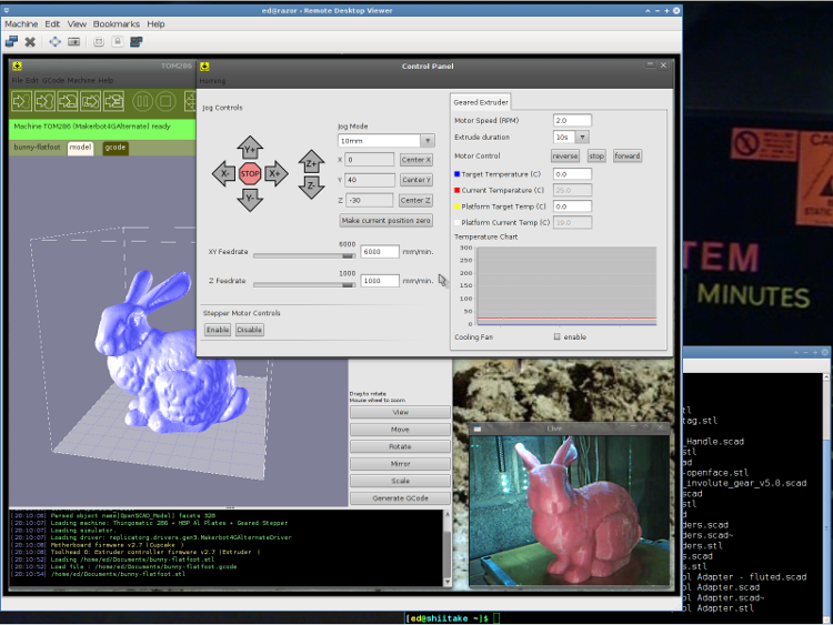
I use the Ubuntu desktop-sharing program to view / control the downstairs programs in a window on my (larger) upstairs monitor, so I can fiddle with RepG from the Comfy Chair. There’s a moderate lag due to stuffing the GUI through the network, but it’s tolerable for small changes & tweaks. The webcam view occupies one corner of the screen.
This is a staged reenactment showing the remote “downstairs” desktop in the left, with the “upstairs” desktop visible to the right:
Remote Desktop Screenshot – lowres
All the files live on our simpleminded server, which sits in the Basement Laboratory’s Computer Wing, and the PCs mount NFS shares from the server. I do all the bulk text editing & file fiddling from the Comfy Chair.
So I save the STL file from the upstairs PC, flip to the window showing the downstairs machine’s desktop, copy the STL to a local drive to avoid lag during operation, run RepG to open the STL and slice it into G-Code, fire the Thing-O-Matic, and trot downstairs to watch the proceedings.
As a rule, I don’t run the printer unattended, but now it looks like it’s a Bad Idea to run the heaters without being nearby. You knew that already, right?
I’d been tweaking an OpenSCAD model, slicing it, not liking the results shown in Skeinlayer, re-tweaking, re-slicing, and iterating around that loop for quite some time. When I figured I was close to having a good model & G-Code, I turned on the heaters to get the printer ready; heating from a cold start requires about 12 minutes due to the double aluminum build plates and hulking cartridge heater adapters.
I made several (well, many) more iterations through OpenSCAD and slicing, flipped to the Control Panel, and discovered the Thermal Core temperature was passing through 285 °C on the way up. Now, the temperature doesn’t rise abruptly, but it was already far higher than the original 210 °C setpoint; you cannot set an Extruder temperature over 260 °C (!) without passing through a confirmation dialog.
Oddly, the setpoint temperatures for both the Extruder and HBP showed 9 °C. The build platform was cooling off, as you would expect for a setpoint far below the actual temperature, but the Thermal Core heater was jammed on.
An LED indicator on the Z stage shows when the EC switches the cartridge heater on. That LED was lit, so I knew the EC had gone nuts: the heater was on, even though the Thermal Core temperature was far above the setpoint.
I passed up an opportunity for Science by punching the Emergency Shutdown button on the Thermal Lockout: the Thing-O-Matic went dark. Turned it back on, reconnected RepG, and ran a few yards of smoking hot filament out of the nozzle. Yes, the Thermal Core really was that hot… I ran the filament drive at 25 rev/min for 10 seconds and it sprayed filament like crazy.
The Thermal Lockout had not tripped, very much as expected. Back when I was figuring out where to mount the thermal switches, those measurements suggested that the Thermal Core would probably exceed 325 °C before the 100 °C NC switch at the top of the Thermal Rise opened. The Core hadn’t gotten close to that temperature, but it was on the way!
The 40 °C NO switch glued to the base of the filament drive had long since closed and lit the yellow LED, but even I agree that’s an absurdly low temperature for such a warning. I have no idea what the actual temperatures were, but I’m thinking of putting a pair of thermocouples in the obvious spots.
I’ve devoted considerable time and energy to eliminating erratic operation and glitchy behavior, to the extent that the printer has behaved flawlessly up to this point. Obviously, something glitched the Extruder Controller, which is basically an Arduino-class microcontroller monitoring two temperature sensors and driving two MOSFETs, while chatting with the Arduino Mega that lives under the Motherboard.
A power glitch will hard-reset the Mega (because I connected +Power Good to -Reset), but the (2.7, anyway) MB firmware has the disturbing property of not resetting the EC when it restarts. You can confirm this by turning the heaters on using the Control Panel, closing it, then blipping the Motherboard Reset button: the heaters remain on. I’ll connect +Power Good to the EC’s -Reset the next time I open the box.
The Thing-O-Matic worked fine (again) after the shutdown, but, as far as I’m concerned, all the effort I put into the Thermal Lockout on the Extruder Heaters has been justified. If the EC ran away once, it will run away again.
I don’t have an MBI MK6+ Thermal Core or their Safety Cutout Switch circuit, but a look at the schematic suggests a heads-up if you use that hardware. The Safety Cutout Switch has (IMO, anyway) several design flaws:
The relay is not energized during normal operation. If it fails to energize when the thermal switch activates, the heater remains active.
By design, the 12 V relay sees only 9 V when the thermal switch operates. The usual wiring resistance and MOSFET resistances, in combination with a sagging power supply, can reduce the available voltage below the relay’s 8.4 V must-operate voltage: it may not cut off the heater.
The relay cannot operate when the ground connection in the Alarm cable isn’t connected, as is the case in a Cupcake without a matching E-Stop jack. In any printer, a disconnected Alarm cable or a broken ground wire will silently prevent the relay from operating.
I’m willing to be proven wrong on any of those points, but as nearly as I can tell, the cartridge heater in a MK6+ can operate with a completely non-functional “Safety Cutout” and you’ll never know there’s a problem. When installed exactly as directed and with the entire printer working properly, it’ll probably work… but if everything worked properly, you wouldn’t need it.
[Update: MBI recently issued a slipstream update that put the Safety Circuit at Rev B. The relay now attaches to the Extruder Controller MOSFET, thus eliminating the requirement for the Alarm cable’s ground. However, the relay now sees the heater’s high-current voltage drop on both terminals. Measure the actual voltage at the Safety Circuit’s input terminals with both heaters running. If that voltage is less than 11.2 V, the relay must operate below its must-operate voltage in order to cut off the Extruder heater.]
The rant at the bottom of that post gave some features that I considered vital when I was designing the Thermal Lockout for my printer. I thought it went without saying that a safety circuit should fail safe: if the safety circuit does not operate, the protected equipment must not operate. As long as the Thermal Switch functions correctly, my Thermal Lockout will fail safe: an inoperative relay, a broken wire, a disconnected switch, or a weak power supply will prevent the printer from starting.
My circuit is not completely fail-safe, of course, but the most common problems cause a hard shutdown.
It really does matter…
I’m now thinking that a thermal switch on the heated build platform is a Good Thing. I suspect the solder will melt and the connector will fall off before melting the acrylic in an ABP or charring the plywood in an HBP, but it’d be interesting to test that assumption, wouldn’t it?