The Smell of Molten Projects in the Morning

Ed Nisley's Blog: Shop notes, electronics, firmware, machinery, 3D printing, laser cuttery, and curiosities. Contents: 100% human thinking, 0% AI slop.

Tag: Thing-O-Matic

Using and tweaking a Makerbot Thing-O-Matic 3D printer

  • NB-5L Holder: Plug Spring Holder

    After that failure, I thought maybe making the spring guide pocket a bit wider and seating the spring wire in a solid plug would work. A tweak to the OpenSCAD script produced this, along with slightly larger locating ribs around the battery compartment:
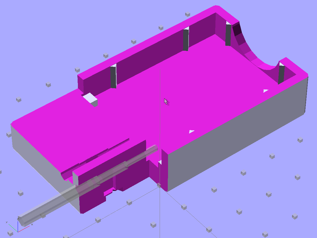
    Plug spring - solid model
    NB-5L Holder – Plug spring – solid model

    A closer look at the plug spring assembly:

    NB-5L Holder - Plug spring - detail
    NB-5L Holder – Plug spring – detail

    The hole is now slightly larger, distinct from the side of the pocket, and the partition between the pocket and plug (although something of a formality) seats the plug during assembly. The plug started out at 3 mm in diameter, as I intended to try ramming a heated wire into a length of filament. That worked, mmmm, somewhat poorly, so I drilled a hole in a length of filament:

    Music wire in filament plug
    Music wire in filament plug

    Unfortunately, that whole bodge didn’t work any better than the spring in the first pass at a holder, so I gave up and cast the springs in epoxy. The OpenSCAD code produces a 5 mm diameter hole that should provide a larger epoxy plate with better grip than the 3 mm holes in this picture, but it probably won’t make much difference:
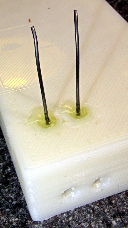
    Music wire in epoxy plug
    Music wire in epoxy plug

    The alert reader will note a complete faceplant: yeah, I forgot to solder the wires into the pins before blobbing the springs in place. Fortunately, the epoxy cures slowly enough that I could:

    • Take the picture
    • Immediately see the obvious problem
    • Ease the music wire springs out just a tidge
    • Extract the pins
    • Quick-like-a-bunny solder wires to pins
    • Insert pins with proper polarity
    • Ease springs back in place

    I hate it when that happens…

    With springs & wires properly in place and the epoxy cured overnight, the pins had considerably better springiness and free motion than before, although they didn’t have quite the range of travel I wanted. I think the spring wire bent slightly on the first push, as the pins never came quite as far out after that.

    So this was a qualified success, but not a solid win. Time for round three…

    The OpenSCAD source code:

    // Holder for Canon NB-5L Li-Ion battery
    // Ed Nisley KE4ZNU August 2011
    
    include </home/ed/Thing-O-Matic/lib/MCAD/units.scad>
    include </home/ed/Thing-O-Matic/lib/MCAD/boxes.scad>
    include </home/ed/Thing-O-Matic/Useful Sizes.scad>
    
    // Layout options
    
    Layout = "Show";					// Case Lid Show Build Fit
    
    //- Extrusion parameters - must match reality!
    //  Print with +2 shells and 3 solid layers
    
    ThreadThick = 0.33;
    ThreadWidth = 2.0 * ThreadThick;
    
    HoleWindage = 0.2;
    
    function IntegerMultiple(Size,Unit) = Unit * ceil(Size / Unit);
    
    Protrusion = 0.1;			// make holes end cleanly
    
    BuildOffset = 3.0;			// clearance for build layout
    
    //- Battery dimensions - rationalized from several samples
    //  Coordinate origin at battery corner by contact plates on bottom surface
    
    BatteryLength = 45.25;
    BatteryWidth = 32.17;
    BatteryThick =  7.85;
    
    ContactWidth = 2.10;
    ContactLength = 4.10;
    ContactRecess = 0.85;
    
    ContactOC = 3.18;			// center-to-center across contact face
    ContactOffset = 4.45;		// offset from battery edge
    ContactHeight = 3.05;		// offset from battery bottom plane
    
    AlignThick = 2.2;			// alignment recesses on contact face
    AlignDepth = 2.0;			// into face
    AlignWidth1 = 0.7;			// across face at contacts
    AlignWidth2 = 2.8;			//  ... other edge
    
    //- Pin dimensions
    
    PinTipDia = 1.6;
    PinTipLength = 10.0;
    
    PinTaperLength = 2.3;
    
    PinShaftDia = 2.4;
    PinShaftLength = 6.8;
    
    PinFerruleDia = 3.0;
    PinFerruleLength = 2.0;
    
    PinLength = PinTipLength + PinTaperLength + PinShaftLength + PinFerruleLength;
    
    PinHoleOffset = 13.9;			// tip to spring hole
    
    ExtendRelax = 1.5 + ContactRecess;		// pin extension when no battery is present
    ExtendOvertravel = 1.0;					//  ... beyond engaged position
    
    //- Holder dimensions
    
    GuideRadius = ThreadWidth;						// friction fit ridges
    GuideOffset = 10;
    WallThick = 4*ThreadWidth;						// holder sidewalls
    
    BaseThick = IntegerMultiple(6.0,ThreadThick);	// bottom of holder to bottom of battery
    TopThick = 6*ThreadThick;	// top of battery to top of holder
    
    ThumbRadius = 10.0;			// thumb opening at end of battery
    
    CornerRadius = 3*ThreadThick;			// nice corner rounding
    
    CaseLength = 2*WallThick + PinLength - ExtendRelax + ExtendOvertravel + BatteryLength + GuideRadius;
    CaseWidth = 2*WallThick + 2*GuideRadius + BatteryWidth;
    CaseThick = BaseThick + BatteryThick + TopThick;
    
    //- XY origin at front left battery corner, Z on platform below that
    
    CaseLengthOffset = -(WallThick + PinLength - ExtendRelax + ExtendOvertravel);
    CaseWidthOffset = -(WallThick + GuideRadius);
    CaseThickOffset = BaseThick;
    
    LidLength = ExtendRelax - CaseLengthOffset;
    
    //- Spring dimensions
    
    SpringPlugDia = 5.0;					// epoxy plug holding spring wire
    SpringPlugLength = IntegerMultiple(1.5,ThreadThick);
    
    SpringDia = 0.024 * inch;	// music wire spring
    SpringTravel = ExtendRelax + ExtendOvertravel;
    SpringLength = BaseThick + ContactHeight - SpringPlugLength - 2*ThreadThick;
    
    echo(str("Spring wire from end: ",WallThick + PinLength - PinHoleOffset));
    echo(str("            from side: ",WallThick + GuideRadius + ContactOffset));
    echo(str("Pin spacing on centers: ",ContactOC));
    
    //----------------------
    // Useful routines
    
    module PolyCyl(Dia,Height,ForceSides=0) {			// based on nophead's polyholes
    
      Sides = (ForceSides != 0) ? ForceSides : (ceil(Dia) + 2);
    
      FixDia = Dia / cos(180/Sides);
    
      cylinder(r=(FixDia + HoleWindage)/2,
               h=Height,
    	   $fn=Sides);
    }
    
    module ShowPegGrid(Space = 10.0,Size = 1.0) {
    
      Range = floor(50 / Space);
    
    	for (x=[-Range:Range])
    	  for (y=[-Range:Range])
    		translate([x*Space,y*Space,Size/2])
    		  %cube(Size,center=true);
    
    }
    
    //-------------------
    
    //-- Guides for tighter friction fit
    
    module Guides() {
      	  translate([GuideOffset,-GuideRadius,CaseThickOffset])
    		PolyCyl(2*GuideRadius,(BatteryThick - Protrusion),4);
    	  translate([GuideOffset,(BatteryWidth + GuideRadius),CaseThickOffset])
    		PolyCyl(2*GuideRadius,(BatteryThick - Protrusion),4);
    	  translate([(BatteryLength - GuideOffset),-GuideRadius,CaseThickOffset])
    		PolyCyl(2*GuideRadius,(BatteryThick - Protrusion),4);
    	  translate([(BatteryLength - GuideOffset),(BatteryWidth + GuideRadius),CaseThickOffset])
    		PolyCyl(2*GuideRadius,(BatteryThick - Protrusion),4);
    	  translate([(BatteryLength + GuideRadius),GuideOffset/2,CaseThickOffset])
    		PolyCyl(2*GuideRadius,(BatteryThick - Protrusion),4);
    	  translate([(BatteryLength + GuideRadius),(BatteryWidth - GuideOffset/2),CaseThickOffset])
    		PolyCyl(2*GuideRadius,(BatteryThick - Protrusion),4);
    
    }
    
    //-- Contact pins (holes therefore)
    
    module PinShape() {
    
    PolyPin = false;
    
      union() {
    	if (PolyPin)
    	  PolyCyl(PinTipDia,(PinTipLength + Protrusion));
    	else
    	  cylinder(r=(PinTipDia + HoleWindage)/2,h=(PinTipLength + Protrusion),$fn=6);
    
    	translate([0,0,PinTipLength])
    	  if (PolyPin)
    		PolyCyl(PinShaftDia,(PinTaperLength + PinShaftLength + Protrusion));
    	  else
    		cylinder(r=(PinShaftDia + HoleWindage)/2,
    				 h=(PinTaperLength + PinShaftLength + Protrusion),$fn=6);
    
    	translate([0,0,(PinLength - PinFerruleLength)])
    	  if (PolyPin)
    		PolyCyl(PinFerruleDia,(PinFerruleLength + Protrusion));
    	  else
    		cylinder(r=(PinFerruleDia + HoleWindage)/2,
    				 h=(PinFerruleLength + Protrusion),$fn=6);
    
    	translate([0,0,PinLength])
    	  if (PolyPin)
    		PolyCyl(PinFerruleDia,PinLength);			// very long holes to punch case
    	  else
    		cylinder(r=(PinFerruleDia + HoleWindage)/2,h=PinLength,$fn=6);
      }
    
    }
    
    module PinAssembly() {
    
      translate([ExtendRelax,ContactOffset,CaseThickOffset + ContactHeight]) {
    	rotate([0,270,0]) {
    	  PinShape();												// pins
    	  translate([0,(2*ContactOC),0])
    		PinShape();
    	}
      }
    
      translate([-(PinHoleOffset - ExtendRelax + SpringTravel/2 - SpringDia/2 - HoleWindage/2),
    			 ContactOffset,
    			 (CaseThickOffset + ContactHeight - SpringLength/2 - Protrusion)]) {
    	  cube([(SpringTravel + SpringDia/2 + HoleWindage),
    		    PinShaftDia,
    			(SpringLength + 2*Protrusion)],
    		   center=true);										// spring deflection pocket
    	  translate([0,(2*ContactOC),0])
    		cube([(SpringTravel + SpringDia/2 + HoleWindage),
    			 PinShaftDia,
    			 (SpringLength + 2*Protrusion)],
    			 center=true);
      }
    
      translate([-(PinHoleOffset - ExtendRelax),
    			 ContactOffset,
    			 (-Protrusion/2)]) {
    	PolyCyl(SpringDia,(BaseThick + ContactHeight + Protrusion),4);		// spring wire
    	PolyCyl(SpringPlugDia,(SpringPlugLength + Protrusion));				// wire holder
    	translate([0,(2*ContactOC),0]) {
    	  PolyCyl(SpringDia,(BaseThick + ContactHeight + Protrusion),4);
    	  PolyCyl(SpringPlugDia,(SpringPlugLength + Protrusion));
    	}
      }
    
    }
    
    //-- Case with origin at battery corner
    
    module Case() {
    
      difference() {
    
    	union() {
    
    	  difference() {
    		translate([(CaseLength/2 + CaseLengthOffset),
    				  (CaseWidth/2 + CaseWidthOffset),
    				  (CaseThick/2)])
    		  roundedBox([CaseLength,CaseWidth,CaseThick],CornerRadius); 	// basic case shape
    
    		translate([-ExtendOvertravel,-GuideRadius,CaseThickOffset])
    		  cube([(BatteryLength + GuideRadius + ExtendOvertravel),
    				(BatteryWidth + 2* GuideRadius),
    				(BatteryThick + Protrusion)]);						// battery space
    
    	  }
    
    	  Guides();
    
    	  translate([-ExtendOvertravel,-GuideRadius,BaseThick])
    		cube([(AlignDepth + ExtendOvertravel),
    			  (AlignWidth1 + GuideRadius),
    			  AlignThick]);											// alignment blocks
    	  translate([-ExtendOvertravel,
    				 (BatteryWidth - AlignWidth2),
    				 BaseThick])
    		cube([(AlignDepth + ExtendOvertravel),
    			  (AlignWidth2 + GuideRadius),
    			  AlignThick]);
    
    	}
    
    	translate([(-ExtendOvertravel),
    			   (CaseWidthOffset - Protrusion),
    			   (CaseThickOffset + BatteryThick)])
    	  cube([CaseLength,
    		    (CaseWidth + 2*Protrusion),
    		    (TopThick + Protrusion)]);								// battery access
    
    	translate([(CaseLengthOffset - Protrusion),
    			   (CaseWidthOffset - Protrusion),
    			   (CaseThickOffset + BatteryThick)])
    	  cube([(CaseLength + 2*Protrusion),
    		    (CaseWidth + 2*Protrusion),
    		    (TopThick + Protrusion)]);								// battery insertion allowance
    
    	translate([(BatteryLength - Protrusion),
    			    (CaseWidth/2 + CaseWidthOffset),
    			    (CaseThickOffset + ThumbRadius)])
    	  rotate([90,0,0])
    		rotate([0,90,0])
    		  cylinder(r=ThumbRadius,
    				   h=(WallThick + GuideRadius + 2*Protrusion),
    				   $fn=22);											// remove thumb notch
    
    	PinAssembly();
    
      }
    
    }
    
    module Lid() {
    
      difference() {
    	translate([0,0,(CaseThick/2 - BaseThick - BatteryThick)])
    	  roundedBox([LidLength,
    				 CaseWidth,CaseThick],CornerRadius);
    
    	translate([0,0,-(CaseThick/2)])
    	  cube([(LidLength + 2*Protrusion),
    		    (CaseWidth + 2*Protrusion),
    		    (CaseThick)],center=true);
      }
    
    }
    
    //-------------------
    // Build it!
    
    ShowPegGrid();
    
    if (Layout == "Case")
      Case();
    
    if (Layout == "Lid")
      Lid();
    
    if (Layout == "Show") {								// reveal pin assembly
      difference() {
    	Case();
    
    	translate([(CaseLengthOffset - Protrusion),
    			   (CaseWidthOffset - Protrusion + WallThick + ContactOffset + ContactOC),
    			   (BaseThick + ContactHeight)])
    	  cube([(-CaseLengthOffset + Protrusion),
    			 (CaseWidth + 2*Protrusion),
    			 CaseThick + BaseThick - ContactHeight + Protrusion]);
    
    	translate([(CaseLengthOffset - Protrusion),
    			   (CaseWidthOffset - Protrusion),
    			   -Protrusion])
    	  cube([(-CaseLengthOffset + Protrusion),
    			 (WallThick + GuideRadius + ContactOffset + Protrusion),
    			 CaseThick]);
      }
    
      translate([ExtendRelax,ContactOffset,CaseThickOffset + ContactHeight]) {	// pins
    	rotate([0,270,0]) {
    	  %PinShape();
    //	  translate([0,(2*ContactOC),0])
    //		%PinShape();
    	}
      }
    
    }
    
    if (Layout == "Build") {
      translate([-(CaseLength/2 + CaseLengthOffset),-(CaseWidthOffset - BuildOffset),0])
    	Case();
      translate([0,(CaseLengthOffset/2 - BuildOffset),0])
    	rotate([0,0,90])
    	  Lid();
    
    }
    
    if (Layout == "Fit") {
      Case();
      translate([(-LidLength/2 + ExtendRelax),
    			(CaseWidth/2 + CaseWidthOffset),
    			(BaseThick + BatteryThick)])
    	  Lid();
      translate([ExtendRelax,ContactOffset,CaseThickOffset + ContactHeight]) {	// pins
    	rotate([0,270,0]) {
    	  %PinShape();
    	  translate([0,(2*ContactOC),0])
    		%PinShape();
    	}
      }
    
    }
    
  • NB-5L Holder: Internal Springs

    The first pass at a holder for a Canon NB-5L battery didn’t quite work, but the failure was instructive. The overall layout was fine; the battery fit well, it’s just that the pins and springs didn’t function properly.

    NB-5L Holder - Internal spring - solid model
    NB-5L Holder – Internal spring – solid model

    I thought a simple straight music wire spring pushed into a hole with a pocket to limit the pin travel would suffice. Watching it build showed that the pocket came out too small and the spring hole was almost completely closed, despite a bit of HoleWindage.

    Here’s a closer look at the spring arrangement, with a pocket at the bottom for an epoxy blob after it became obvious the ABS couldn’t properly anchor the pin.

    NB-5L Holder - Internal spring - detail
    NB-5L Holder – Internal spring – detail

    Drilling out the holes to allow free pin movement ended up with #52 for the tip, #40 for the shaft, and #31 for the ferrule at the end; choose for an easy slip fit.

    I used 0.024 inch (0.6 mm) music wire, which fit neatly into the pin’s inspection hole. Drilling that (#73 drill) into the nearly closed hole through the bottom showed that things weren’t working well: far too much resistance along what should be a half-open channel.

    With the pin in place and a stub of wire pushed upward into the pin, the pins moved very stiffly and tended to not return to their rest position. Minus the spring wire, they slid freely.

    After a bit of this and that, I tried 0.020 music wire, which didn’t have enough return force at all.

    The end of the spring wire moved around a lot more than I think it should have, gradually turning the hole into an oval. I drilled two pockets in the bottom (and changed the solid model to match what you see above) and cast a dab of epoxy into each hole; that solved the moving-around problem, but the pins were still too stiff.

    NB-5L Holder - first version - bottom
    NB-5L Holder – first version – bottom

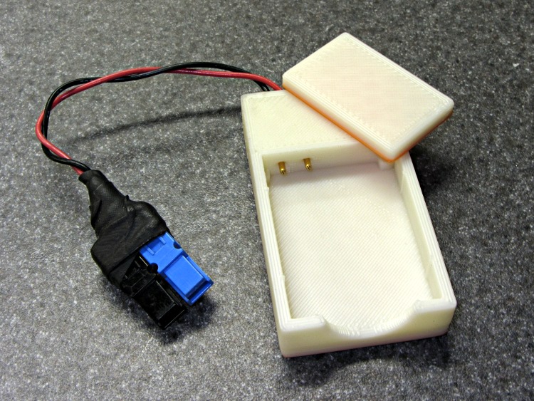
    The weird orange color comes from a few layers of Safety Orange filament that melded into white in mid-flight. No reason to use fancy filament on a prototype, methinks; that’s what was in place when I started.

    But I glued the cap on anyway to see if the pins would work well enough to run some early battery tests. This is what it looked like before gluing the cap:

    NB-5L Holder - first version
    NB-5L Holder – first version

    The Powerpole connectors came from one of those packs, with the wires soldered into the ends of the pins so as to not block the inspection holes that I’m using for the music wire springs.

    The OpenSCAD source code:

    // Holder for Canon NB-5L Li-Ion battery
    // Ed Nisley KE4ZNU August 2011
    
    include </home/ed/Thing-O-Matic/lib/MCAD/units.scad>
    include </home/ed/Thing-O-Matic/lib/MCAD/boxes.scad>
    include </home/ed/Thing-O-Matic/Useful Sizes.scad>
    
    // Layout options
    
    Layout = "Show";					// Case Lid Show Build Fit
    
    //- Extrusion parameters - must match reality!
    //  Print with +2 shells and 3 solid layers
    
    ThreadThick = 0.33;
    ThreadWidth = 2.0 * ThreadThick;
    
    HoleWindage = 0.2;
    
    function IntegerMultiple(Size,Unit) = Unit * ceil(Size / Unit);
    
    Protrusion = 0.1;			// make holes end cleanly
    
    BuildOffset = 3.0;			// clearance for build layout
    
    //- Battery dimensions - rationalized from several samples
    //  Coordinate origin at battery corner by contact plates on bottom surface
    
    BatteryLength = 45.25;
    BatteryWidth = 32.17;
    BatteryThick =  7.85;
    
    ContactWidth = 2.10;
    ContactLength = 4.10;
    ContactRecess = 0.85;
    
    ContactOC = 3.18;			// center-to-center across contact face
    ContactOffset = 4.45;		// offset from battery edge
    ContactHeight = 3.05;		// offset from battery bottom plane
    
    AlignThick = 2.2;			// alignment recesses on contact face
    AlignDepth = 2.0;			// into face
    AlignWidth1 = 0.7;			// across face at contacts
    AlignWidth2 = 2.8;			//  ... other edge
    
    //- Pin dimensions
    
    PinTipDia = 1.6;
    PinTipLength = 10.0;
    
    PinTaperLength = 2.3;
    
    PinShaftDia = 2.4;
    PinShaftLength = 6.8;
    
    PinFerruleDia = 3.0;
    PinFerruleLength = 2.0;
    
    PinLength = PinTipLength + PinTaperLength + PinShaftLength + PinFerruleLength;
    
    PinHoleOffset = 13.9;			// tip to spring hole
    
    //- Spring dimensions
    
    ExtendRelax = 1.5 + ContactRecess;		// pin extension when no battery is present
    ExtendOvertravel = 1.0;					//  ... beyond engaged position
    
    SpringDia = 0.024 * inch;	// music wire spring
    SpringTravel = ExtendRelax + ExtendOvertravel;
    SpringLength = 4.0 + PinShaftDia/2;			// free length below pin centerline
    
    //- Holder dimensions
    
    GuideRadius = ThreadWidth;						// friction fit ridges
    GuideOffset = 10;
    WallThick = 4*ThreadWidth;						// holder sidewalls
    
    BaseThick = IntegerMultiple(6.0,ThreadThick);	// bottom of holder to bottom of battery
    TopThick = 6*ThreadThick;	// top of battery to top of holder
    
    ThumbRadius = 10.0;			// thumb opening at end of battery
    
    CornerRadius = 3*ThreadThick;			// nice corner rounding
    
    CaseLength = 2*WallThick + PinLength - ExtendRelax + ExtendOvertravel + BatteryLength + GuideRadius;
    CaseWidth = 2*WallThick + 2*GuideRadius + BatteryWidth;
    CaseThick = BaseThick + BatteryThick + TopThick;
    
    //- XY origin at front left battery corner, Z on platform below that
    
    CaseLengthOffset = -(WallThick + PinLength - ExtendRelax + ExtendOvertravel);
    CaseWidthOffset = -(WallThick + GuideRadius);
    CaseThickOffset = BaseThick;
    
    LidLength = ExtendRelax - CaseLengthOffset;
    
    SpringPlugDia = 3.0;			// filament snippet holding spring wire
    SpringPlugLength = IntegerMultiple(1.0,ThreadThick);
    
    echo(str("Spring wire from end: ",WallThick + PinLength - PinHoleOffset));
    echo(str("            from side: ",WallThick + GuideRadius + ContactOffset));
    echo(str("Pin spacing on centers: ",ContactOC));
    
    //----------------------
    // Useful routines
    
    module PolyCyl(Dia,Height,ForceSides=0) {			// based on nophead's polyholes
    
      Sides = (ForceSides != 0) ? ForceSides : (ceil(Dia) + 2);
    
      FixDia = Dia / cos(180/Sides);
    
      cylinder(r=(FixDia + HoleWindage)/2,
               h=Height,
    	   $fn=Sides);
    }
    
    module ShowPegGrid(Space = 10.0,Size = 1.0) {
    
      Range = floor(50 / Space);
    
    	for (x=[-Range:Range])
    	  for (y=[-Range:Range])
    		translate([x*Space,y*Space,Size/2])
    		  %cube(Size,center=true);
    
    }
    
    //-------------------
    
    //-- Guides for tighter friction fit
    
    module Guides() {
      	  translate([GuideOffset,-GuideRadius,CaseThickOffset])
    		PolyCyl(2*GuideRadius,(BatteryThick - Protrusion),4);
    	  translate([GuideOffset,(BatteryWidth + GuideRadius),CaseThickOffset])
    		PolyCyl(2*GuideRadius,(BatteryThick - Protrusion),4);
    	  translate([(BatteryLength - GuideOffset),-GuideRadius,CaseThickOffset])
    		PolyCyl(2*GuideRadius,(BatteryThick - Protrusion),4);
    	  translate([(BatteryLength - GuideOffset),(BatteryWidth + GuideRadius),CaseThickOffset])
    		PolyCyl(2*GuideRadius,(BatteryThick - Protrusion),4);
    	  translate([(BatteryLength + GuideRadius),GuideOffset/2,CaseThickOffset])
    		PolyCyl(2*GuideRadius,(BatteryThick - Protrusion),4);
    	  translate([(BatteryLength + GuideRadius),(BatteryWidth - GuideOffset/2),CaseThickOffset])
    		PolyCyl(2*GuideRadius,(BatteryThick - Protrusion),4);
    
    }
    
    //-- Contact pins (holes therefore)
    
    module PinShape() {
    
    PolyPin = false;
    
      union() {
    	if (PolyPin)
    	  PolyCyl(PinTipDia,(PinTipLength + Protrusion));
    	else
    	  cylinder(r=(PinTipDia + HoleWindage)/2,h=(PinTipLength + Protrusion),$fn=6);
    
    	translate([0,0,PinTipLength])
    	  if (PolyPin)
    		PolyCyl(PinShaftDia,(PinTaperLength + PinShaftLength + Protrusion));
    	  else
    		cylinder(r=(PinShaftDia + HoleWindage)/2,
    				 h=(PinTaperLength + PinShaftLength + Protrusion),$fn=6);
    
    	translate([0,0,(PinLength - PinFerruleLength)])
    	  if (PolyPin)
    		PolyCyl(PinFerruleDia,(PinFerruleLength + Protrusion));
    	  else
    		cylinder(r=(PinFerruleDia + HoleWindage)/2,
    				 h=(PinFerruleLength + Protrusion),$fn=6);
    
    	translate([0,0,PinLength])
    	  if (PolyPin)
    		PolyCyl(PinFerruleDia,PinLength);			// very long holes to punch case
    	  else
    		cylinder(r=(PinFerruleDia + HoleWindage)/2,h=PinLength,$fn=6);
      }
    
    }
    
    module PinAssembly() {
    
      translate([ExtendRelax,ContactOffset,CaseThickOffset + ContactHeight]) {	// pins
    	rotate([0,270,0]) {
    	  PinShape();
    	  translate([0,(2*ContactOC),0])
    		PinShape();
    	}
      }
    
      translate([-(PinHoleOffset - ExtendRelax + SpringTravel/2),
    			 ContactOffset,
    			 (CaseThickOffset + ContactHeight - SpringLength/2 + Protrusion/2)]) {
    	  cube([SpringTravel,
    		    (2*SpringDia),
    			(SpringLength + Protrusion)],
    		   center=true);										// spring deflection pocket
    	  translate([0,(2*ContactOC),0])
    		cube([SpringTravel,
    			 (2*SpringDia),
    			 (SpringLength + Protrusion)],
    			 center=true);
      }
    
      translate([-(PinHoleOffset - ExtendRelax),
    			 ContactOffset,
    			 (-Protrusion/2)]) {
    	PolyCyl(SpringDia,(BaseThick + ContactHeight + Protrusion));		// spring wire
    	PolyCyl(SpringPlugDia,(SpringPlugLength + Protrusion));				// wire holder
    	translate([0,(2*ContactOC),0]) {
    	  PolyCyl(SpringDia,(BaseThick + ContactHeight + Protrusion));
    	  PolyCyl(SpringPlugDia,(SpringPlugLength + Protrusion));
    	}
      }
    
    }
    
    //-- Case with origin at battery corner
    
    module Case() {
    
      difference() {
    
    	union() {
    
    	  difference() {
    		translate([(CaseLength/2 + CaseLengthOffset),
    				  (CaseWidth/2 + CaseWidthOffset),
    				  (CaseThick/2)])
    		  roundedBox([CaseLength,CaseWidth,CaseThick],CornerRadius); 	// basic case shape
    
    		translate([-ExtendOvertravel,-GuideRadius,CaseThickOffset])
    		  cube([(BatteryLength + GuideRadius + ExtendOvertravel),
    				(BatteryWidth + 2* GuideRadius),
    				(BatteryThick + Protrusion)]);						// battery space
    
    	  }
    
    	  Guides();
    
    	  translate([-ExtendOvertravel,-GuideRadius,BaseThick])
    		cube([(AlignDepth + ExtendOvertravel),
    			  (AlignWidth1 + GuideRadius),
    			  AlignThick]);											// alignment blocks
    	  translate([-ExtendOvertravel,
    				 (BatteryWidth - AlignWidth2),
    				 BaseThick])
    		cube([(AlignDepth + ExtendOvertravel),
    			  (AlignWidth2 + GuideRadius),
    			  AlignThick]);
    
    	}
    
    	translate([(-ExtendOvertravel),
    			   (CaseWidthOffset - Protrusion),
    			   (CaseThickOffset + BatteryThick)])
    	  cube([CaseLength,
    		    (CaseWidth + 2*Protrusion),
    		    (TopThick + Protrusion)]);								// battery access
    
    	translate([(CaseLengthOffset - Protrusion),
    			   (CaseWidthOffset - Protrusion),
    			   (CaseThickOffset + BatteryThick)])
    	  cube([(CaseLength + 2*Protrusion),
    		    (CaseWidth + 2*Protrusion),
    		    (TopThick + Protrusion)]);								// battery insertion allowance
    
    	translate([(BatteryLength - Protrusion),
    			    (CaseWidth/2 + CaseWidthOffset),
    			    (CaseThickOffset + ThumbRadius)])
    	  rotate([90,0,0])
    		rotate([0,90,0])
    		  cylinder(r=ThumbRadius,
    				   h=(WallThick + GuideRadius + 2*Protrusion),
    				   $fn=22);											// remove thumb notch
    
    	PinAssembly();
    
      }
    
    }
    
    module Lid() {
    
      difference() {
    	translate([0,0,(CaseThick/2 - BaseThick - BatteryThick)])
    	  roundedBox([LidLength,
    				 CaseWidth,CaseThick],CornerRadius);
    
    	translate([0,0,-(CaseThick/2)])
    	  cube([(LidLength + 2*Protrusion),
    		    (CaseWidth + 2*Protrusion),
    		    (CaseThick)],center=true);
      }
    
    }
    
    //-------------------
    // Build it!
    
    ShowPegGrid();
    
    if (Layout == "Case")
      Case();
    
    if (Layout == "Lid")
      Lid();
    
    if (Layout == "Show") {								// reveal pin assembly
      difference() {
    	Case();
    
    	translate([(CaseLengthOffset - Protrusion),
    			   (CaseWidthOffset - Protrusion + WallThick + ContactOffset + ContactOC),
    			   (BaseThick + ContactHeight)])
    	  cube([(-CaseLengthOffset + Protrusion),
    			 (CaseWidth + 2*Protrusion),
    			 CaseThick + BaseThick - ContactHeight + Protrusion]);
    
    	translate([(CaseLengthOffset - Protrusion),
    			   (CaseWidthOffset - Protrusion),
    			   -Protrusion])
    	  cube([(-CaseLengthOffset + Protrusion),
    			 (WallThick + GuideRadius + ContactOffset + Protrusion),
    			 CaseThick]);
      }
    
      translate([ExtendRelax,ContactOffset,CaseThickOffset + ContactHeight]) {	// pins
    	rotate([0,270,0]) {
    	  %PinShape();
    //	  translate([0,(2*ContactOC),0])
    //		%PinShape();
    	}
      }
    
    }
    
    if (Layout == "Build") {
      translate([-(CaseLength/2 + CaseLengthOffset),-(CaseWidthOffset - BuildOffset),0])
    	Case();
      translate([0,(CaseLengthOffset/2 - BuildOffset),0])
    	rotate([0,0,90])
    	  Lid();
    
    }
    
    if (Layout == "Fit") {
      Case();
      translate([(-LidLength/2 + ExtendRelax),
    			(CaseWidth/2 + CaseWidthOffset),
    			(BaseThick + BatteryThick)])
    	  Lid();
      translate([ExtendRelax,ContactOffset,CaseThickOffset + ContactHeight]) {	// pins
    	rotate([0,270,0]) {
    	  %PinShape();
    	  translate([0,(2*ContactOC),0])
    		%PinShape();
    	}
      }
    
    }
    
  • Toy Dump Truck Convoy

    Dump Truck fleet
    Dump Truck fleet

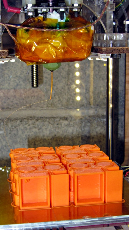
    The Tiny Toy Dump Truck by madscifi makes a fine tchotchke for a presentation, serving to illustrate the risks and rewards of printing flat overhangs without support. A fleet of six printed well, after repairing some failures as those tall, tall rings and posts near the dump bed pivot fell over. I pasted them down in mid-print using ABS slurry, which is not a technique to emulate.

    A closer look shows the overhang problem in the dump bed and the broken pillars behind the wheels.

    Truck overhang failure - grayscale
    Truck overhang failure – grayscale

    It’s in monochrome because the camera choked on that much Safety Orange filament in the image, to the extent that no amount of color correction produced a usable result.

  • Canon NB-5L Battery Holder Doodles

    A first cut at a holder for Canon NB-5L batteries with those dimensions, with the intent of connecting them to a battery tester.

    NB-5L Battery Holder Doodle
    NB-5L Battery Holder Doodle

    The cloud in the middle of the bottom holds pin dimensions, which I measured after I’d been doodling for a bit. They come from my heap; they’re nice heavy-gold plated male pins (yeah, I have the other gender, too) intended for a multi-pin connector. They have a convenient hole that’s normally used to verify you’ve actually soldered the wire properly. I plan to stick a music-wire spring in the hole and secure it through the bottom of the holder with a rectangular pocket below the pin that limits the travel in both directions. Drilling the hole completely through the pin to let the spring wire stick out would prevent having it fall out at the end of travel.

    The spring pocket dimensions are right down around the very limit of the feature sizes my TOM can achieve. I’m not sure those blind holes will actually open up far enough.

    I’m also not sure the Powerpoles will actually fit in there like that. There’s nothing wrong with pigtail leads.

    It’s obviously styled after the Official Canon NB-5L charger, although they use nice bent-steel spring contacts that are trivially easy to make in mass production:

    Canon NB-5L charger
    Canon NB-5L charger
  • Tux Cookie Cutter

    Sean asked me to conjure up a Tux cookie cutter for the presentation on DIY 3D Printing and the Makerbot Thing-O-Matic I’m doing at the Mid-Hudson Valley LUG meeting tonight and, as is always the case, it took a bit more conjuring than either of us expected.

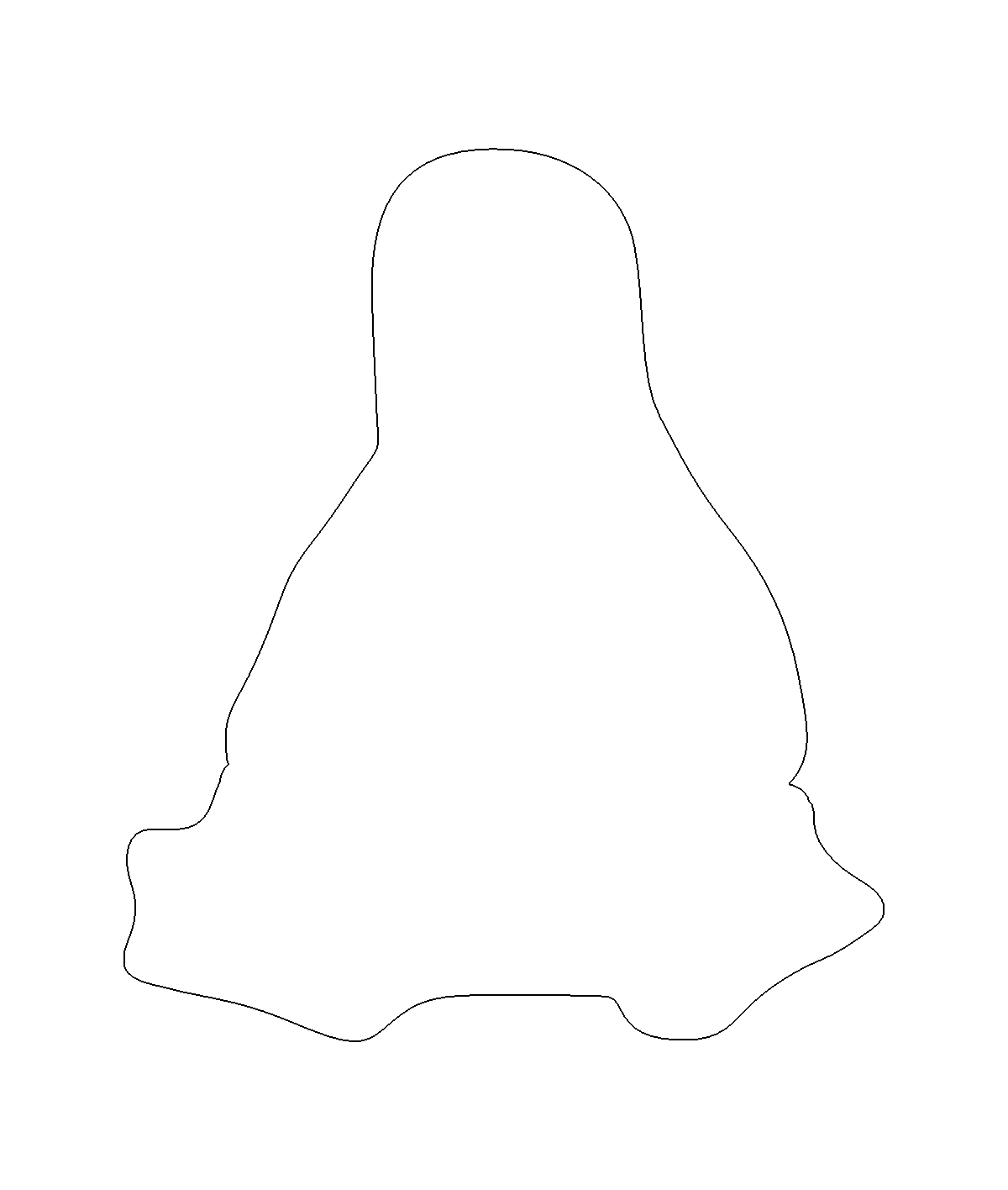
    For Tux pix, one should start with Larry Ewing’s drawings; I used the EPS version to get a scalable vector drawing. Run it through The GIMP, close the outline at the flippers, fill with black, save as PNG. Then import into Inkscape, trace the outline, and something like this pops out:

    Tux Outline
    Tux Outline

    The reason for using Inkscape is that OpenSCAD imports a very limited subset of all possible DXF files and, while Inkscape can (with some care) produce a DXF format that OpenSCAD can import, somehow the shape lacked interior fill. Sean took a slightly different approach with the same tools and managed to create a useful DXF file that produced this chunk o’ bits:

    Tux Slab - solid model
    Tux Slab – solid model

    The DXF import still didn’t work dependably, so I exported the Tux Slab from OpenSCAD to an STL file; if you want to extrude a solid Tux, that’s probably the way to go. Importing the STL in the next steps worked fine.

    The Parametric Cookie Cutter by nateoostendorp creates thin cutter walls by subtracting a linear dimension from the X- and Y-axis extents of the shape. Unfortunately, Tux has crazy flipper feet that didn’t respond well to that; the walls developed gaps at the inflection points from self-intersections.

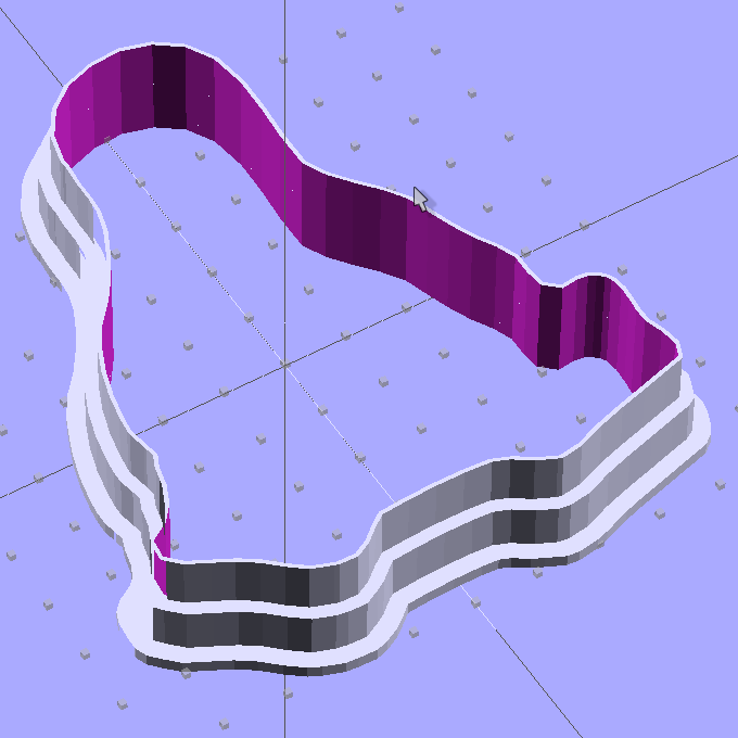
    So I started from scratch with a Minkowski sum, which in this case amounts to rubbing a cylinder all over the Tux shape, then intersecting the resulting mega-penguin-post with a slab of the appropriate thickness sitting on the Z=0 plane. The Minkowski enlarges the XY outline by the cylinder’s radius and the Z thickness by twice the cylinder’s height, which I picked to be grossly excessive. Three Minkowskis produce the lip, wall, and tip of the cutter, which then stack up with a Tux-shaped hole subtracted from their midst:

    Tux Cookie Cutter - solid model
    Tux Cookie Cutter – solid model

    The thicknesses and heights all derive directly from the extrusion parameters used to print the thing, because there’s not much room for roundoff. The middle section (the wall) is four threads wide, but Skeinforge divides the interior pair of threads into shorter sections with breakpoints at each sharp corner. The cutter section (the lip) is one thread wide, because I couldn’t get a good result with two threads.

    The OpenSCAD preview has trouble with the Minkowski result and produces weird rendering glitches, but the CGAL model comes through fine. Note that Tux now has the opposite chirality, a gross oversight that became obvious only after the third cutter emerged from the Basement Laboratory. Here’s the second cutter:

    Tux Cutter - reversed
    Tux Cutter – reversed

    Each cutter takes about 35 minutes to build, so I boiled the highlights down into a thrilling 6 minute movie.

    The OpenSCAD source code, into which you can substitute your very own STL shape file:

    // Tux cookie cutter using Minkowski sum
    // Ed Nisley KE4ZNU - Sept 2011
    
    //- Extrusion parameters - must match reality!
    
    ThreadThick = 0.33;
    ThreadWidth = 2.0 * ThreadThick;
    
    function IntegerMultiple(Size,Unit) = Unit * ceil(Size / Unit);
    
    MaxSize = 110;				// larger than any possible dimension ...
    
    //- Cookie cutter parameters
    
    Size = 100;
    
    TipHeight = IntegerMultiple(8,ThreadThick);
    TipThick = 1*ThreadWidth;
    
    WallHeight = IntegerMultiple(7,ThreadThick);
    WallThick = 4*ThreadWidth;
    
    LipHeight = IntegerMultiple(1.5,ThreadWidth);
    LipThick = IntegerMultiple(5,ThreadWidth);
    
    //- Wrapper for the shape of your choice
    
    module Shape(Size) {
      Tux(Size);
    }
    
    //- A solid slab of Tux goodness in simple STL format
    // Choose magic values to:
    //		center it in XY
    //		reversed across Y axis (prints with handle on bottom)
    //		bottom on Z=0
    //		make it MaxSize from head to feet
    
    module Tux(Scale) {
      STLscale = 250;
      scale(Scale/STLscale)
    	translate([105,-145,0])
    	  scale([-1,1,24])
    		import_stl(
    		  file = "/mnt/bulkdata/Project Files/Thing-O-Matic/Tux Cookie Cutter/Tux Plate.stl",
    		  convexity=5);
    }
    
    //- Given a Shape(), return enlarged slab of given thickness
    
    module EnlargeSlab(Scale, WallThick, SlabThick) {
    
    	intersection() {
    	  translate([0,0,SlabThick/2])
    		cube([MaxSize,MaxSize,SlabThick],center=true);
    	  minkowski() {
    		Shape(Scale);
    		cylinder(r=WallThick,h=MaxSize);
    	  }
    	}
    
    }
    
    //- Put peg grid on build surface
    
    module ShowPegGrid(Space = 10.0,Size = 1.0) {
    
      Range = floor(50 / Space);
    
    	for (x=[-Range:Range])
    	  for (y=[-Range:Range])
    		translate([x*Space,y*Space,Size/2])
    		  %cube(Size,center=true);
    
    }
    
    //- Build it
    
    ShowPegGrid();
    
    //cube(5);
    
    difference() {
      union() {
    	translate([0,0,(WallHeight + LipHeight)])
    	  EnlargeSlab(Size,TipThick,TipHeight);
    	translate([0,0,LipHeight])
    	  EnlargeSlab(Size,WallThick,WallHeight);
    	EnlargeSlab(Size,LipThick,LipHeight);
      }
      Shape(Size);					// punch out cookie hole
    }
    
  • Stepper Dynamometer: Sync Wheel

    This is a modification of that sync gadget to work on the prototype stepper dynamometer. The key differences:

    • The wheel has a notch rather than a flag
    • The opto switch mounts on a sturdy post

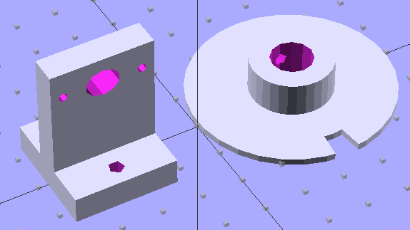
    The wheel fits the shaft with a 4-40 setscrew to hold it in place. The post has 4-40 mounting holes for one of those optical switches, plus a big hole for the wiring. The solid models look about like you’d expect:

    Wheel and post solid model
    Wheel and post solid model

    I located the post’s holes on the baseplate with a spindly pair of transfer punches, after transferring the wheel’s centerline by eyeballometric guesstimation:

    Locating holes with transfer punches
    Locating holes with transfer punches

    Then aligned the baseplate on the Sherline, located the holes, and drilled ’em with manual CNC to get the proper spacing:

    Drilling opto switch post holes
    Drilling opto switch post holes

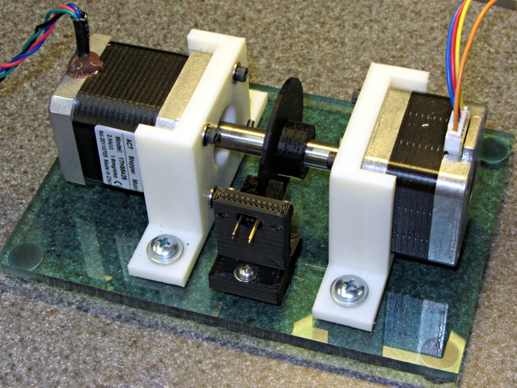
    And then it went together quite smoothly:

    Dyno with sync wheel
    Dyno with sync wheel

    What’s really nice about 3D printing is you can build stuff like this without too much fuss & bother: figure out the solid model, walk gingerly through the software minefield, and (usually) assemble the parts later that day.

    A bit of wiring to power the LED and pull up the phototransistor should do the trick.

    The OpenSCAD code, including a few tweaks that rationalize spacings and sizes and suchlike:

    // Optical Interrupter for stepper dynamometer
    // Suited for low speed demonstrations!
    // Ed Nisley KE4ZNU August 2011
    
    include </home/ed/Thing-O-Matic/lib/MCAD/units.scad>
    include </home/ed/Thing-O-Matic/Useful Sizes.scad>
    
    // Layout options
    
    Layout = "Build";					// Build Show Wheel Switch
    
    //- Extrusion parameters - must match reality!
    //  Print with +2 shells and 3 solid layers
    
    ThreadThick = 0.33;
    ThreadWidth = 2.0 * ThreadThick;
    
    HoleWindage = 0.3;
    
    function IntegerMultiple(Size,Unit) = Unit * ceil(Size / Unit);
    
    Protrusion = 0.1;
    
    //- Wheel dimensions
    
    ShaftDia = (3/8) * inch;
    ShaftHeight = 27.39;					// from motor mount assembly
    
    HubDia = IntegerMultiple(ShaftDia,ThreadWidth) + 15*ThreadWidth;
    HubLength = IntegerMultiple(10.0,ThreadThick);		// total, not added to plate
    
    SetScrewOffset = 2*Tap4_40;
    SetScrewDia = Tap4_40;
    
    WheelRadius = IntegerMultiple(24.0,ThreadWidth);
    WheelThick = IntegerMultiple(1.5,ThreadThick);
    
    CutoutAngle = (2/50)*360;
    CutoutWidth = WheelRadius*tan(CutoutAngle);
    CutoutDepth = 6.0;
    
    echo(str("Wheel radius: ",WheelRadius," dia: ",2*WheelRadius," thick: ",WheelThick));
    echo(str("Hub sidewall:",(HubDia - ShaftDia)/2));
    echo(str("Cutout width: ",CutoutWidth," angle: ",CutoutAngle," depth: ",CutoutDepth));
    
    //- Optical switch dimensions
    
    OSBaseLength = (31/32) * inch;
    OSBaseWidth = (1/4) * inch;
    OSBaseThick = 0.100 * inch;
    
    OSLeadSpace = 0.300 * inch;							// leads fit though this opening
    
    OSHolesOC = (3/4) * inch;							// switch mounting holes
    OSHoleDia = Tap4_40;
    
    SwHeight = IntegerMultiple((ShaftHeight + OSBaseWidth),ThreadThick);
    SwWidth = IntegerMultiple(OSBaseLength,ThreadWidth);
    SwThick = IntegerMultiple(OSBaseWidth,ThreadWidth);
    
    SwBaseWidth = 4*SwThick;							// pillar base width
    SwBaseOC = IntegerMultiple(2.5*SwThick,1.0);		// base screw spacing
    
    echo(str("Pillar height: ",SwHeight," width: ",SwWidth," thick: ",SwThick));
    echo(str("       base screws: ",SwBaseOC," OC"));
    
    //----------------------
    // Useful routines
    
    module PolyCyl(Dia,Height,ForceSides=0) {			// based on nophead's polyholes
    
      Sides = (ForceSides != 0) ? ForceSides : (ceil(Dia) + 2);
    
      FixDia = Dia / cos(180/Sides);
    
      cylinder(r=(FixDia + HoleWindage)/2,
               h=Height,
    	   $fn=Sides);
    }
    
    module ShowPegGrid(Space = 10.0,Size = 1.0) {
    
      Range = floor(50 / Space);
    
    	for (x=[-Range:Range])
    	  for (y=[-Range:Range])
    		translate([x*Space,y*Space,Size/2])
    		  %cube(Size,center=true);
    
    }
    
    module Sector(OutR,InR,Thick,Angle) {
    
      difference() {
    	cylinder(r=OutR,h=Thick);
    	cylinder(r=InR,h=Thick);
    
    	rotate([0,0,CutoutAngle/2])
    	  translate([0,OutR,Thick/2])
    		cube([OutR*2,OutR*2,Thick],center=true);
    	rotate([0,0,-CutoutAngle/2])
    	  translate([0,-OutR,Thick/2])
    		cube([OutR*2,OutR*2,Thick],center=true);
      }
    }
    
    //-- Interrupter Wheel
    
    module Wheel() {
    
      difference() {
    	union() {
    	  cylinder(r=WheelRadius,h=WheelThick);			// base plate
    	  cylinder(r=HubDia/2,h=HubLength);				// hub
    	}
    
    	translate([0,0,-Protrusion])						// shaft hole
    	  PolyCyl(ShaftDia,(HubLength + 2*Protrusion));
    
    	translate([0,0,(HubLength - SetScrewOffset)])
    	  rotate([0,270,0])
    		PolyCyl(SetScrewDia,HubDia);
    
    	translate([0,0,-Protrusion])						// sector cutout
    	  Sector((WheelRadius + Protrusion),
    			(WheelRadius - CutoutDepth),
    			(WheelThick + 2*Protrusion),
    			CutoutAngle);
      }
    
    }
    
    //-- Optical Switch Mount
    
    module SwitchMount() {
    
      difference() {
    	union() {											// mounting pillar
    	  translate([0,0,SwHeight/2])
    		cube([SwThick,SwWidth,SwHeight],center=true);
    	  translate([0,0,SwThick/2])
    		cube([SwBaseWidth,SwWidth,SwThick],center=true);
    	}
    
    	translate([0,0,ShaftHeight]) {
    	  translate([-(SwThick/2 + Protrusion),0,0])		// lead clearance slot
    		rotate([0,90,0])
    		  scale([(OSBaseWidth/OSLeadSpace),1,1])
    			PolyCyl(OSLeadSpace,(SwThick + 2*Protrusion));
    
    	  for (y=[-1,1])									// switch screws
    		translate([0,(y*OSHolesOC/2),0])
    		  rotate([0,90,0])
    			cylinder(r=Tap4_40/2,h=(SwThick + 2*Protrusion),center=true,$fn=6);
    	}
    
    	for (x=[-1,1])										// base screws
    	  translate([(x*SwBaseOC/2),0,-Protrusion])
    		rotate([0,0,(x-1)*90])							// get points outward
    		  PolyCyl(Clear4_40,(SwThick + 2*Protrusion));
      }
    
    }
    
    //-------------------
    // Build it!
    
    ShowPegGrid();
    
    if (Layout == "Build") {
      translate([0,WheelRadius,0])
    	Wheel();
      translate([0,-SwWidth,0])
    	SwitchMount();
    }
    
    if (Layout == "Wheel")
      Wheel();
    
    if (Layout == "Switch")
      SwitchMount();
    
    if (Layout == "Show") {
      translate([0,WheelThick/2,ShaftHeight])
    	rotate([90,0,0])
    	  Wheel();
      translate([(WheelRadius + OSBaseThick + SwThick/2),0,0])
    	SwitchMount();
    }
    

    The sizes differ slightly from the photos, but you’d never see the difference.

  • OpenSCAD vs. Skeinforge 40: Bogus G-Code

    My first pass at the NEMA 17 motor mount bracket used additive modeling, glomming together several blocks made from cube primitives:

    • The motor mounting plate, less five holes
    • Two side struts to stiffen the motor plate
    • The baseplate, minus two mounting holes

    Makes perfect sense to me; perhaps I’m an additive kind of guy. That produced an OpenSCAD model with positive surfaces for the various parts and negative surfaces inside the holes:

    NEMA 17 Mount - additive model
    NEMA 17 Mount – additive model

    Compile that through CGAL, export as STL, inhale into RepG 25, and you (well, I) get what looks to be a fine object in the preview pane:

    NEMA 17 RepG preview - additive
    NEMA 17 RepG preview – additive

    Then run it through Skeinforge 40, which emits a flurry of messages along these lines:

    [19:11:08] Warning, the triangle mesh slice intersects itself in getLoopsFromCorrectMesh in triangle_mesh.
    [19:11:08] Something will still be printed, but there is no guarantee that it will be the correct shape.
    [19:11:08] Once the gcode is saved, you should check over the layer with a z of:
    [19:11:09] 0.165
    

    The usual searching suggested that sometimes Skeinforge has problems with coincident surfaces, such as between the motor mount plate and the struts and the base, or coincident edges where two blocks abut. Judging from the messages, the problem ran all the way to the top of the struts. Oddly, Skeinview didn’t show any problems, so the G-Code was (presumably) OK.

    Error messages tend to make me twitchy, though. I modified the OpenSCAD code to extend the struts 0.1 mm inside the base and ran that model through the software stack, which produced not a single complaint about anything, anywhere.

    Success!

    However, painful experience has caused me to review the G-Code for every single object with the Skeinlayer plugin, which, right on cue, revealed this interesting anomaly:

    NEMA 17 Mount - Skeinview - Bad gcode
    NEMA 17 Mount – Skeinview – Bad gcode

    That happened for every layer in the square motor mount plate: the lower right corner is fine, the upper left seems to be the negative of the actual solid model. The holes are filled, the plate is empty. The Skirt outline ignores the smaller holes, goes around the large one, and continues on its merry way.

    I putzed around for a while and discovered that the failure seems acutely sensitive to the side strut thickness. Yeah, like that makes any sense.

    Any variations along those lines that I tried generated either:

    • A flurry of mesh error messages, with seemingly good G-Code
    • No error messages whatsoever, with totally bogus G-Code

    Running the STL files through netfabb Cloud Service produced the same diagnostic for both:

    Number of holes: 3
    Number of shells: 2
    Mesh is not manifold and oriented.
     We unfortunately have not yet enough experience with the occuring server loads, that we can securely enable shell merging at the moment.
    

    However, the repaired STL files produce correct G-Code: evidently OpenSCAD spits out bogus STL data. The fact that RepG/SF treats the two files differently suggests improved diagnostics would be in order, but that’s in the nature of fine tuning.

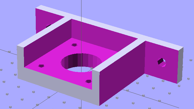
    So I junked the additive model and went subtractive, chewing the recesses out of one huge block:

    NEMA 17 Stepper Mount - solid model
    NEMA 17 Stepper Mount – solid model

    That worked:

    Number of holes: 0
    Number of shells: 1
    Mesh is manifold and oriented.
    

    I like processes that don’t emit error messages or result in mysterious failures, although it’s not obvious that subtractive modeling will always produce correct results. Heck, I’m not sure I can think in terms of negative volumes all that well.

    The OpenSCAD code for the additive model, with a highlight on the conditional that will trigger the two errors:

    // NEMA 17 stepper motor mount
    // Ed Nisley KE4ZNU August 2011
    
    include </home/ed/Thing-O-Matic/lib/MCAD/units.scad>
    
    //-- Layout Control
    
    Layout = "Build";				// Build Show None
    
    Examine = "None";				// Mount Stand None
    
    //-- Extrusion parameters
    
    ThreadThick = 0.33;
    ThreadWT = 2.0;
    ThreadWidth = ThreadThick * ThreadWT;
    
    HoleWindage = 0.3;			// enlarge hole dia by this amount
    
    function IntegerMultiple(Size,Unit) = Unit * ceil(Size / Unit);
    
    //-- Useful sizes
    
    Tap2_56 = 0.070 * inch;
    Clear2_56 = 0.082 * inch;
    Head2_56 = 0.156 * inch;
    Head2_56Thick = 0.055 * inch;
    Nut2_56Dia = 0.204 * inch;
    Nut2_56Thick = 0.065 * inch;
    
    Tap3_48 = 0.079 * inch;
    Clear3_48 = 0.096 * inch;
    Head3_48 = 0.184 * inch;
    Head3_48Thick = 0.058 * inch;
    Nut3_48Dia = 0.201 * inch;
    Nut3_48Thick = 0.073 * inch;
    
    Tap4_40 = 0.089 * inch;
    Clear4_40 = 0.110 * inch;
    Head4_40 = 0.211 * inch;
    Head4_40Thick = 0.065 * inch;
    Nut4_40Dia = 0.228 * inch;
    Nut4_40Thick = 0.086 * inch;
    
    Tap10_32 = 0.159 * inch;
    Clear10_32 = 0.190 * inch;
    Head10_32 = 0.373 * inch;
    Head10_32Thick = 0.110 * inch;
    Nut10_32Dia = 0.433 * inch;
    Nut10_32Thick = 0.130 * inch;
    
    NEMA17_ShaftDia = 5.0;
    NEMA17_ShaftLength = 24.0;
    NEMA17_PilotDia = 0.866 * inch;
    NEMA17_PilotLength = 0.080 * inch;
    NEMA17_BCD = 1.725 * inch;
    NEMA17_BoltDia = 3.5;
    NEMA17_BoltOC = 1.220 * inch;
    
    //-- Mount Sizes
    
    MountSide = IntegerMultiple(NEMA17_BCD,ThreadWidth);
    MountThick = IntegerMultiple(8.0,ThreadThick);
    
    MountBoltDia = 3.0;
    
    StrutThick = IntegerMultiple(5.0,ThreadWidth);
    StrutHeight = MountSide;
    
    StandThick = IntegerMultiple(4.0,ThreadWidth);
    
    UprightLength = IntegerMultiple(MountSide + 2*StrutThick,5);
    
    StandBoltAllowance = IntegerMultiple(Head10_32,5);
    StandBoltOC = UprightLength + 2*StandBoltAllowance;
    
    StandLength = IntegerMultiple(StandBoltOC + 2*StandBoltAllowance,ThreadWidth);
    StandWidth = IntegerMultiple(2*StandBoltAllowance,ThreadThick);
    
    echo(str("Stand Base: ",StandLength," x ",StandWidth));
    echo(str("Stand Bolt OC: ",StandBoltOC));
    
    //-- Convenience values
    
    Protrusion = 0.1;		// make holes look good and joints intersect properly
    
    BuildOffset = 3 * ThreadWidth;
    
    //----------------------
    // Useful routines
    
    module PolyCyl(Dia,Height,ForceSides=0) {			// based on nophead's polyholes
    
      Sides = (ForceSides != 0) ? ForceSides : (ceil(Dia) + 2);
    
      FixDia = Dia / cos(180/Sides);
    
      cylinder(r=(FixDia + HoleWindage)/2,
               h=Height,
    	   $fn=Sides);
    }
    
    module ShowPegGrid(Space = 10.0,Size = 1.0) {
    
      Range = floor(50 / Space);
    
    	for (x=[-Range:Range])
    	  for (y=[-Range:Range])
    		translate([x*Space,y*Space,Size/2])
    		  %cube(Size,center=true);
    
    }
    
    //----------------------
    // Motor Mount plate
    
    module MotorMount() {
    
      difference() {
    	translate([0,0,MountThick/2])
    	  cube([MountSide,MountSide,MountThick],center=true);
    if (true) {
    	translate([0,0,-Protrusion])
    	  PolyCyl(NEMA17_PilotDia,(MountThick + 2*Protrusion));
    }
    else {
    	translate([0,0,MountThick - NEMA17_PilotLength])
    	  PolyCyl(NEMA17_PilotDia,(NEMA17_PilotLength + Protrusion));
    	translate([0,0,-Protrusion])
    	  PolyCyl(1.5*NEMA17_ShaftDia,(MountThick + 2*Protrusion));
    }
    	for (x=[-1,1])
    	  for (y=[-1,1])
    		translate([x*NEMA17_BoltOC/2,y*NEMA17_BoltOC/2,-Protrusion])
    		  PolyCyl(MountBoltDia,(MountThick + 2*Protrusion));
      }
    
    }
    
    //----------------------
    // Stand to support the plate
    
    module Stand() {
    
      difference() {
    
    	union() {
    	  translate([0,0,StandThick/2])
    		cube([StandLength,StandWidth,StandThick],center=true);
    	  for (x=[-1,1])						// side support struts
    if (true)	// this causes bizarre negative rendering and a diagonal negative section
    		translate([(x*((MountSide + StrutThick)/2)),0,
    				  (StandThick + StrutHeight/2 - Protrusion/2)])
    		  cube([StrutThick,StandWidth,(StrutHeight + Protrusion)],center=true);
    else	// this generates "triangle slice mesh intersects iself"
    		translate([(x*((MountSide + StrutThick)/2)),0,
    				  (StandThick + StrutHeight/2)])
    		  cube([StrutThick,StandWidth,StrutHeight],center=true);
    	}
    
    	for (x=[-1,1])
    	  translate([x*StandBoltOC/2,0,-Protrusion])
    		PolyCyl(Clear10_32,StandThick + 2*Protrusion);
      }
    }
    
    //----------------------
    // Combined for single build
    
    module Combined() {
    
    //  union() {
    	translate([-MountSide/2,0,0])
    	  MotorMount();
    
    	translate([StandThick,0,StandWidth/2])
    	  rotate([90,0,270])
    		Stand();
    
    //  }
    }
    
    //----------------------
    // Lash everything together
    
    ShowPegGrid();
    
    if (Examine == "Mount")
      MotorMount();
    
    if (Examine == "Stand")
      Stand();
    
    if (Layout == "Build" && Examine == "None") {
      translate([MountSide/2,0,0])
    	Combined();
    }
    
    if ((Layout == "Show") && Examine == "None") {
      translate([-StandWidth/2,0,StandThick])
    	rotate([0,90,0])
    	  Combined();
    }
    

    OpenSCAD depends on CGAL for all the 3D heavy lifting, which puts any STL export problems further upstream.  I suppose I could open Yet Another RepG ticket to get better diagnostics, but the others haven’t gotten much attention so far and I suppose it’s not really their problem anyway.