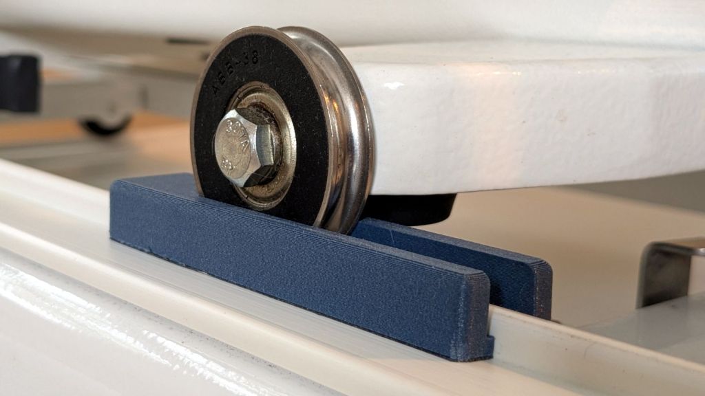
Trying out the Track Lock Blocks brought a long-standing puzzle to the surface: the left front wheel rode about a millimeter above its track, with the other three wheels carrying the weight of the machine. Neither that wheel nor the diagonally opposite wheel on the right rear worked well with the Blocks, because the machine rocked on the other two wheels.
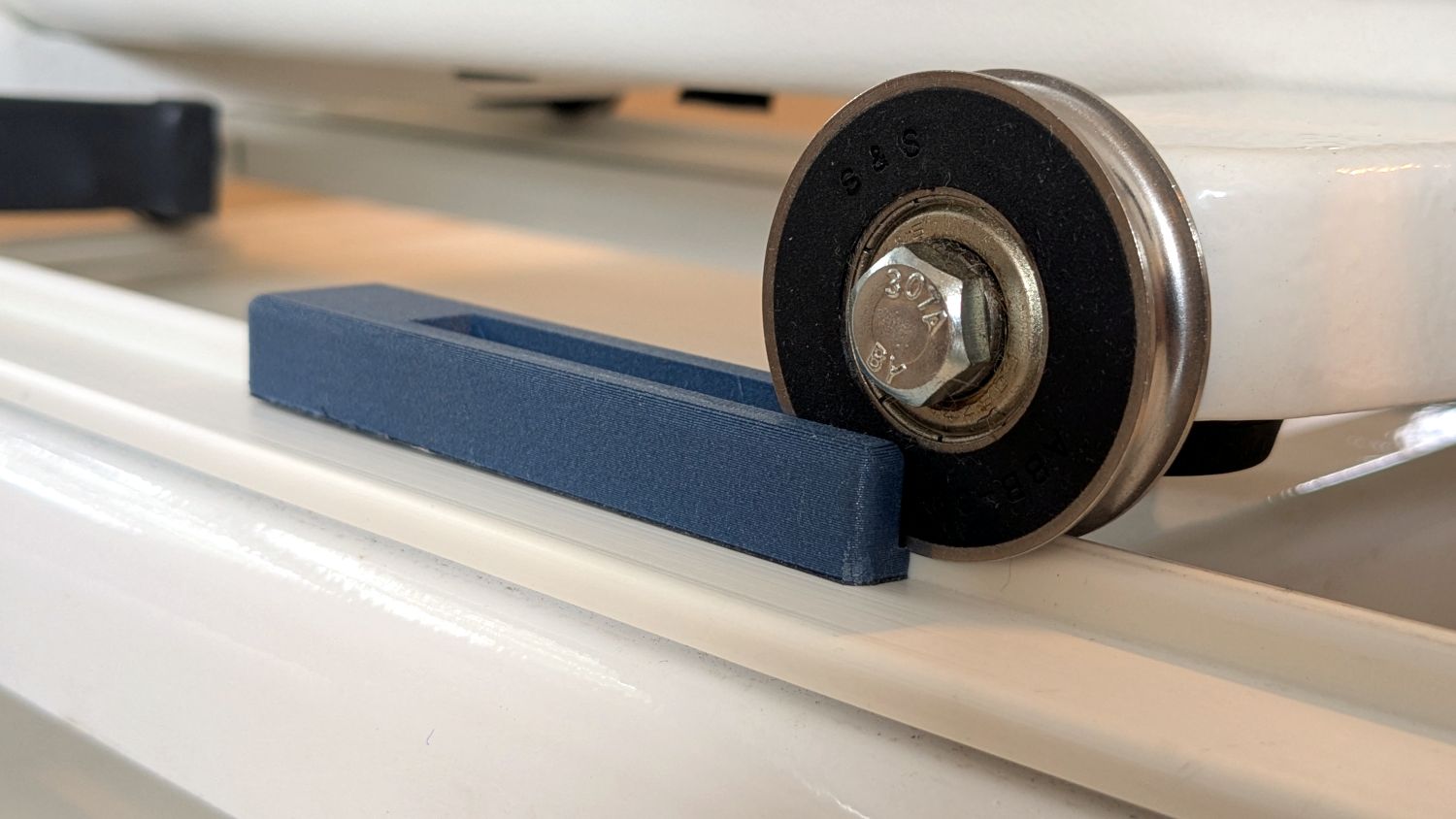
I initially thought the carriage rail under the machine was warped, but some poking and prodding showed the left front wheel rode higher than the others from front to back across the entire length of the table.
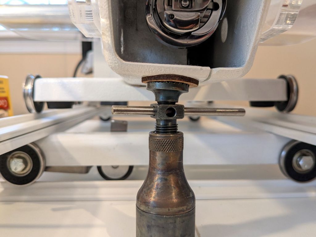
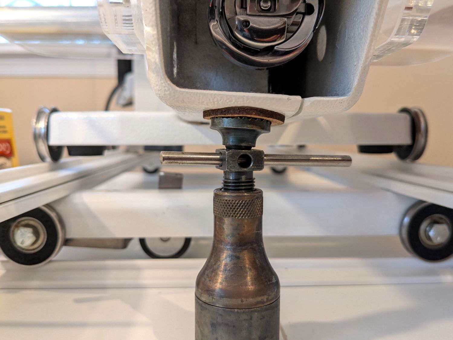
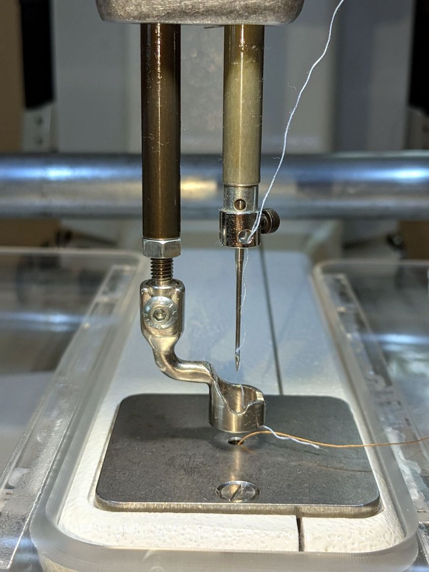
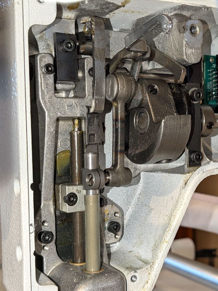
So I loosened the screws holding the front wheel base plate to the machine and jacked up the front of the machine to get the wheels off their tracks:
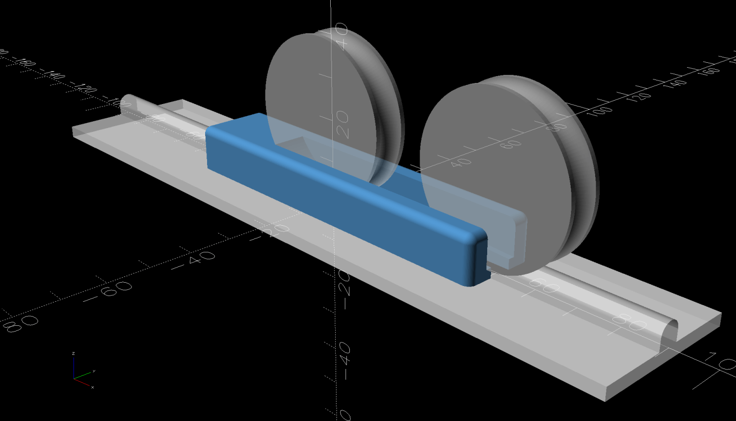
Then I jammed two strips of chipboard into the left side of the gap:
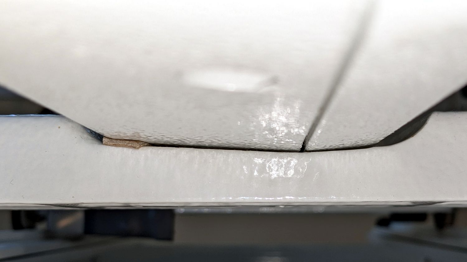
I planned to use one long strip across the entire wheel base plate, but the screw holding the machine casting to the plate blocks the way, so it now has two shorter strips. Tightening the screws clamped the chipboard in place.
The chipboard tilted the base plate and lowered the left wheel, with the right wheel surely moving slightly upward. Lowering the machine showed both front wheels now carry roughly the same load and the Track Lock Blocks now work the way I expected.
After doing that, I found the recommended procedure in the official HQ Sixteen Service and Troubleshooting manual:
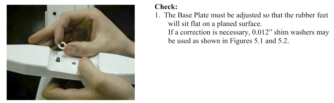
The only “planed surface” around here is on the surface plate in the Basement Shop, two flights of stairs away, and I am not carrying either object to meet the other.
In any event, I think the chipboard serves the same purpose as a simple washer, with advantage of a much larger bearing surface, so I’ll call it Good Enough until something else causes me to take the wheel base plate off.


