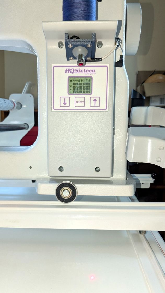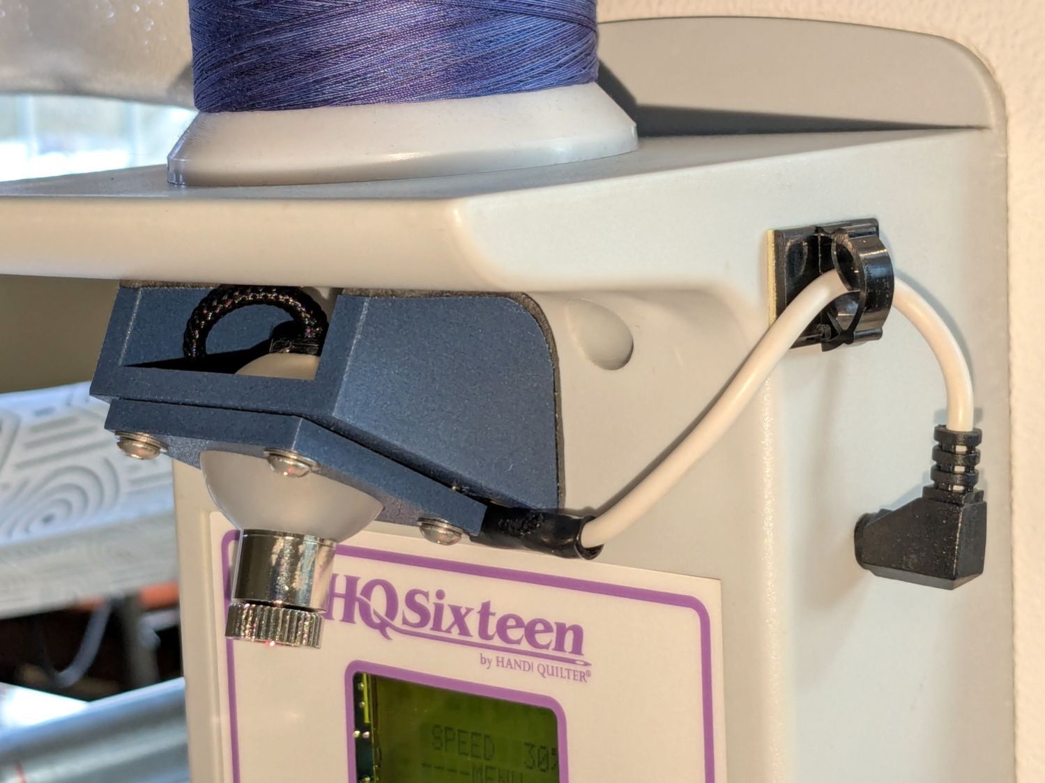
Having devoted considerable effort to smoothing the HQ Sixteen’s path across the table, with commensurate improvement, Mary reported the machine suddenly developed a severe hitch in its left-to-right git-along. Given that she is moving fifty pounds of machine with fingertip pressure, anything interrupting its progress is a problem.
We found a spot where the machine abruptly and repeatably stopped rolling, but none of the four wheels had a visible problem and both tracks were smooth. The stitch regulator wheel sat directly above a table surface joint on the track base, but lifting it didn’t change the glitch. Rolling the machine while lifting the rear wheels off the track, which is significantly more difficult than it may seem, still encountered the bump.
Rolling while lifting the front wheels went smoothly, so something was wrong with one of the front wheels. I put the machine back at the worst spot, marked the bottom of both wheel rims, lifted-and-rotated the left wheel half a turn, and found the glitch happened with the right wheel’s mark downward.
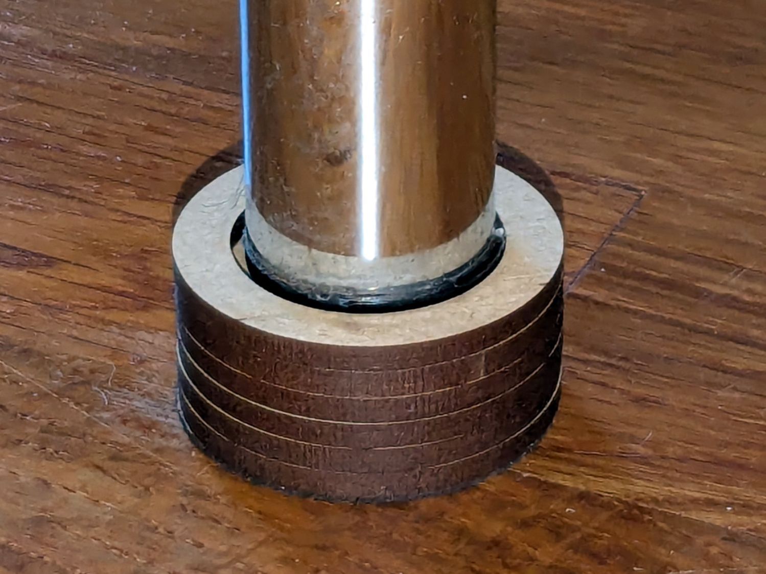
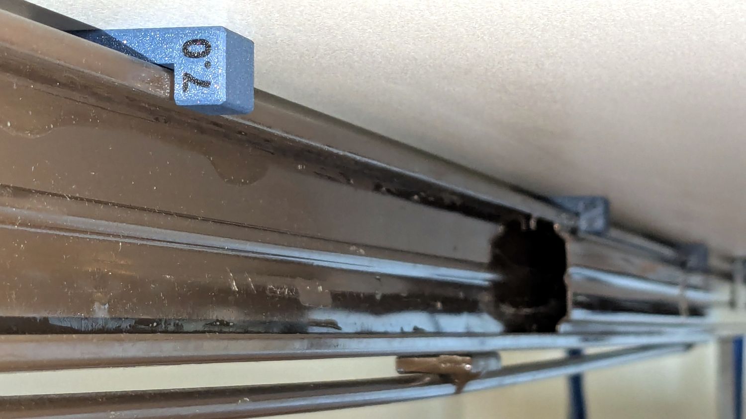
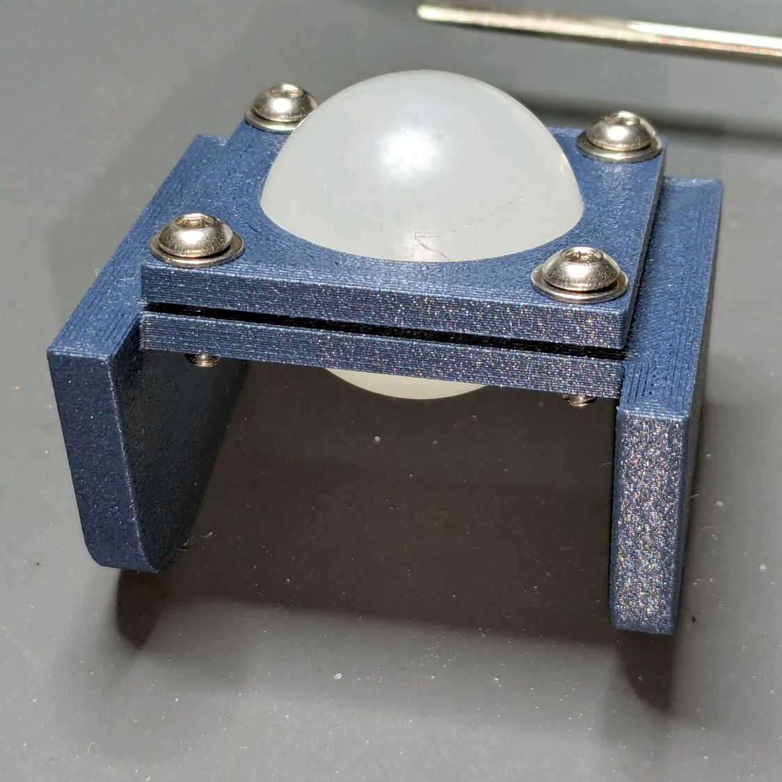
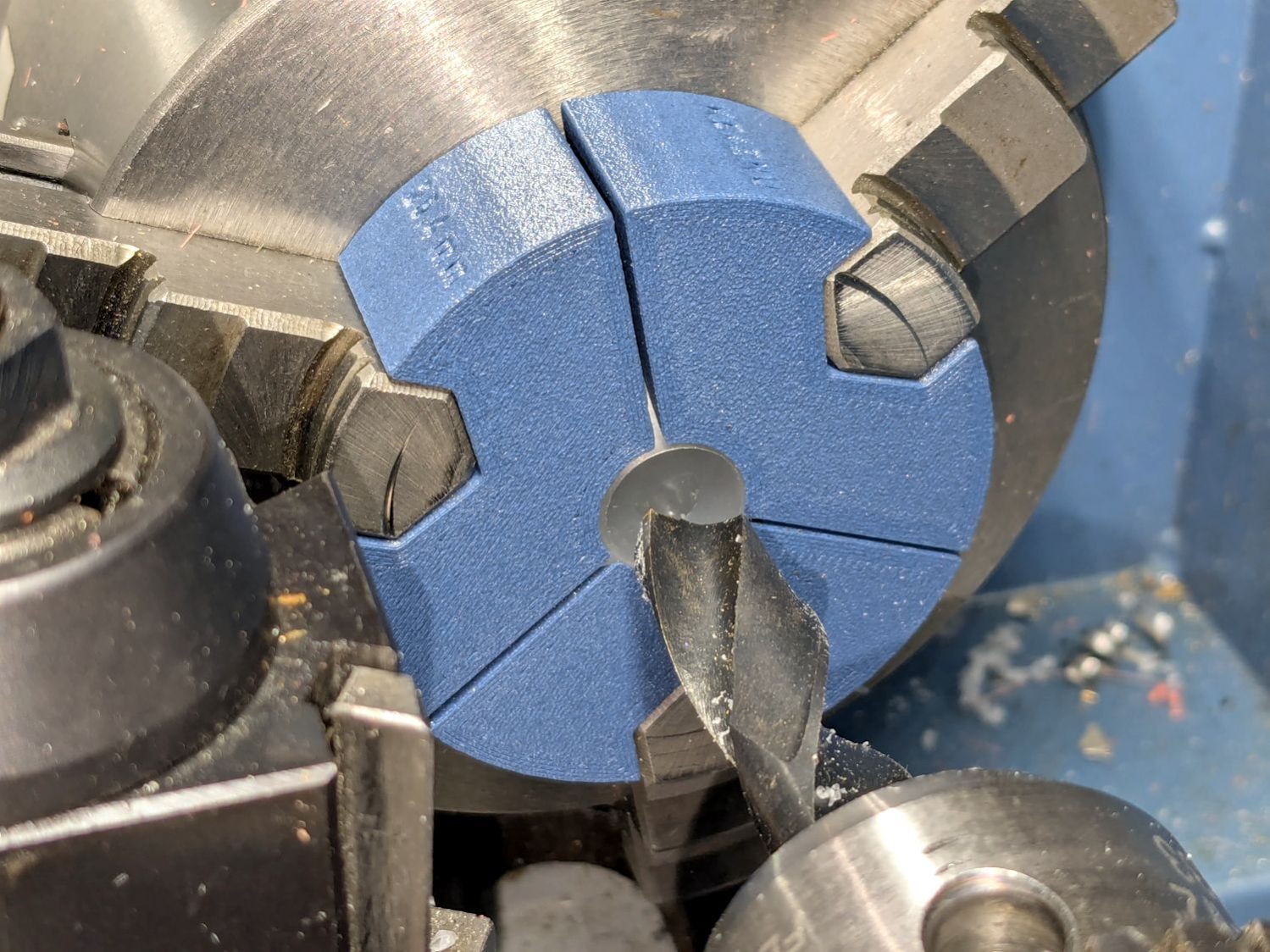
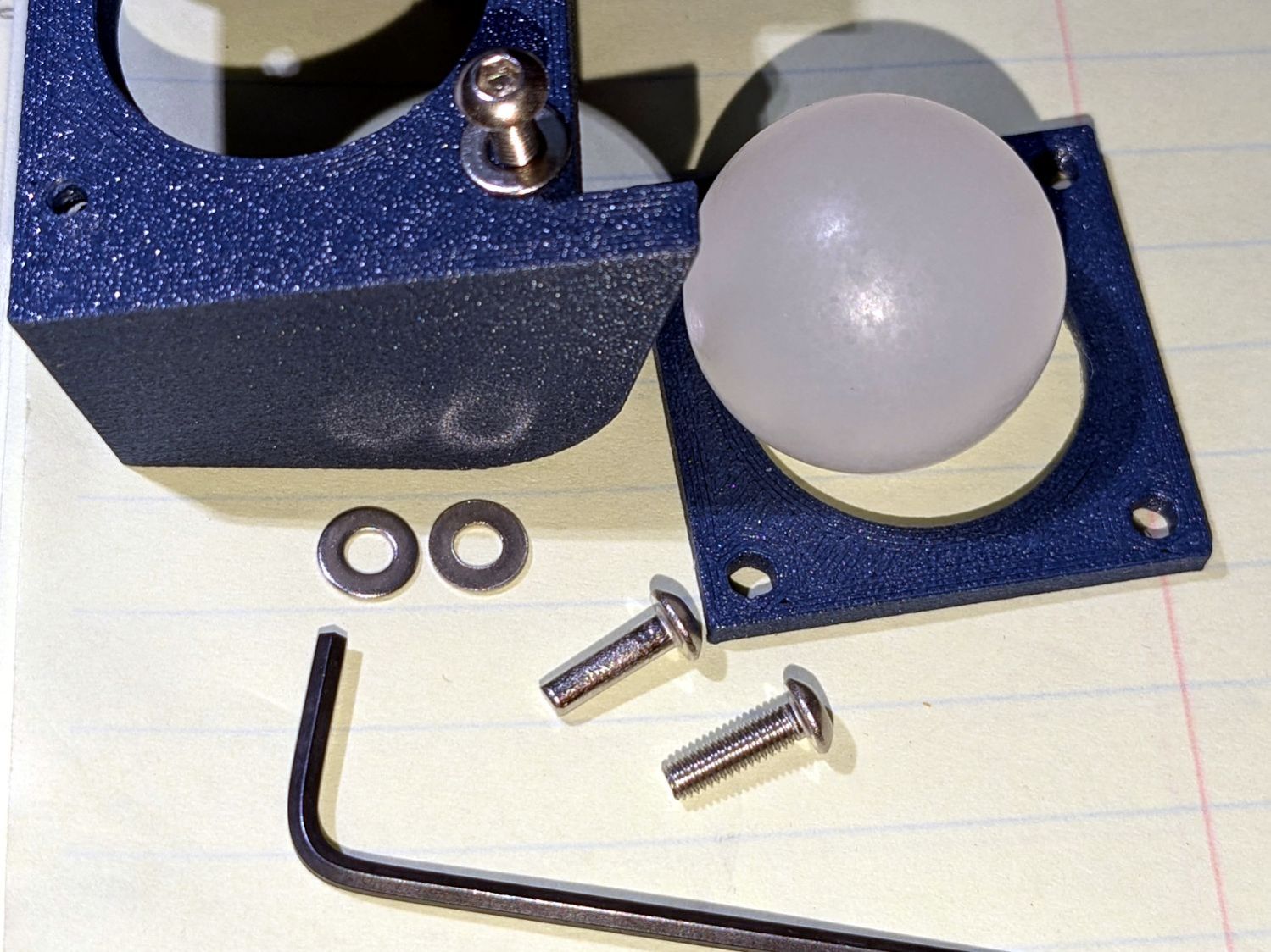
I lifted the machine off the carriage, took the carriage to the Basement Shop, and discovered what we could not see in situ:
For scale, the wheels are 8 mm across the flanges.
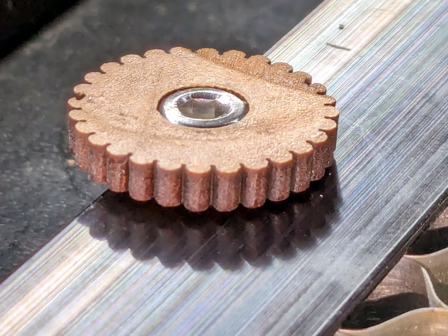
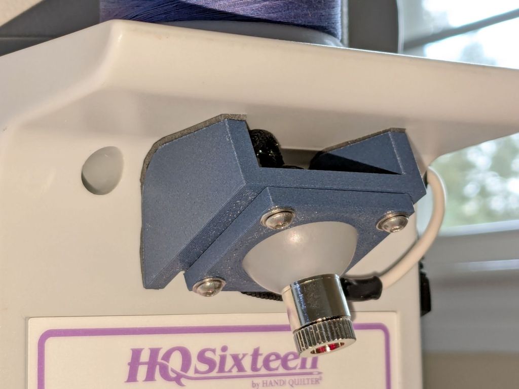
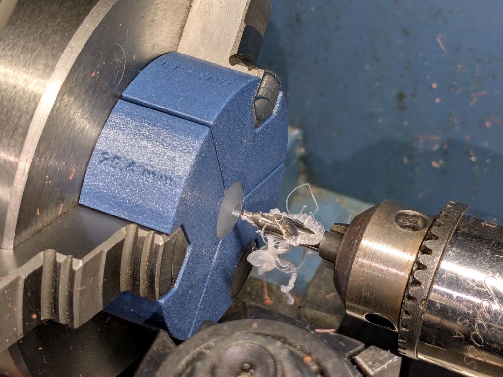
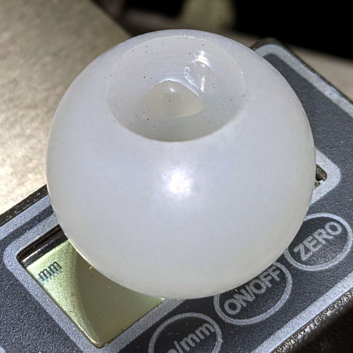
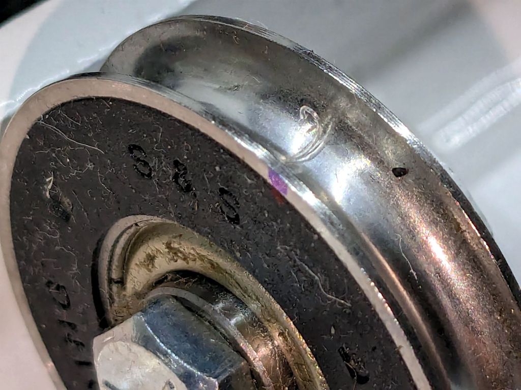
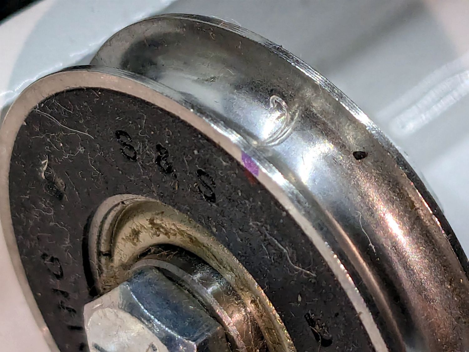
That thing looks like this up close:
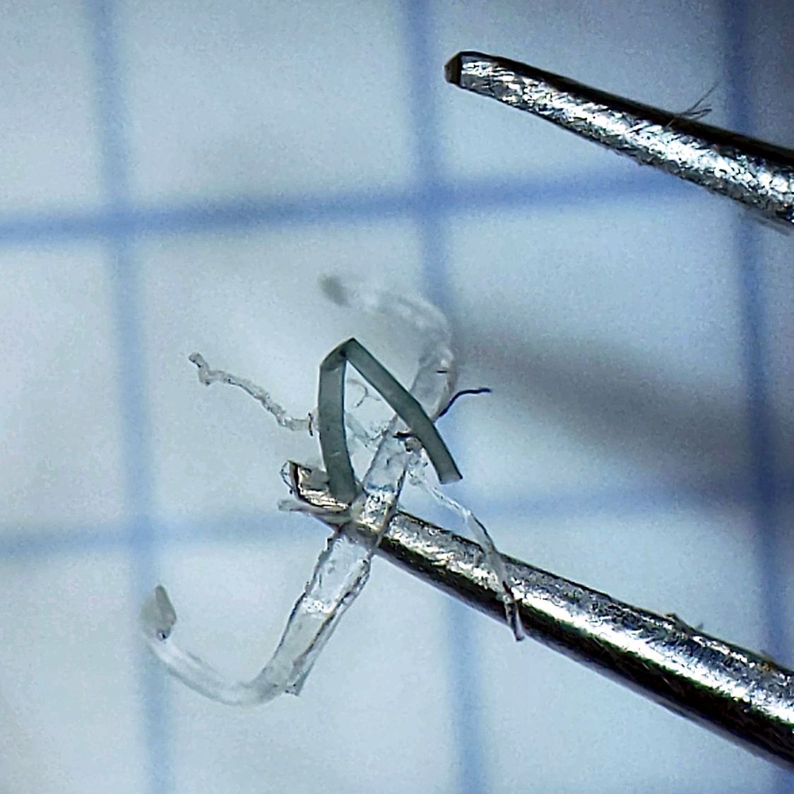
The fibers were almost invisible in my palm as I carried it upstairs to show it off.
Apparently, a few millimeters of plastic fiber dropped from space directly onto the track and got mashed into the wheel as it rolled along. Given the vast expanses of fabric & batting going into projects on a long-arm sewing machine, that crud could have come from anywhere.
As we now realize just how much trouble can come from a tiny bit of crud, finding the next hitch in the git-along will be easier.