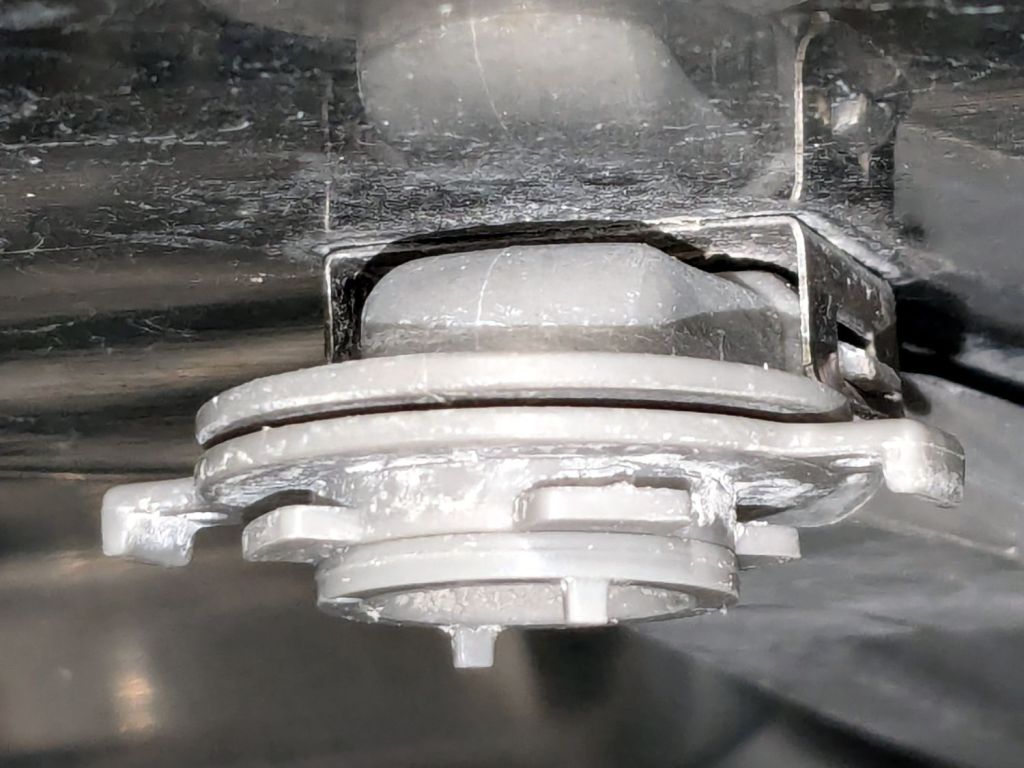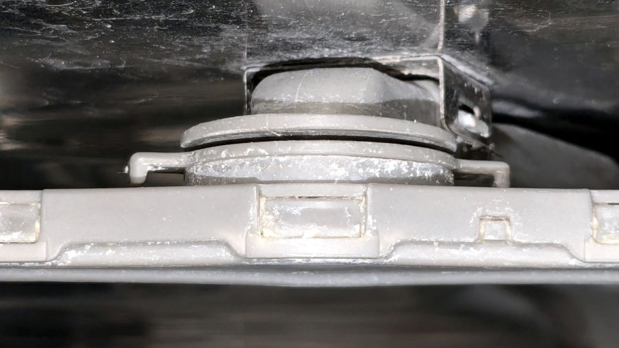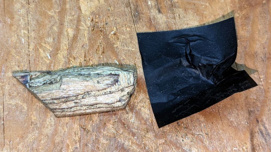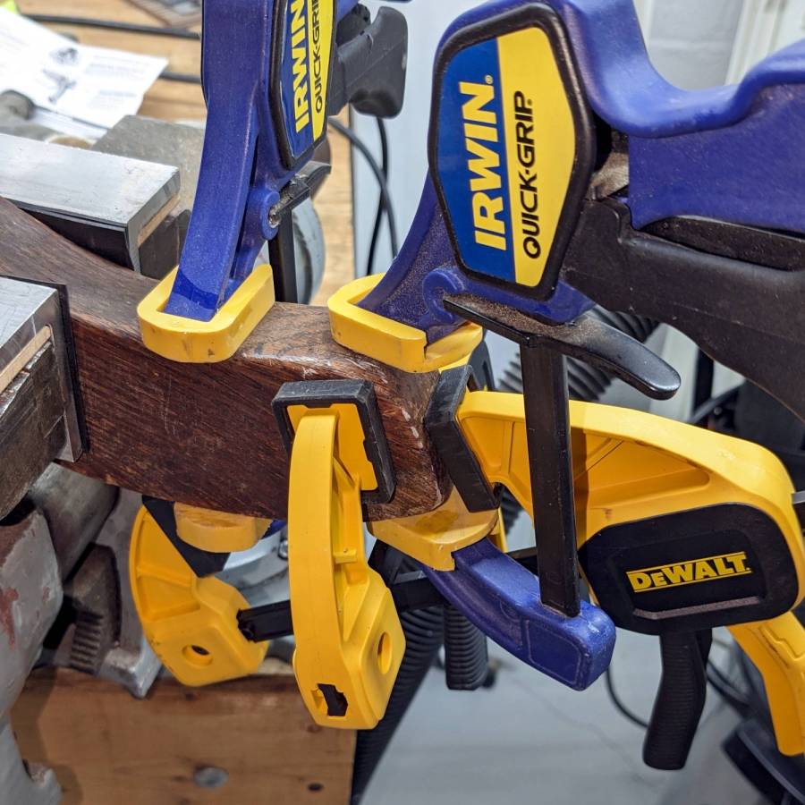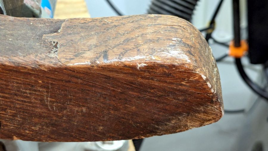
The Samsung range has ungainly cast-iron (or some such) grates that have long since worn out / lost their original Genuine Samsung rubber bumper feet. The grates had glued-on feet that looked very much like they belonged under something else, affixed with mystery adhesive that stuck firmly in some corners and let go in others:
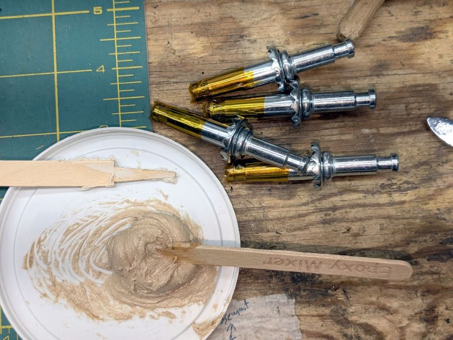
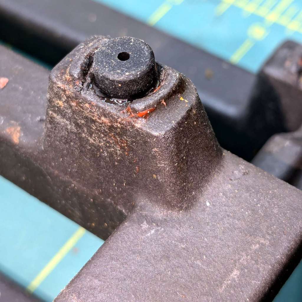
It seems Samsung no longer sells replacement feet, which may be an indication they don’t want customer complaints, so I got a bag of nominally compatible rubber feet from the usual source and broke out the cyanoacrylate glue:

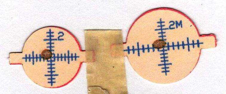
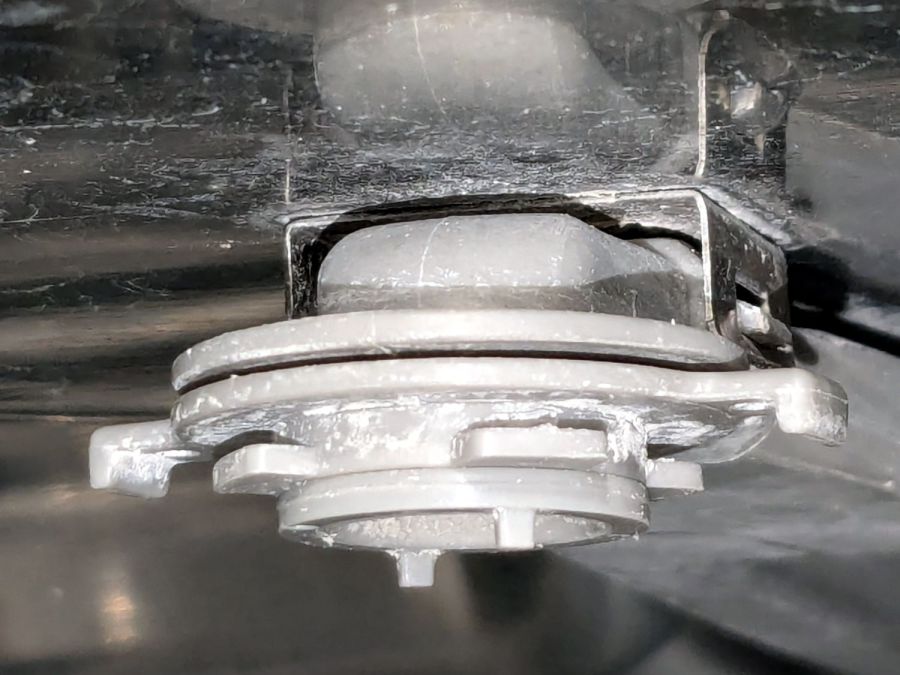
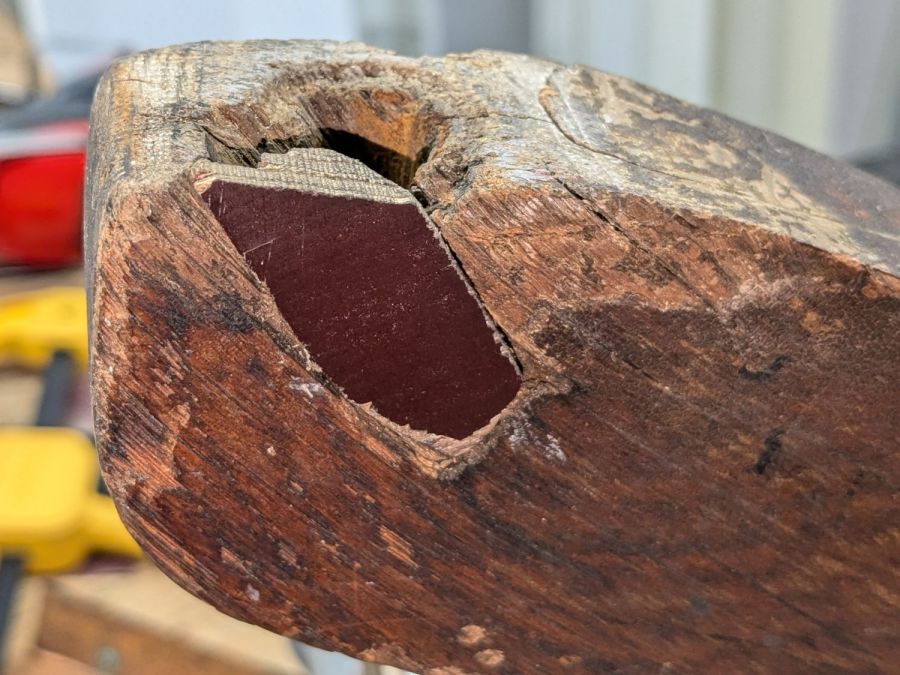
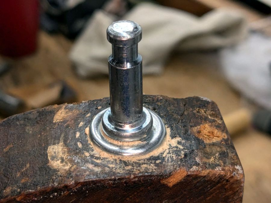
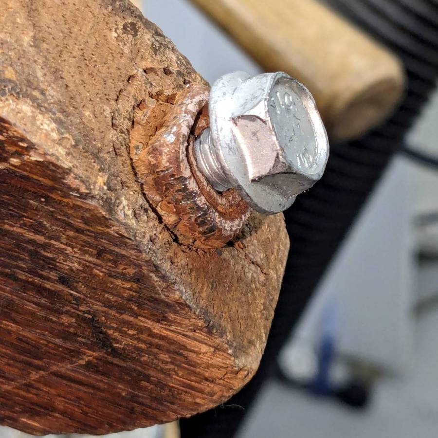
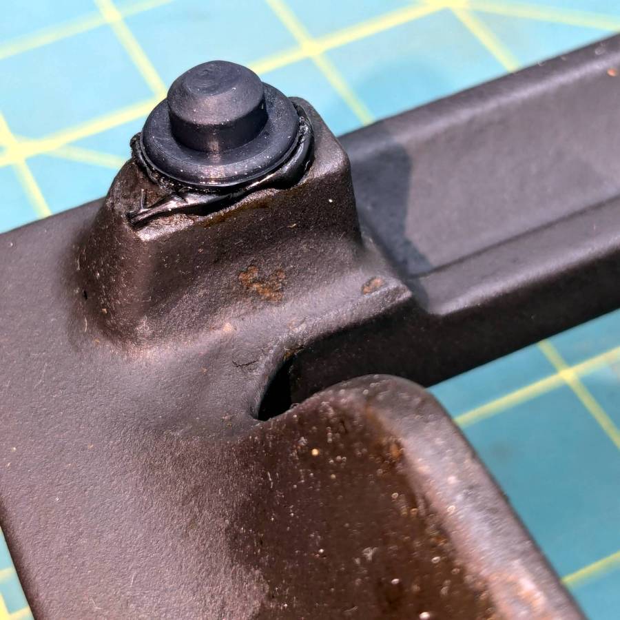
The red flecks are traces of a previous generation of adhesive, with the new cyanoacrylate peeking out around the base of the new foot.
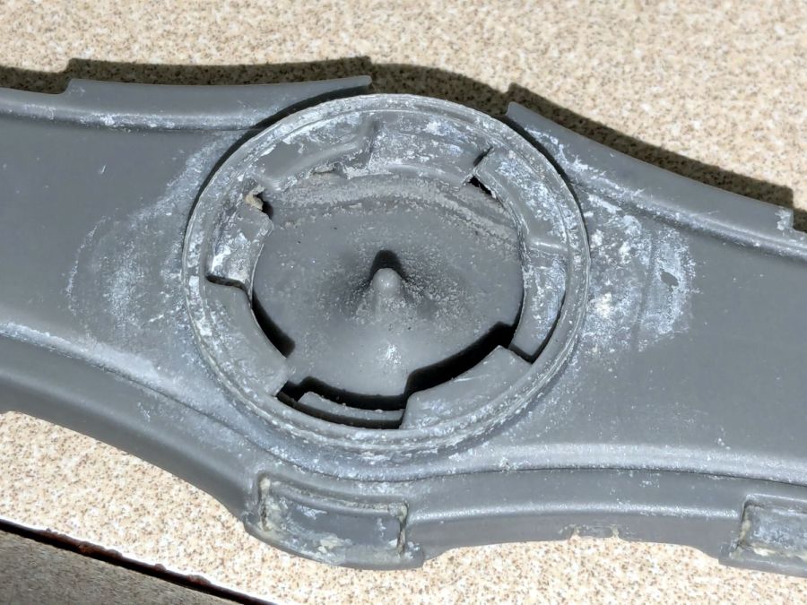
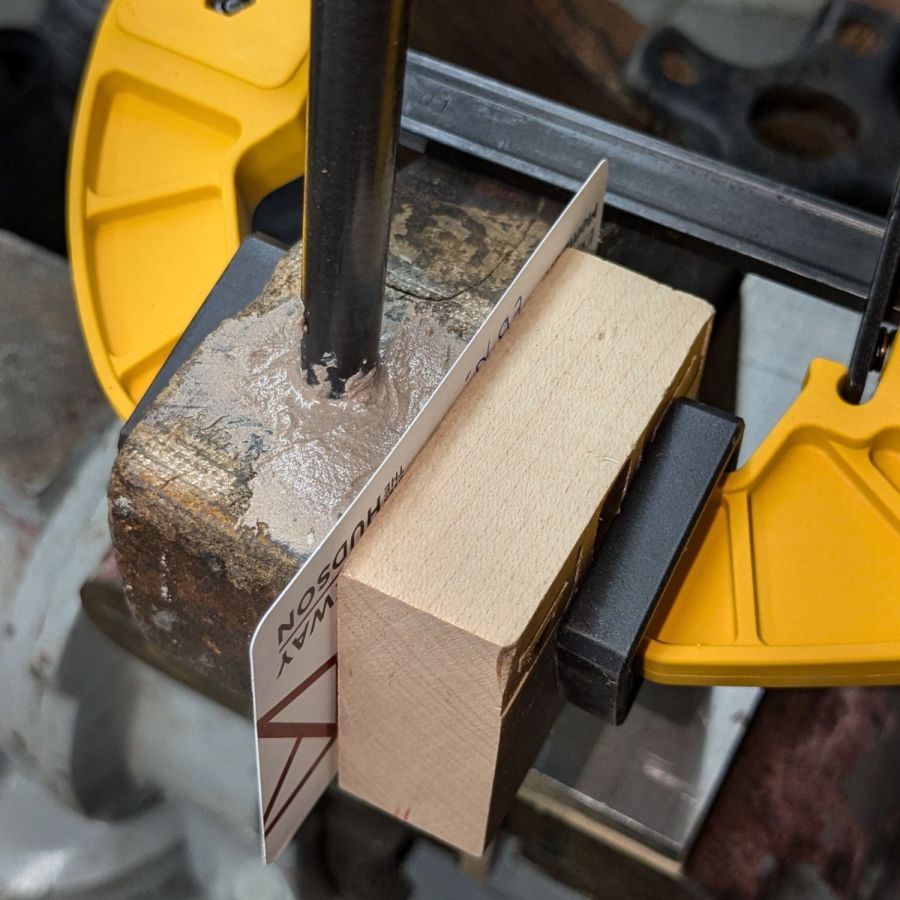
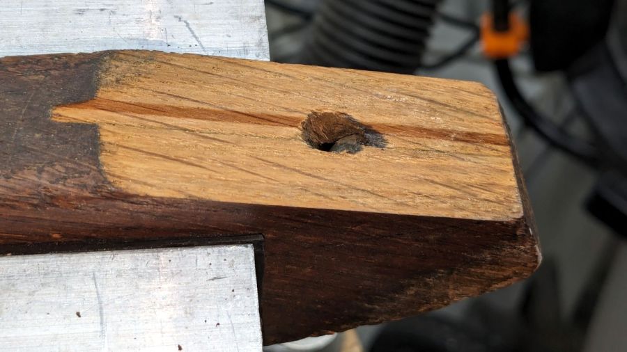
The grates have holes for the stems of the feet, so in principle they have plenty of resistance to being shoved around. In practice, tipping the grates up to clean underneath them dislodged the feet with depressing regularity. The grates are too heavy and too awkward to remove and plunk somewhere else, which suggests this sort of range is better suited to a kitchen that’s never used or, perhaps, comes equipped with a support staff.
You’re supposed to use high-temperature adhesive and, in fact, the red flecks look remarkably like high-temp silicone gasket compound, but all the missing feet were along the back of the grates where the small & simmer burners live, so I figured cyanoacrylate was certainly worth a try.
When & if they fall out, I’ll know when they went in.