Ed Nisley's Blog: Shop notes, electronics, firmware, machinery, 3D printing, laser cuttery, and curiosities. Contents: 100% human thinking, 0% AI slop.
I’m laying out a PCB with ampere load currents, millivolt sense voltages, and PWM drive, all connected to an Arduino’s strictly digital ground layout through the usual headers. While I’ve laid the board out with the high-current stuff over there, the sense inputs here, and the PWM as far off in its own corner as possible, I fear this will get ugly.
One step to reducing the noise involves a decent ground system. The Arduino pretty much eliminates the whole single-point ground concept, so I’m using a double-sided ground plane with plenty of Z-wire stitching , plus copper tape around the edge binding the top and bottom planes.
Copper tape on PCB edge
The PCB is 60 mils thick, so I cut four copper foil strips about 3/16-inch wide, folded them around the board edges, then burnished the surfaces flat.
Although the tape has adhesive on one side which is allegedly conductive, I figured running a solder bead along the edges couldn’t possibly hurt. That worked out reasonably well, if you don’t mind blobular solder along the edge of your board.
Copper tape solder joint
The joint along the bottom edge shows one problem: some adhesive oozed out while soldering and formed a barrier. I think that happened along the tape edges from the outside of the roll, because it’s most prominent along two board edges.
Memo to Self: Slice off and discard the outer few millimeters. Mask the outer board edge for a solid pour, not a hatch.
Because my hombrew circuit boards don’t have plated-through holes, I solder Z-wires from top to bottom. This entails little more than a solder blob around the wire on each side, but this time I wondered if having a slightly larger solid-copper area on each surface would be an improvement. Regrettably, I wondered this after masking the board.
Because I use an Ultra-fine-point Sharpie to touch up pinholes & suchlike, I decided to try it on larger areas by simply coloring in a few of the openings in the ground-plane grid.
Sharpie etch mask – Results 1
Short answer: doesn’t work so well.
However, I’m using direct etching: rubbing ferric chloride on the masked PCB with a sponge. The abrasion probably wears the Sharpie ink off the surface and then the copper begins etching as usual. If I were doing this with normal agitation / aeration, perhaps a Sharpie mask would work better.
This is also 1-ounce copper, so there’s twice as much etching going on. Perhaps half-ounce copper would vanish fast enough that the Sharpie mask would remain effective.
A bit more detail, with another Z-wire pointed right at you.
Sharpie etch mask – Results 2
The grid is 20-mil wide on 50-mil centers, with 25-mil isolation to other signals. The “via” holes use a 24-mil drill.
The row of dents just below the wire came from tiny openings in the mask that happen when Eagle poured the ground plane against the isolation surrounding the trace at the bottom. The toner-transfer resolution isn’t quite good enough to leave a clean opening and the etchant can’t quite reach the bottom to dig out the copper.
Memo to Self: Next time, try a 100-mil square pad around the via, centered on a grid intersection to fill in four adjacent openings.
On my way back from a ride around the block the back tire went pfft thump thump thump. I’m 1.5 miles from home: fix or walk?
The first step: always examine the tire to find the puncture, before you move too far. Finding something sticking out of the tire means you’re well on your way to fixing the flat. Lose the entry point and you’re left to blow up the tire and listen for escaping wind. So I picked up the butt end of the bike, spun the wheel, and this little gem heaved into view…
That area of the road has seen several collisions in recent months that left the shoulder littered with broken automotive glass. The shard in my tire glistened like a diamond, because one side was flat and mirrored; perhaps it’s from a headlamp reflector or side mirror. The pointy end went into the tire, of course…
Glass fragment and puncture
Well, a single-point failure like that is easy to fix, so:
remember that the hole is a few inches spinward of the label
shift to small chainring / small sprocket
get the tool bag out
lay the bike down (it’s a recumbent, this is no big deal)
release the rear brake
release the skewer and whack the hub out of the dropouts
apply tire irons to get the tire off
pop the tube out and examine the innards
No pix of any of that, but suffice it to say I was astonished to discover that the glass penetrated the Marathon tire’s Kevlar belt just barely far enough to poke the Slime tire liner, but not enough to leave more than a hint of a mark on the tube. Definitely not a puncture and certainly nothing that would account for a sudden flat.
That glass shard is not why the tire went flat! Tire liners FTW!
Examining the rest of the tube revealed this situation a few inches anti-spinward of the glass fragment.
Failed tube rubber
There’s a row of holes across the tube, with no corresponding tire or liner damage at all. As nearly as I can tell, the tube rubber simply pulled apart across that line, all at once, and the air went pfft just like you’d expect.
That’s not survivable, but I don’t carry a spare tube (well, two spare tubes: 700x35C rear and 20×1.25 front) on rides around the block. Long bike tours? Yup, spare tires & tubes because I’m that type of guy.
Anyway, I’ve got the tube in hand, so what’s to lose? Scuff it up with the sandpaper and yipes…
Tube after scuffing
What’s not obvious in the picture is that all those little spots around the big holes are pinholes. The whole area of the tube must have gotten just barely enough rubber to cover the mold.
I know as well as you do this isn’t going to have a happy outcome, but I slobber on the cement, let it dry, squash on a big patch, install the tube & tire, fire a 16-gram CO2 cartridge into it, and … it doesn’t seal.
The tube is several-many years old, probably from whoever was supplying Nashbar at the time, and it served well, so it gets a pass. I’d rather tubes fail in the garage than on the road and sometimes they do, but that’s not the usual outcome.
My ladies were out gardening at the time and a long wheelbase ‘bent isn’t the sort of thing you can stuff into a friend’s car. Not to mention that my ladies had the magic phone.
So I walked home.
Sometimes a man’s gotta do what a man’s gotta do.
Memo to Self: Schwalbe tube at 8910. Reversed(*) the Marathon’s direction.
(*)They’re directional, but when they get about halfway worn I don’t see that it makes much difference. The rear tire on my bikes wears asymmetrically: probably too many tools in the left underseat bag.
A friend donated an old Aptiva with an AMD K6 CPU to my collection. It’s too slow & power-hungry to be useful, so I harvested some useful bits and passed the corpse along to the recyclers.
As fate would have it, I have an upcoming project that needs a cooler, so I popped the fan off the top (it’s rotated a quarter-turn: those tabs lock over the edges of the heatsink) to see what’s inside…
Fuzz in AMD K6 CPU Cooler
That accumulation was pretty much invisible from the outside, with most of the fuzz clotted around the periphery of the fan duct. The fan blows downward into the heatsink, which acted (as usual) as a good dust filter.
A bit of vacuum cleaner work and it’ll be just fine.
Memo to Self:
The bottom of the heatsink is a 42×78 mm copper block with the heat pipes soldered into notches. Clearance from the block to the step below the widest part of the fins is 18 mm and the fins are 25 mm above the block surface.
Fan = 12 @ 70 mA. Reasonably quiet.
The small blue heat sensor (at about 8 o’clock in the picture) is upstream of the heatsink and, thus, measures ambient air . It’s essentially open-circuit at room temperature, but a diode test shows 1.4 V in either direction. That suggests it’s not a thermistor or thermocouple, but the CPU is old enough that it’s likely not a fancy IC, either. A puzzlement.
The Arduino Mega uses the ATMega 1280 chip to get more memory and far more analog & digital & PWM I/O pins, but remains more-or-less header-pin-compatible with the older Duemilanove and Diecimila boards (notes on the header coordinates for those boards is there).
Arduino Mega – ATmega1280 chip
Herewith, some useful coordinates for the Mega board in (X,Y) format using the default 0.001 grid: 1 unit = 0.001 inch (a.k.a 1 mil). Values are taken directly from the Eagle PCB layout.
The board outline is bounded by (2100,4000) on the upper right, with (0,0) at the lower left by the power jack. It’s not rectangular, but a conversation with Mr Belt Sander could remove the tab sticking out to the right beyond JP1/JP2 if that were really important.
The header names are not the same as on the old boards. Bolded values seem unusual.
PWMH 1×8 @ (1300,2000) ← X is not1290 as before!
PWML 1×8 @ (2150,2000)
COMMUNICATION 1×8 @ (3050,2000)
JP1 2×8 @ (3750,1550)
JP2 2×8 @ (3750,750)
POWER 1×6 @ (1550,100)
ADCL 1×8 @ (2350,100)
ADCH 1×8 @ (3250,100)
ICSP 2×3 @ (2555,1100) ← +5 X offset
Reset switch @ (2920,1100) ← -30 X offset
The PWMH header is 10 mils to the right of its position on the older boards, but still not on the same grid used by the other headers: it’s now offset by a nice, even 50 mils. This probably doesn’t matter for most headers, given the sloppy fit. If you have a finicky board setup, you’re in trouble.
Here’s what the PWMH and PWML headers look like, measured against a Duemilanove board on the top. The offset is not due to perspective!
Arduino Mega PWMH header offset
The Mega board has four 0.125-inch diameter mounting holes (they use 125.984, which is a hard-metric 3.2 mm). The first one is at the same position as on the Duemilanove board.
(600,2000)
(600,100)
(3550,2000)
(3800,100)
Three fiducials:
1 @ (780,2000)
2 @ (2319,1603) ← deliberately offset from the grid?
3 @ (3800,100)
Memo to Self: As always, verify these numbers before you start drilling!
The rear wheel of my bike popped a spoke while I was riding along a section of unimproved trail trail. Actually, it’d be more accurate to say “as-abandoned” railway line; they ripped out the ties and graded the baby-head ballast more-or-less level. It wasn’t really suitable for a long-wheelbase recumbent bike, but I really hate white-water rafting, which was the other choice.
Anyhow.
Of course, the broken spoke was on the sprocket side of the rear wheel. I discovered this when we were out of the most rugged section, so I have no idea how long I’d actually been abusing the wheel.
I released the rear brake, gingerly rode to the campsite, then installed the FiberFix emergency spoke I’ve been carrying around for a few years. After snugging the cord and tightening the nipple, I added a turn to each of the two adjacent spokes, making the wheel true enough to continue the mission.
FiberFix spoke in action
The other end simply passes through the spoke hole in the hub. It doesn’t mind the deformation pressed into the hub.
Hub end of FIberFix spoke
Much easier than removing the sprocket cassette under field conditions, that’s for sure!
Back home in the shop, I installed a new spoke, tightened it up to match the others, backed out the extra turn in the adjacent spokes, and the wheel trued right up.
I originally built the wheel using a Park Spoke Tension Meter, which is a wonderful tool. If you build wheels, even occasionally, you really, really need one. Lace ’em up, tighten uniformly, then tweak just a little bit for a perfectly true wheel.
And, yeah, Phil hubs on all three bikes. I hate adjusting bearings. The man is gone; may his legacy live forever.
One of those midnight “I heard such a clatter” events: somebody or something was kicking a can all over the driveway.
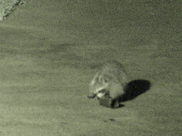
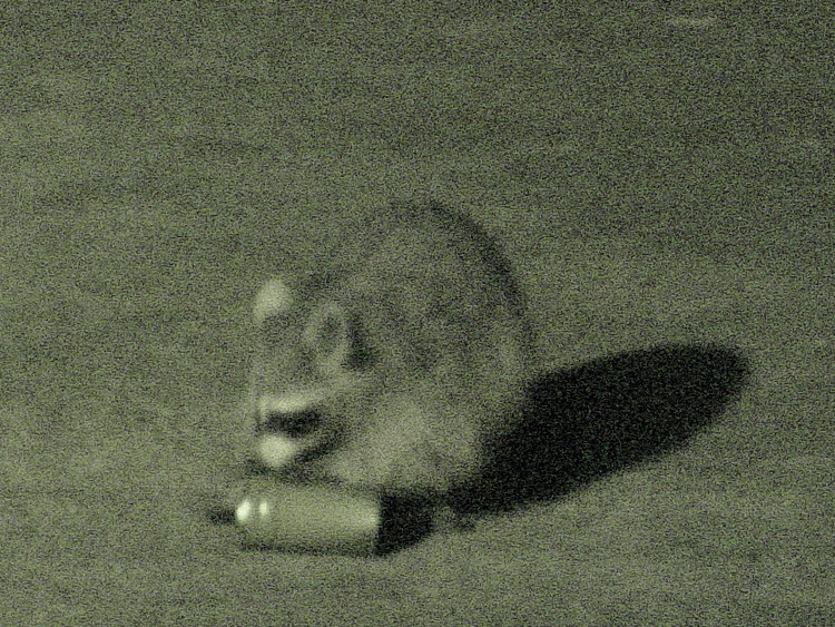
Turned out that a raccoon found the stack of carefully rinsed salmon cans in the recycling bin and was puzzling over how to get them apart. Evidently he figured there was something really delicious hidden in there somewhere!
I had time to fiddle with the camera before he gave up and wandered away on his rounds…
Raccoon vs cans – 1
Raccoon vs cans – 2
Raccoon vs cans – 3
Raccoon vs cans – 4
Raccoon vs cans – 5
Raccoon vs cans – 6
These are in near-IR “Nightshot” mode with my ancient DSC-F717 and the 1.7X teleconverter. They’re automagic crops from larger frames, walloped en masse with ImageMagick:
for f in *jpg ; do mogrify -crop 1200x900+700+450 -resize 750x563 $f ; done
The gritty texture plays hell with JPEG compression, but that’s what the camera delivers. An incandescent spotlight on the driveway contributes the deep shadow, but an ordinary camera (my DSC-H5) produced completely black images, even with the high-power flash setting.
Memo to self: start keeping the recycling bin inside the garage. But will that just piss off the bears that are moving (back) into the county?