Ed Nisley's Blog: Shop notes, electronics, firmware, machinery, 3D printing, laser cuttery, and curiosities. Contents: 100% human thinking, 0% AI slop.
Setting up the Makergear M2 to print TPU (eSun 95A) involved a cold pull to get the remaining PETG out of the nozzle, some manual flushing, then printing test cubes to figure out a reasonable speed / temperature combination:
Makergear M2 – first TPU test cube
A 10 mm solid cube came out overstuffed and the first 20 mm cube lacked enough infill to hold its top up, but the third cube looked surprisingly good at 230 °C and 30 mm/s with 15% 3D Honeycomb infill:
Makergear M2 – TPU test cubes
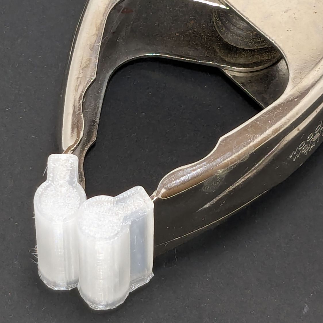
With that settled, I conjured pairs of soft (-ish) jaw pads for the far-too-many metal spring clamps having worn out their vinyl pads:
Spring clamp jaws – installed
Those were the first attempt and worked well enough to suggest nicely rounded endcaps instead of flat cylinders:
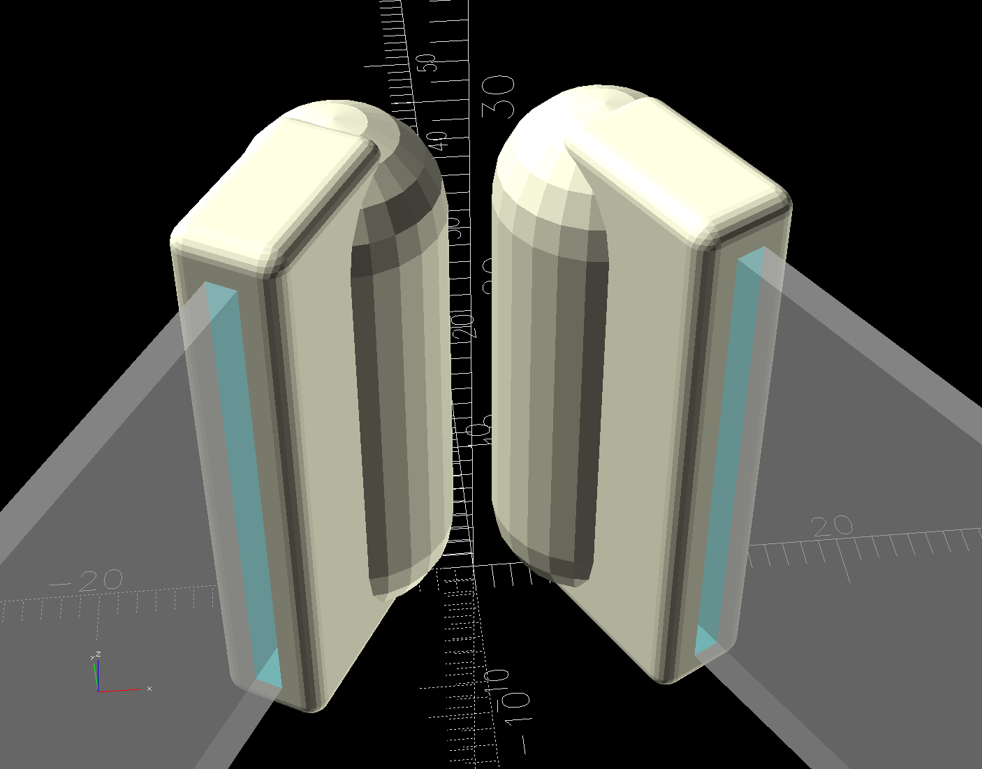
Spring Clamp Jaws – show view
Unlike the first version, they now build standing on their rectangular clamp jaw opening:
Spring Clamp Jaws – show view
Those two groups have different lengths (1 inch and 1-⅛ inch) with PrusaSlicer combining the OpenSCAD program’s output.
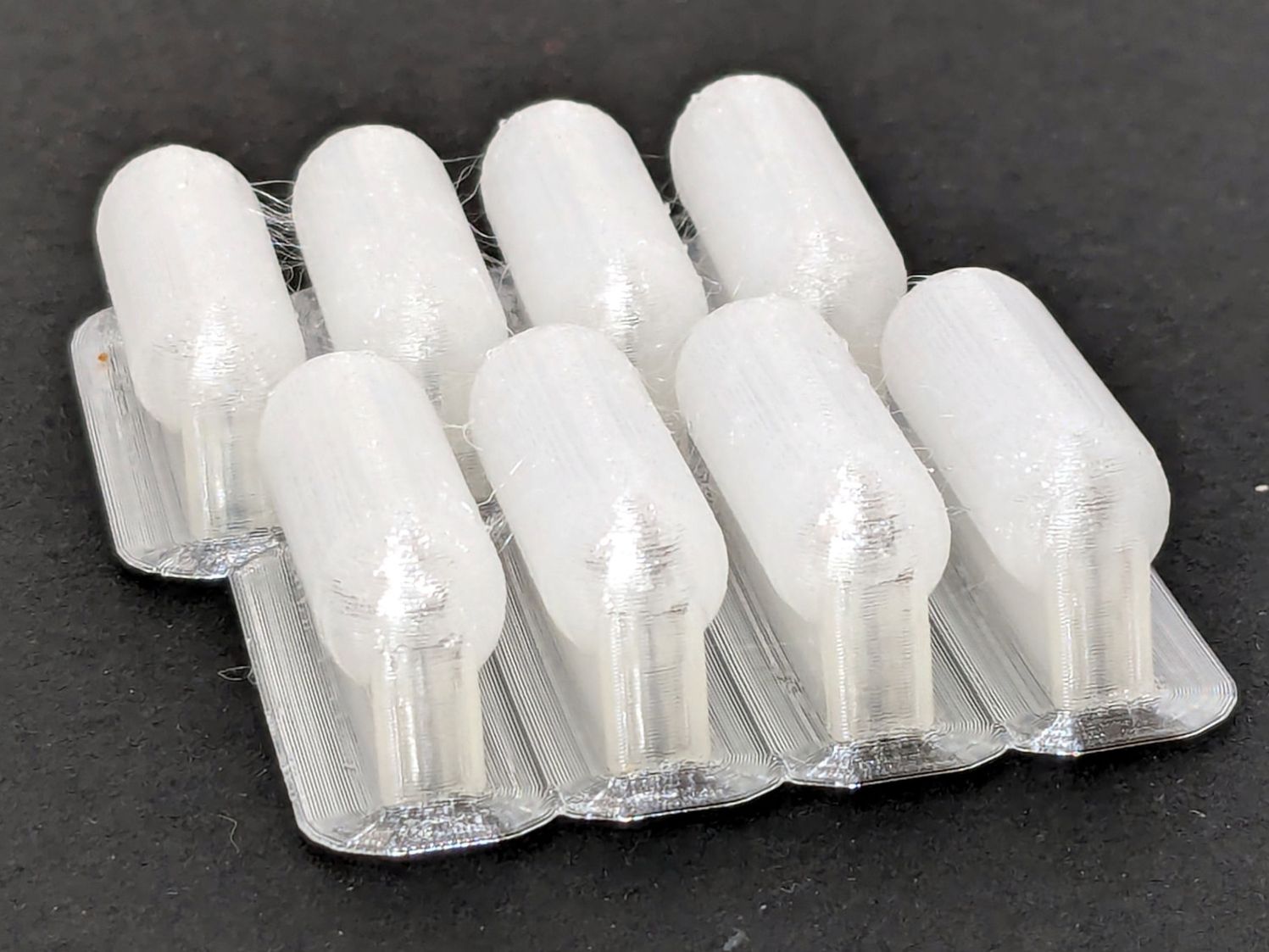
The as-built pads are essentially un-photographable:
Spring clamp jaws – group build
TPU is tough enough to make the single-layer brim un-tearable, but they’re easy enough to separate & trim with scissors. Even the 5 mm brim has a tenuous grip on glass + Suave hair “spray” applied from a dropper bottle, so I should try a BuildTak sheet that’s been on the to-do pile for far too many years.
Similarly, TPU is flexy enough to make a precise fit unnecessary: push firmly to force the pads onto the jaws and you’re done.
This file contains hidden or bidirectional Unicode text that may be interpreted or compiled differently than what appears below. To review, open the file in an editor that reveals hidden Unicode characters.
Learn more about bidirectional Unicode characters
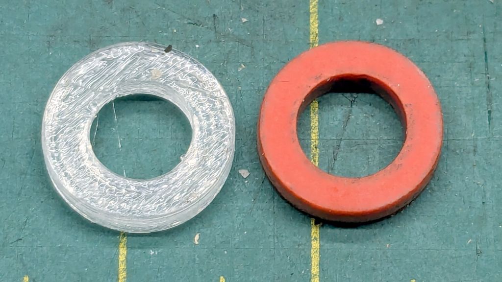
There being nothing like a good new problem to take one’s mInd off one’s old problems, I set the Makergear M2 to printing TPU and made a washer for the Champion Hose Nozzle:
Champion hose nozzle – TPU vs rubber washers
It turns out PrusaSlicer can produce models for simple shapes using the Shape Gallery. Subtracting a 7.5 mm cylinder (as a “negative shape”) from a 12.7 mm = ½ inch cylinder does the trick, with the washer all of 2.5 mm thick.
The ID of the thread inside the nozzle is slightly smaller than 12.7 mm, but TPU is bendy enough to let me push it through sideways and reorient it against the front of the nozzle.
The conical part of the nozzle seals against the washer, leaving only a very slight ooze of water, and opens far enough to produce a jet. The TPU is solid enough to not vibrate in the flow and the nozzle no longer howls at low flow rates.
None of the other nozzles in the box have a washer up in there, so they all depend on a much better machined fit than I achieved.
At least the Champion nozzle is once again usable, should it ever emerge from the bottom of the box.
So I loaded up the same STL in Prusaslicer and made three more:
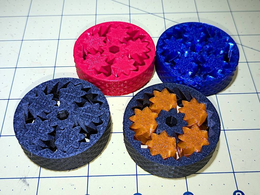
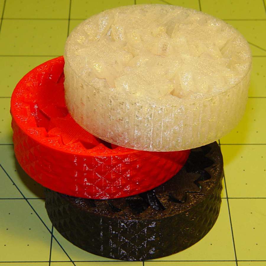
Planetary Gear Bearing – M2 vs MK4
Both pictures show the same red bearing, done in PLA on the Makergear M2. The other bearings are PETG and PETG-CF on the Prusa MK4 + MMU3.
The blue bearing has about 5 mm of axial play, a bit more than the red.
The gray bearing is PETG-CF and has maybe 1 mm of axial play, which agrees with my original observation that an Extrusion Multiplier of 1.0 results in slightly overstuffed carbon fiber parts. It’s not much and, frankly, produces a better fit in this case, but it’s different than pure PETG. Which should come as no surprise, of course, given that it’s 15% carbon.
The gray-and-orange bearing looks spectacular in person and has about 3 mm of axial play, roughly the same as the red bearing, which you’d expect from overstuffed PETG-CF and pure PETG.
The single-color bearings print in about 1.5 hours and the two-color one weighed in over four hours. Multi-material objects are do-able, but you gotta want the results.
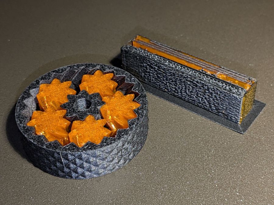
I told Prusaslicer to wipe the orange filament into the gray infill during color changes (per the Wipe Tower doc), but those two gray parts have so little infill as to make no difference:
Planetary Gear Bearing – PETG PETG-CF with wipe tower
The wipe tower in that posed photo has a nubbly texture because the filament just gets squirted without regard to anything other than maintaining the basic tower shape.
Seeing things appear on the platform never gets old!
A glass-top patio table came with our house and, similar to one of the patio chairs, required some repair. The arched steel legs fit into plastic brackets / sockets around the steel table rim under the glass top:
Glass patio table – new brackets installed
The four glaringly obvious white blocks are the new brackets.
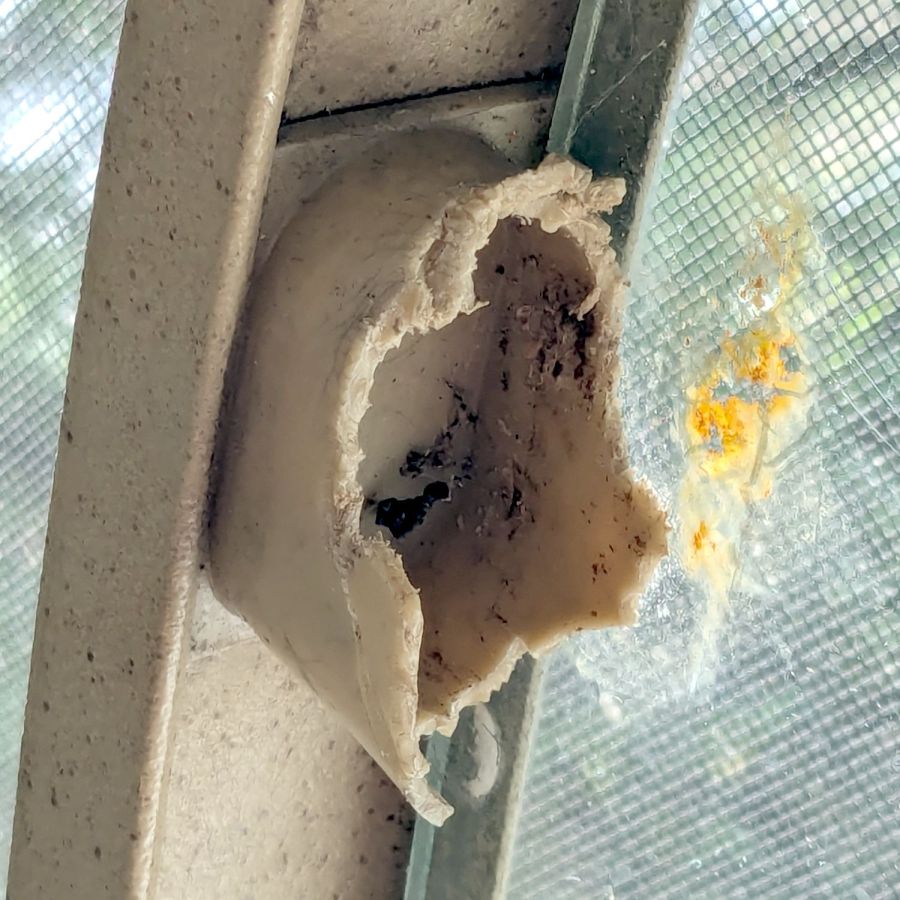
The original brackets had, over uncounted years, deteriorated:
Glass patio table – failed OEM bracket
Perhaps disintegrated would be a better description:
Glass patio table – crumbled OEM bracket
Each leg has a pair of rusted 1-½ inch ¼-20 screws holding it to the central ring. As expected, seven of the eight screws came out easily enough, with the last one requiring an overnight soak in Kroil penetrating oil plus percussive persuasion:
Glass patio table – jammed screw
The four legs had three different screws holding them to the brackets, so I drilled out the holes and squished M5 rivnuts in place:
Glass patio table – M5 rivnut installed
Although it’s not obvious, the end of that tube is beveled with respect to the centerline to put both the top and bottom edges on the table rim inside the bracket. In addition, the tube angles about 10° downward from horizontal, which I did not realize amid the wrecked fittings, so the first bracket model failed instantly as I inserted the leg:
Glass patio table – first bracket test
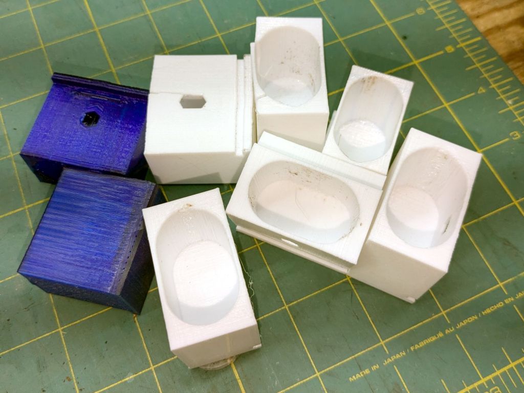
The top & bottom walls of that poor thing were breathtakingly thin (to match the original bracket) and cracked when confronted with the angled tube. I could not measure all the sizes & angles without assembling the table on trial brackets, so getting it right required considerable rapid prototyping:
Glass patio table – failed brackets
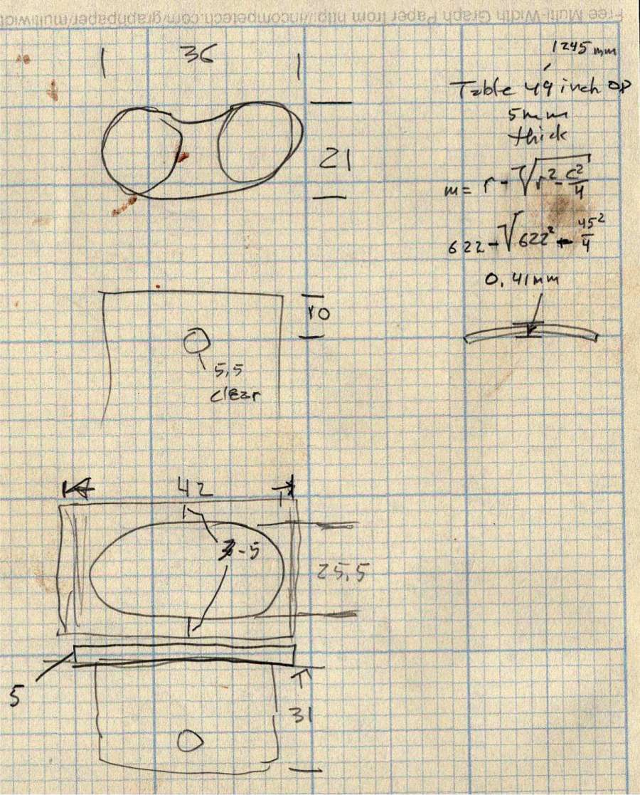
Some trigonometry produced a solid model with features rebuilding themselves around the various sizes / angles / offsets:
Glass Top Table – leg bracket – solid model
A sectioned view shows the angled tube position and end chamfer:
Glass Top Table – leg bracket – section view
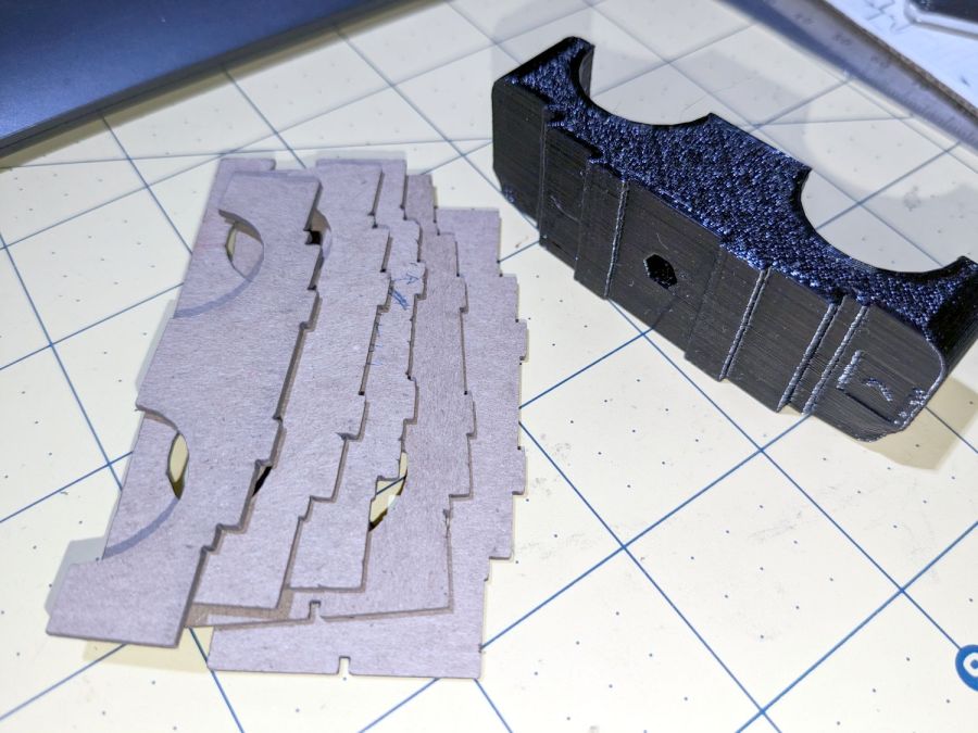
The OpenSCAD code can produce a sectioned midline slice useful for laser-cut MDF pieces to check the angle:
That eliminated several bad ideas & misconceptions, although trying to balance the leg on a 3 mm MDF snippet was trickier than I expected. In retrospect, gluing a few snippets together would be easier and still faster than trying to print a similar section from the model.
The slightly elongated slot for the M5 screw shows that the original screw holes were not precisely placed or that the tubes were not precisely cut, neither of which come as a surprise. I finally built some slop into the design to eliminate the need for four different blocks keyed to four different legs.
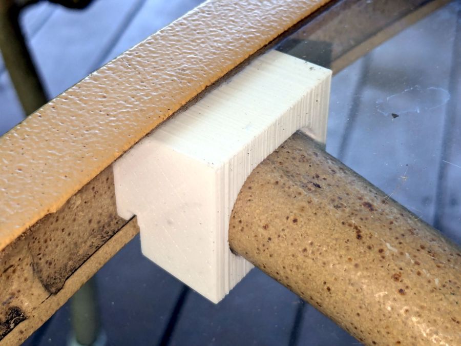
The outer rim, the notch on the bottom, and the tab on the top curve to match the four foot OD glass tabletop, with the inward side & ends remaining flat:
Glass patio table – chunky bracket installed – top
The sector’s difference from a straight line amounts to half a millimeter and improved the fit enough to justify the geometric exercise. The bracket snaps into position with the notch over the table rim and the tab locked in the gap between the glass disk & the rim, although I suspect the weight of the tabletop would keep everything aligned anyway.
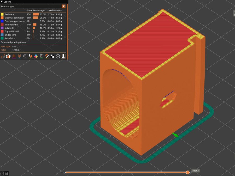
The walls are now at least 4 mm thick and, printed in PETG, came out strong enough to survive assembly and some gentle testing. They’re arranged to print on their side to eliminate support under those slight curves and to align the layers for best strength vertically in the finished bracket:
Glass Top Table – leg bracket – slicer preview
The leg cavity and screw hole built well enough without internal support.
They’re relentlessly rectangular and I’m not going to apologize one little bit.
Now to see how they survive out there on the screened porch.
This file contains hidden or bidirectional Unicode text that may be interpreted or compiled differently than what appears below. To review, open the file in an editor that reveals hidden Unicode characters.
Learn more about bidirectional Unicode characters
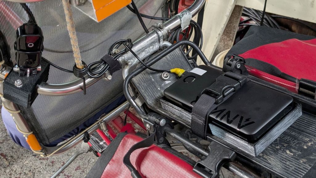
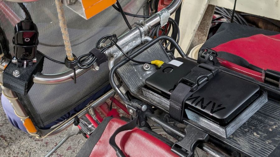
The Anker 325 20K V2 power bank is considerably chunkier, as befits its 20,000 mA·hr cell capacity (although the fine print says 12,500 mA·hr output):
Anker 20K V2 Power Bank – installed
The white tape stripe on the top marks the USB port on the end to reduce the fumbling involved in an out-of-sight socket. There’s also a USB-C port on that end for both charging the pack and powering other devices.
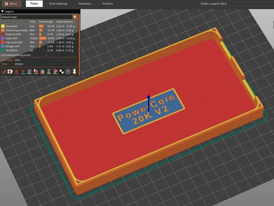
The new mounting cradle descends directly from the 13000 cradle:
Anker 325 20KV2 Power Bank – slicer preview
The model includes a projection of the battery on the XY plane for export to an SVG file suitable for laser-cutting an EVA foam pad to cushion the bumps.
The mounting block under the electronics box for the new UPP battery has a recess for an M5 tee nut:
UPP Battery Mount – Block 5 Show View
As with the Terry frame mounts, I glued the modified tee nut in place with JB Plastic Bonder urethane adhesive, did a test fit on the bike, discovered the whole affair had to sit about 10 mm forward, put the new frame measurement into the OpenSCAD code, and ran off a new block.
Which gave me the opportunity to perch the old block atop the bench vise with the tee nut aimed downward between the open jaws, run an M5 bolt into the nut, and give it a good thwack with a hammer:
UPP Battery Mount – M5 insert adhesive test
Although the urethane adhesive didn’t bond uniformly across the tee nut, it had enough grip to tear the PETG layers apart and pull chunks out of the block.
As with the tee nuts on the Terry bike, this one will be loaded to pull into the block, so it will never endure any force tending to pull things apart, but it’s nice to know how well JB Plastic Bonder works.
I chiseled the PETG and adhesive debris off the tee nut, cleaned it up, slathered more Bonder on the new block, and squished the nut in place. After I get the electronics box sorted out, the whole affair will never come apart again!
The top profile fits snugly into the battery mounting plate, with clearance on the sides for the latches:
UPP Battery Mount – trial fit
However, I had enough trouble measuring those recesses that I broke down and added a projection() view to the OpenSCAD code:
UPP Battery Mount – profile
Exporting that as an SVG image and importing it into LightBurn let me cut it out of chipboard:
UPP Battery Mount – laser cut profiles
Obviously, it took several iterations to fit the top profile to the baseplate, particularly after finding slightly different measurements at each block position. On the other paw, laser cutting the profiles proceeded much more quickly than 3D printing just a few millimeters of the block, so it was a net win.