Ed Nisley's Blog: Shop notes, electronics, firmware, machinery, 3D printing, laser cuttery, and curiosities. Contents: 100% human thinking, 0% AI slop.
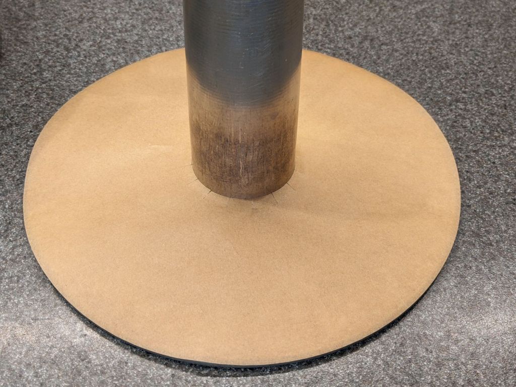
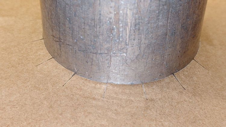
Radial slits around the middle let it bend upward over the folded aluminum joint around the pillar:
Angel Food Cake Pan liner – detail
Ours claims to be a 10×4-½ inch pan, roughly the diameter at the top and the overall height. Your pan will surely be different: this one is, as the saying goes, old enough to know better.
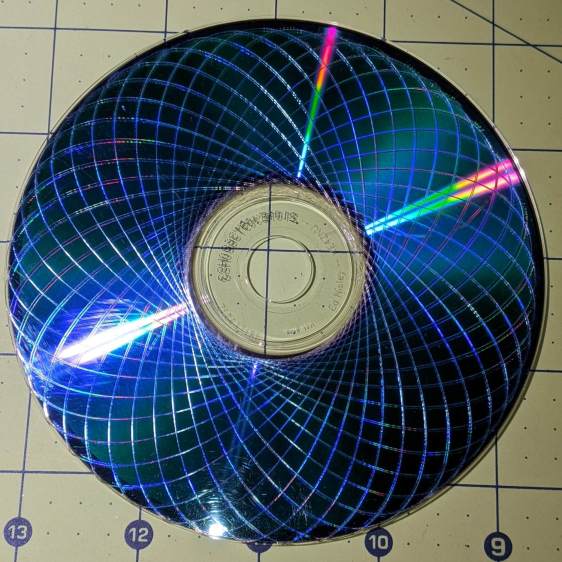
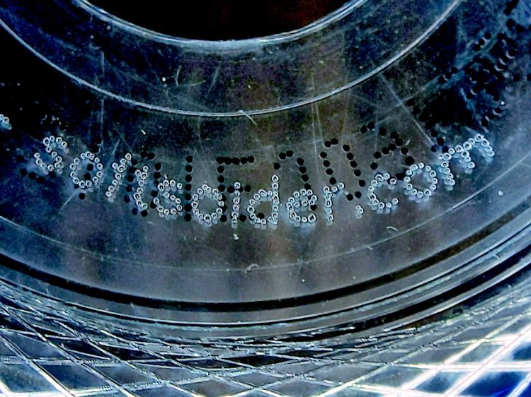
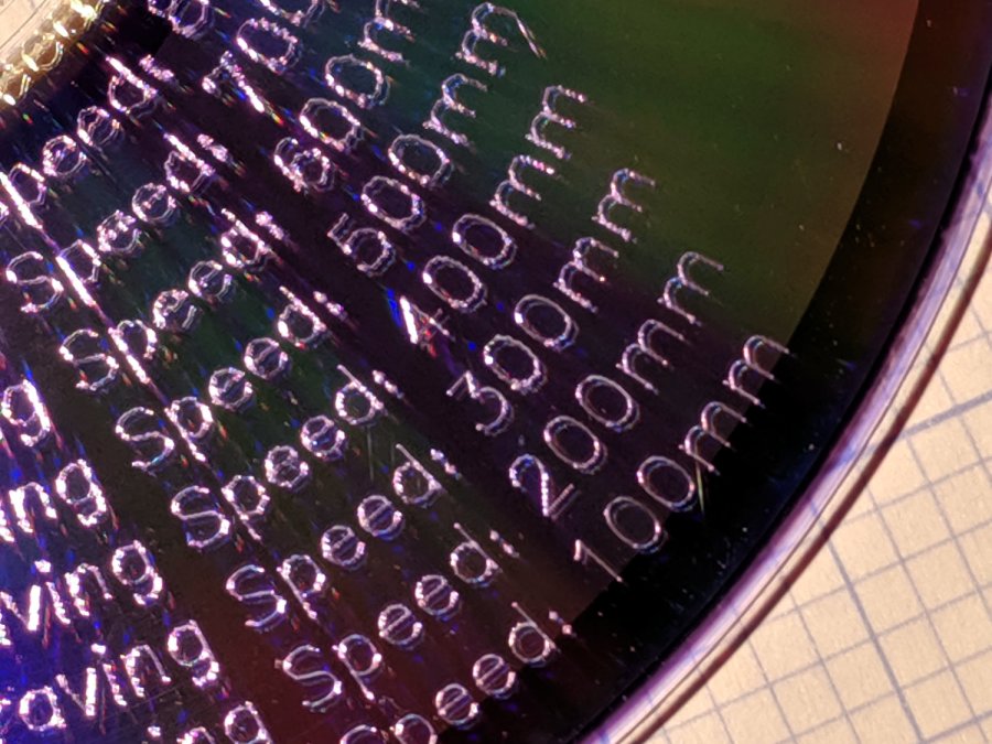
The legend around the middle came out well with 2 ms pulses at 0.25 mm spacing:
Laser-engraved DVD – dot-mode text detail
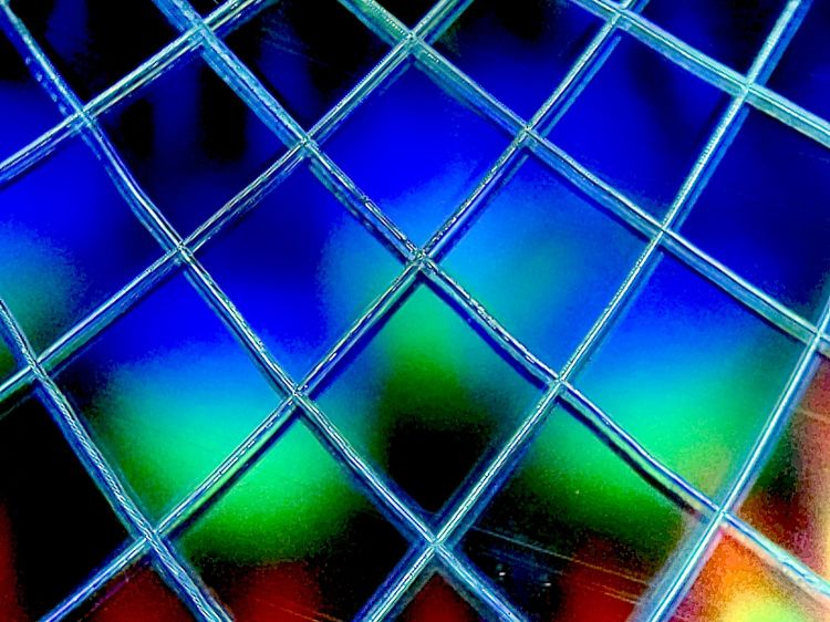
The black dots in the background were printed on the label side of the DVD.
The vast number of closely spaced points caused the laser’s path planner to pause the machine’s XY motion while it caught up, but without visible damage to the platter. The GCMC program prunes the path to ensure successive points lie more than 0.2 mm apart, but maybe coarser resolution would reduce the planner’s workload without looking any worse.
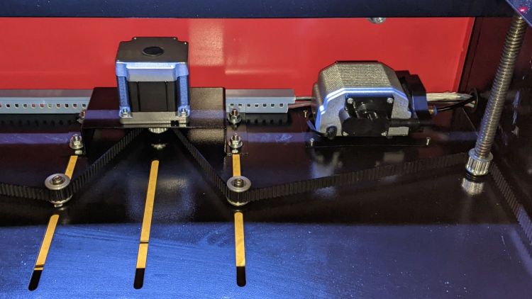
The OMTech 60 W laser gets its air assist from an aquarium-style air pump in the right rear of the cabinet:
OMTech 60W laser – Z motor – air pump
Since that picture, I’ve sealed the slots for the Z-axis belt tensioner pulleys.
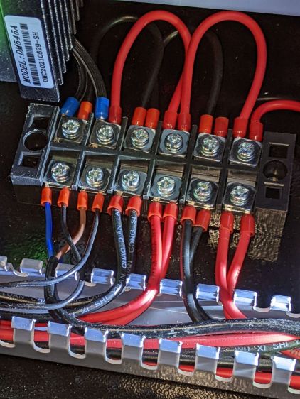
The pump is connected directly to the AC line at the main barrier block (blue and brown on leftmost two terminals):
OMTech 60W laser – AC barrier strip
Even though the pump has very flexy rubber feet, it’s annoyingly noisy and should be off when the laser beam is off.
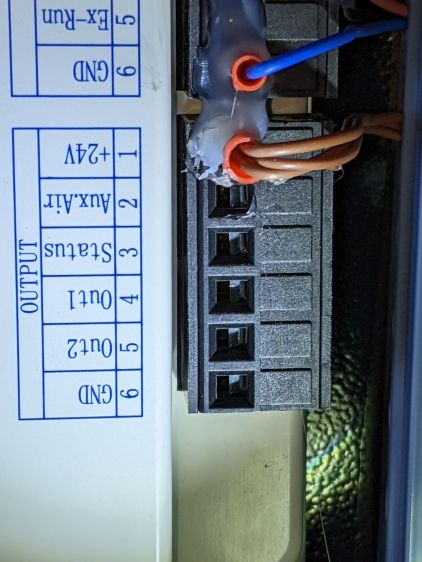
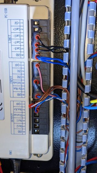
The knockoff RuiDa KT332N controller (possibly by Ryxon, based on a LightBurn forum thread, but without a visible name anywhere on the hardware or in the manual) has an Aux.Air output terminal:
KT332N Controller – output wiring plug- glued
Yes, the controller is mounted that way inside the electronics bay.
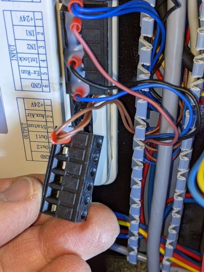
Chipping away the hot-melt glue over the terminals lets you pry the terminal block out of the controller:
KT332N Controller – output wiring plug
The KT332N manual describes the Aux.Air pin 2 function:
Dedicated output. When auxiliary air control is enabled, this port outputs a control signal to control the valve or other relay to release auxiliary air. This port is multiplexed with pen control signal. When auxiliary air control is disabled, this port is assigned as pen control. The output type is open collector. The output can be set to be synchronized with laser or synchronized with work.
Section 4.6 — General and dedicated output
The word “pen” does not occur anywhere else in the manual, so I have no idea what it might mean. Perhaps the controller can also become a pen plotter?
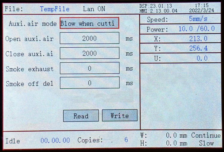
A configuration screen (Menu → Para Setting → Auxi.Air) gives the options:
KT332N Controller – Air Assist Config screen
Section 9.2 of the manual describes the choices, although not quite in the same words:
Blowing method:The way of the air is blown during processing. Can be configured to output fire, process gas, and manual gas.
Blow on delay:Delay time after turning on air blowing
Blow off delay:Delay time before turning off the blow
Section 7.2 gives the electrical parameters:
All output signals of this controller are output based on opto-coupler isolation technology and OC gate output. Its maximum driving capacity is 300mA, which can directly drive 6V / 24V relays, light-emitting indicators, buzzer alarm devices, etc.
Section 7.2 — Output
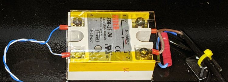
I wired an AC solid state relay (surely a counterfeit Fotek) in series with the pump’s AC Line wire:
KT332N Controller – Air Assist SSR installed
It’s firmly stuck to the bottom of the electronics bay with heatsink tape, not that it gets particularly warm switching a few dozen watts of pump.
Because the output pin is active low, the SSR + input comes from a ferrule jammed into the 24 V supply pin on the controller, along with the original ferrule holding three other wires:
KT332N Controller – Air Assist SSR wiring
With all that in place, I turned it on and … the air pump did not turn on when I ran the next job. I could manually turn the pump on with the front panel Aux Air button, but it shut off as soon as I ran a file.
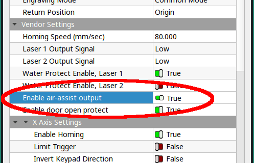
The “enable” setting referred to in Section 4.6 appears in the Vendor Parameters:
Enable the auxiliary air control : If you want to use the Wind signal of the output port to control the fan switch in layers, you must enable this parameter. Otherwise, the Wind signal outputs other signals.
Section 9.1 — Vendor Parameters
The Vendor Settings are protected by a password I don’t know do not appear in the section of settings I assumed they would be in, based on the manual’s wording. It seems an external program connected to the controller by USB or the network provides the only way to access these settings.
Fortunately, LightBurn exposes the Vendor settings after you click through a warning dialog:
LightBurn Vendor Config – Air Assist Enable
And then It Just Works™.
The “Blow when laser” option turns on the pump whenever the laser power supply is producing a beam, so it switches on and off at a furious pace. This is not the option you are looking for.
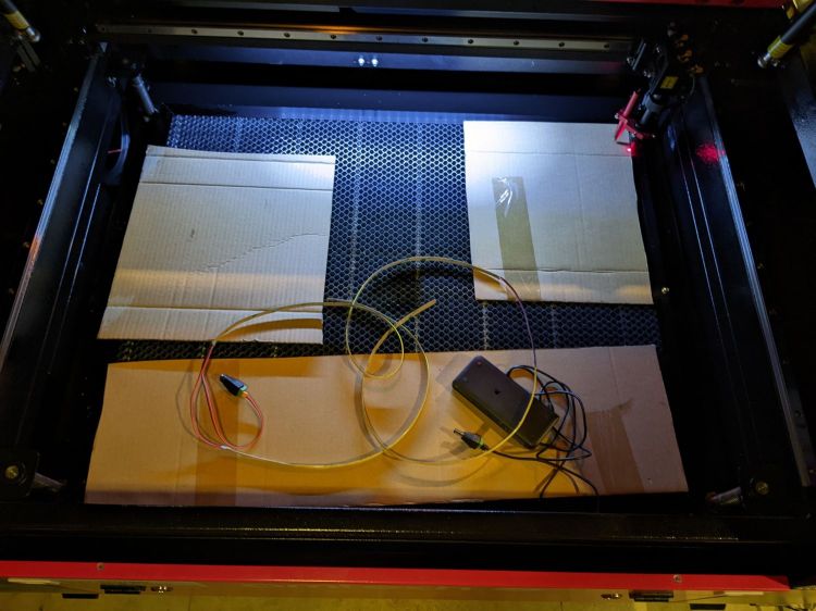
The OMTech 60 W laser arrived with an LED strip light under the gantry:
OMTech 60W laser – OEM lighting
That works reasonably well, if only because the pool of light travels with the gantry, but it’s always behind the area where you’re (well, I’m) setting up the Thing To Be Cut. An overhead can lamp with a warm-white CFL bulb contributes the yellowish foreground lighting, although I cast a big shadow when leaning into the cutter.
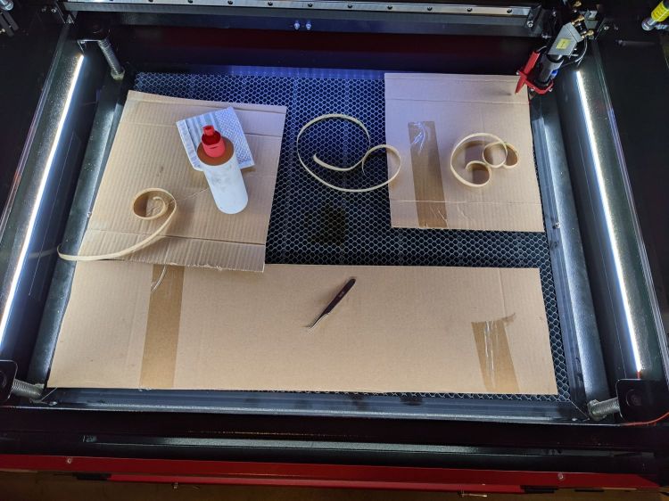
Adding three COB LED strips along the sides definitely improved the situation:
OMTech 60W laser – COB LED strips
The glare will require shades along their top, but that’s in the nature of fine tuning.
I got 24 V COB LEDs to match the cutter’s power supply and reduce the overall current along the strips, but upon further inspection the OEM power supply seems under-specified for its job. The XY stepper drivers each draw 3.5 A peak, the Z (they call it U) axis driver is set for 5.1 A peak, and the knockoff RuiDa controller also runs at 24 V with an unspecified current.
Rather than stress the OEM supply, some rummaging in the Big Box o’ Wall Warts produced the 24 V 2 A power brick shown in the first picture. The previous owner had cut off the no-doubt specialized connector, so I had no qualms about splicing in a 5.1 mm coaxial power plug.
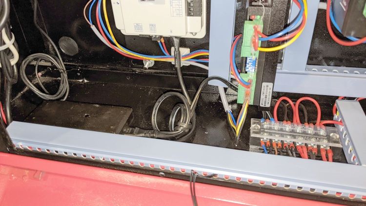
On the other end, I amputated the AC line plug, crimped on a pair of ferrules, and inserted them into the AC power barrier strip inside the electronics bay:
OMTech 60W laser – LED power supply
Yes, that little smudge in the middle of the brick is an Genuine Embossed Apple logo, so you know it’s gotta be good.
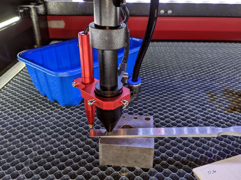
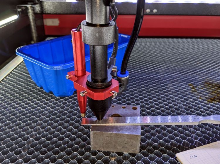
The OMTech 60 W laser cutter has an 18 mm lens with a 2 inch = 50.8 mm focus distance:
OMTech 60W laser beam test – focus point
The tip of the cone sits 18 mm over the focal point.
The red “pen” is the auto-focus probe switch. It has essentially zero overtravel after tripping, with enough pretravel to hover barely 6 mm above the focal point.
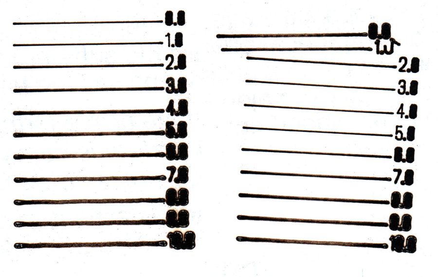
Lightburn can produce a focus test pattern:
OMTech 60W laser – focus test patterns
The left pattern comes from a piece of paper with the focus point at the surface, corresponding to the “0.0” line.
The right pattern is on another piece of paper atop a 3 mm cardboard sheet, so the “0.0” line sits 3 mm above the focal point. The pen tip brushed a protruding corner after the “1.0” line, showing the need for a really really flat sheet of whatever you’re engraving / cutting and definitely limiting the height of any clamps / fixtures you might think of applying to the sheet.
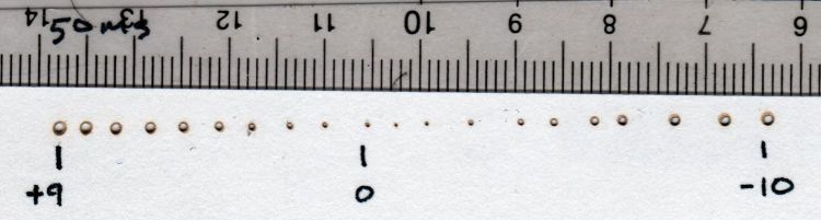
I ran a manual test firing 50 ms pulses into thin cardboard atop a 9+ mm (3/8 inch + protective papers) sheet of plastic (distance to lens increases to the right, the numbers are the nominal surface elevation relative to the autofocus level):
OMTech 60W laser beam test – Focus Check
The “0” pinhole may have happened near the actual focal point, but the true distance isn’t particularly accurate.
A closer look suggests the focal point sat 1 mm above the nominal zero:
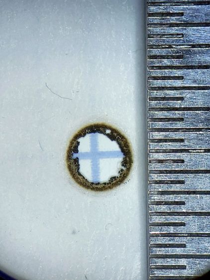
OMTech 60W laser – focus check – detail
In round numbers, the lens produces decent focus within ±1 mm of the focal point. The smallest hole is 0.3 mm, with the scorched ring bringing the mark to 0.4 mm, although the blast radius depends on the material and laser current setting.
The hole is slightly off-center because I hadn’t yet tweaked the red dot laser.
The hole came from two pulses, one at the autofocus level and another with the platform 10 mm lower. Comfortingly, the beam hit the same spot, with the slightly defocused beam chewing the rim a little larger, showing that the beam path is perpendicular to the platform motion.
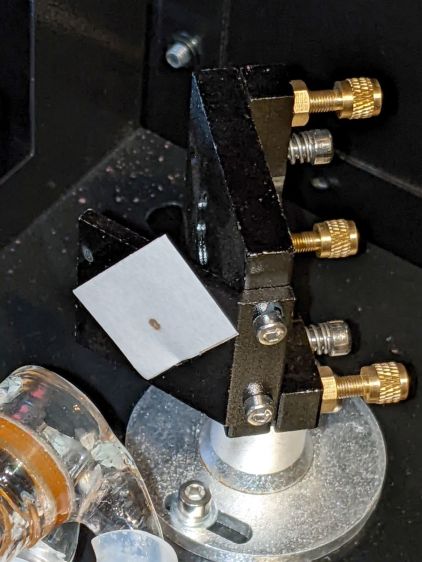
The canonical beam alignment target seems to involve tape stuck on the mirror bracket:
OMTech 60W laser beam test – tape target
With a full-power beam burned through it:
OMTech 60W laser beam test – mirror 1
The roll of “white masking tape” supplied by OMTech turned out to be knockoff tapeless sticky adhesive film. After sticking a length to the mirror bracket, the white backing tape peels right off, leaving the adhesive film stuck to the bracket. Well, my tapeless sticky roll was running low, so this roll won’t go to waste.
A laser cutter can make intricate paper doodads, so I conjured better targets from the Vasty Digital Deep:
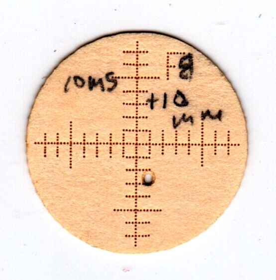
OMTech 60W laser – beam alignment – 2022-03-22
They’re burned into an ordinary manila file folder in “dot mode”: 2 ms pulses at 30% power separated by 0.25 mm. The 1 mm graticule locates the beam relative to the center, which is pretty close to the actual center of the opening, because the outer 17 mm cut fits neatly into the 17.5 mm hole. The label tells you where it goes and which line should point up.
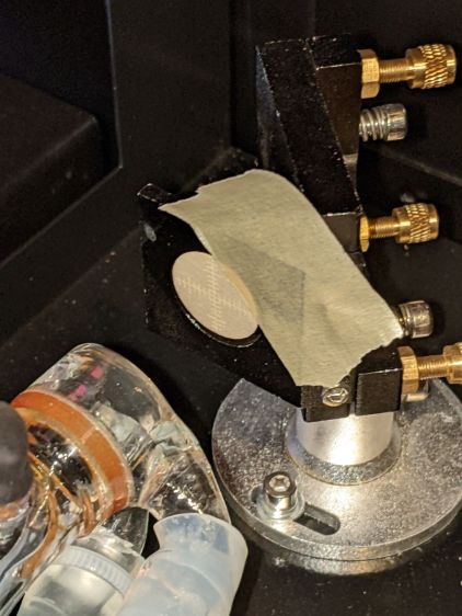
Your mileage will vary, but the general idea is to have a disk held in place by actual masking tape:
OMTech 60W laser beam test – mirror 1
Admittedly, orienting the graticule requires a bit of dexterity, but getting it pretty close is pretty easy.
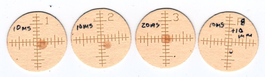
Set the laser to fire a single 10 ms pulse when you press the front-panel button, thereby toasting a spot at the most intense part of the beam:
OMTech 60W laser beam test – mirror 1 fired
Repeat to record the beam position at all three mirrors:
OMTech 60W laser beam test – mirror 3 fired
The focal point target serves to verify the focused beam size and its alignment with respect to the aiming laser spot:
OMTech 60W laser beam test – focus point
That target came from a scrap of cardboard while I was figuring out how to make the things.
All in all, OMTech did a pretty good job of aligning the beam, although the red laser dot needed a nudge. Now I have a record of where the beam was before I mess with clean the mirrors and lenses.
The honeycomb grid panel doesn’t have a perfectly flat surface, but the bench block kinda sorta averages things out:
OMTech platform alignment setup
I jogged the platform down until the nozzle just cleared the block, then measured the space at various spots across the grid. Somewhat to my surprise, it’s just about as good as you can expect:
OMTech platform alignment – 2022-03-17
You could argue that the left side is lower by half a millimeter.
The four stout single-start leadscrews moving the platform have a 4 mm lead (= pitch for single-start), driven by a belt with a 0.2 inch (!!) tooth spacing around 14 tooth sprockets, so moving the belt by one tooth produces 0.286 mm of vertical motion. I could loosen the belt and turn the left rear leadscrew one tooth to raise that corner, but not right now.
The laser lens has enough depth of field to cover a millimeter without too much spot size variation, unless you’re being very fussy. A quick focus check:
OMTech 60W laser – focus check – detail
The center hole happened pretty close to the lens focal point, with the adjacent holes 1 mm above / below that point. An accurate initial focus setting is obviously important, but varying by half a millimeter on either side seems survivable.