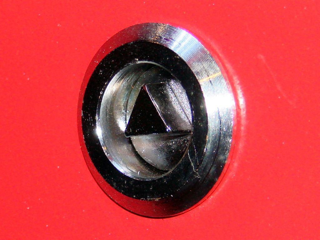
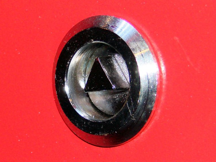
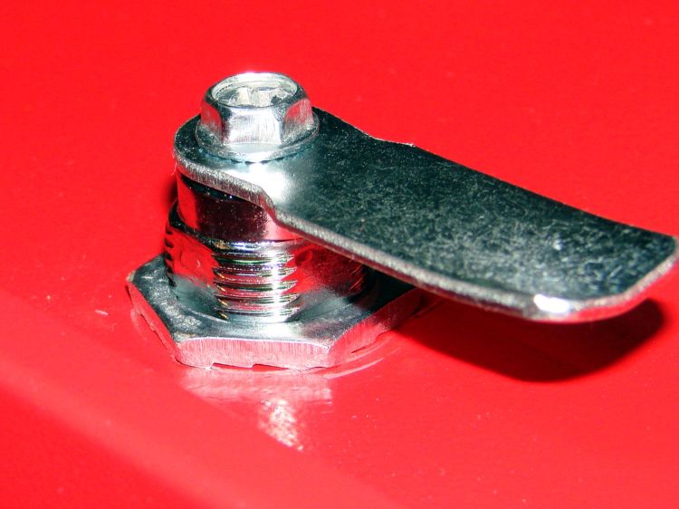
The OMTech laser cutter has six access hatches, each with one or two latches. These are not locks, although you do need a triangular “key” to turn the latch plug:
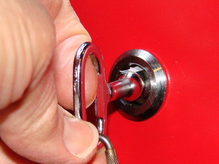
Being that type of guy, I want all the latches to have the same plug orientation when they’re closed, so that I can hold the key one way, poke it into any latch without thinking too hard, and have it fit onto the plug:
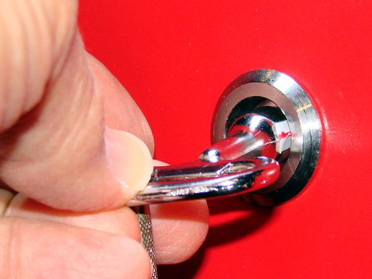
A quarter-turn clockwise (remember clocks with hands?) then releases the latch:
Inside the hatch, the closed position corresponds to a tongue capturing a flange around the cabinet opening (not shown):
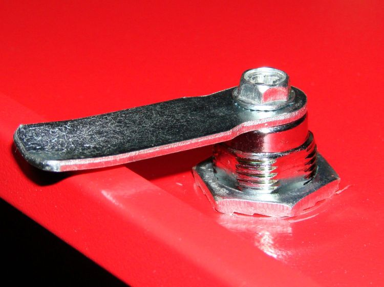
After the quarter-turn, the tongue releases the flange:
So, we’re not talking high security here.
As delivered, the plugs had more-or-less random orientations when they were closed and some required a counterclockwise quarter-turn to release.
It turns out the latches aren’t a complete unit that simply drops into a hole in the hatch:
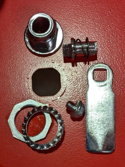
I sympathize with whoever must assemble ten handfuls of parts into ten latches on a production line and I also understand why orienting the plug wasn’t on that person’s to-do / QC checklist. I further understand why two cylinders lacked the big toothed washer under the nut; it’s not essential to the function and nobody will ever miss it.
The plug has a triangle on one end (for the key) and a square on the other (for the tongue), with one triangle point aligned to a side of the square:
To my way of thinking, that point must be upward, as shown in the first picture, when the latch is secured.
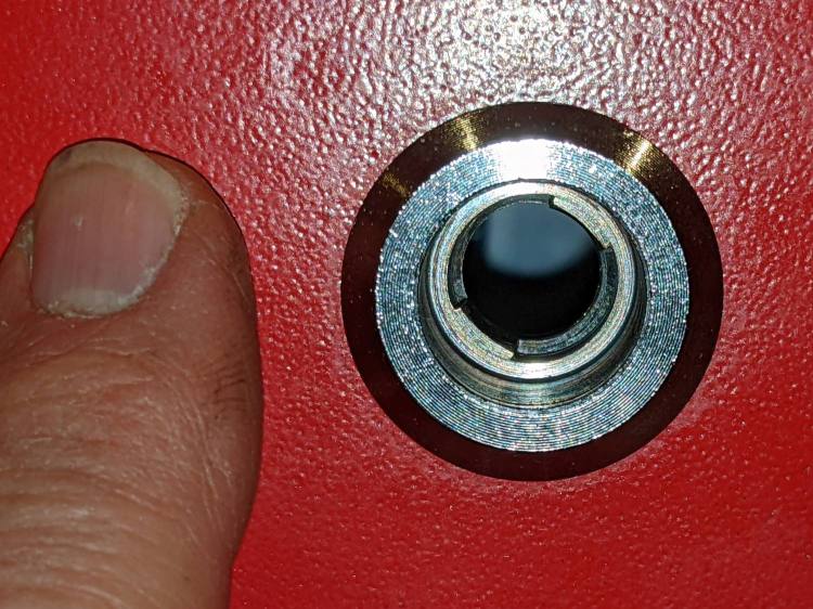
The cylinder can fit into the square(-ish) hatch hole in four possible ways, but its symmetry allows only two unique orientations. It must look like this in order to put that point upward when the plug is maximally counterclockwise (my finger is pointing upward):
So I devoted a pleasant half-hour to reducing the latch entropy.
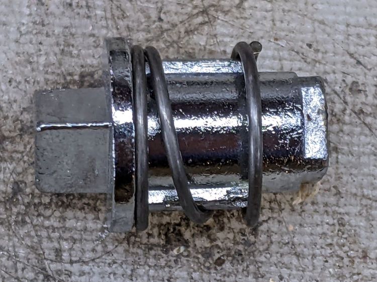
The screw attaching the tongue to the plug also controls the friction of that spring against the plug as you (well, I) turn it. All the screws now sport a dab of Loctite to ensure the tension remains mostly constant (at least for a while), as do the two large nuts lacking corresponding toothed washers.
The “key” has no marking to indicate its “point-up” orientation, so I stuck a snippet of label on one side, with a jaunty red highlight marking the point. Something better will surely occur to me, but it’s no longer in the critical path.