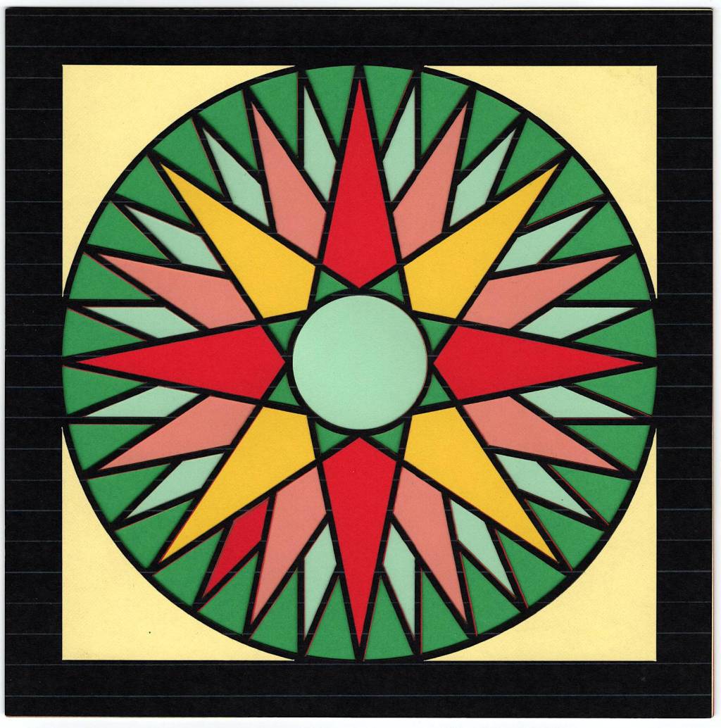
The Mariner’s Compass pattern on page 133 of Jinny Beyer’s The Quilter’s Album of Blocks and Borders:

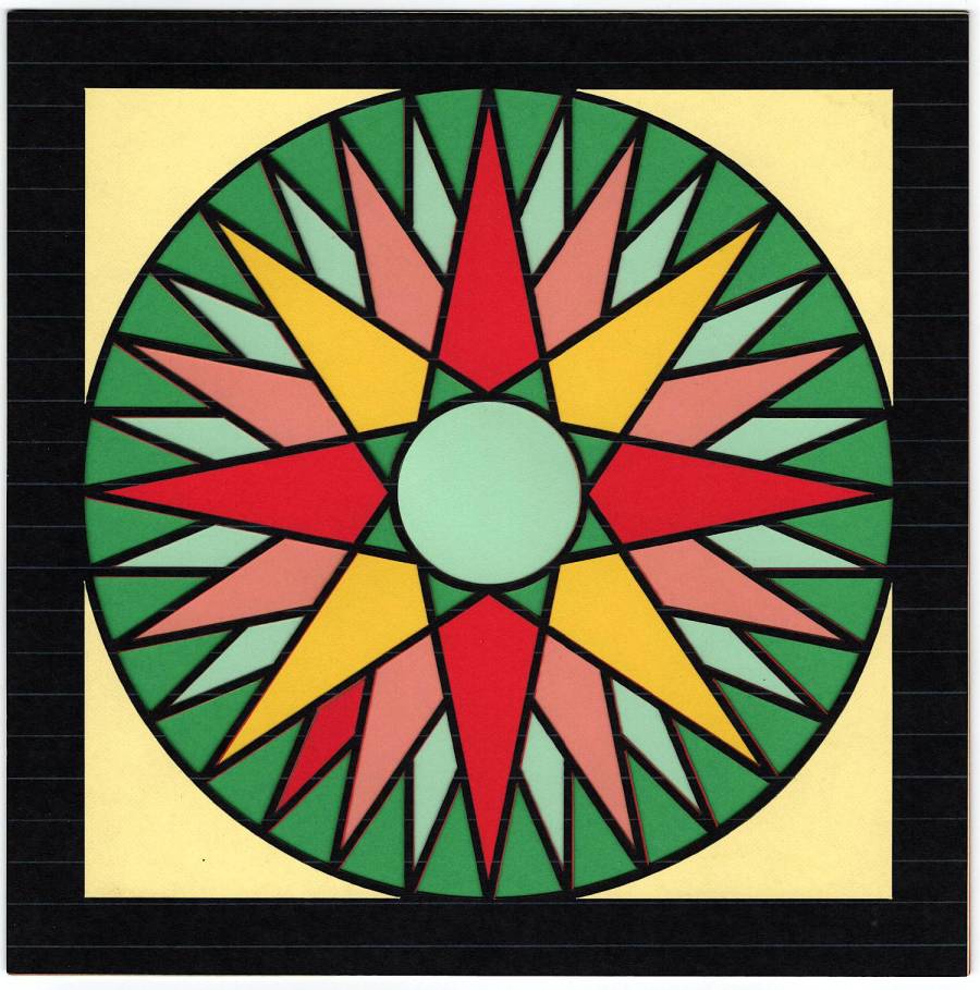
Becomes a laser-cut layered paper design:
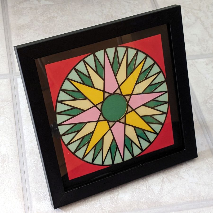
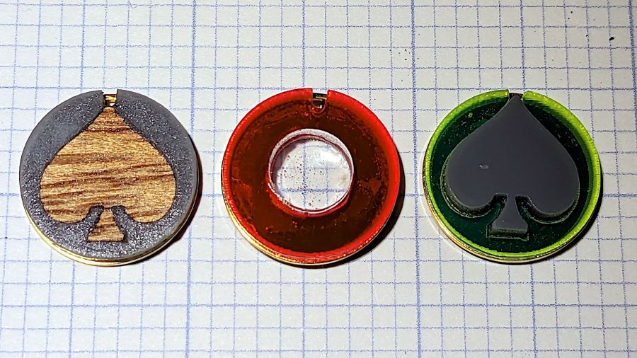
A face-on view with different colors:
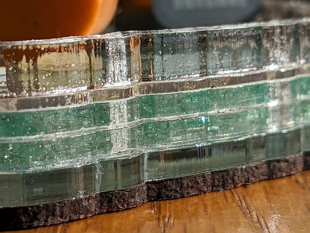
This seemed like an appropriate use for the stack (well, several stacks) of colored paper I’ve accumulated over the years.
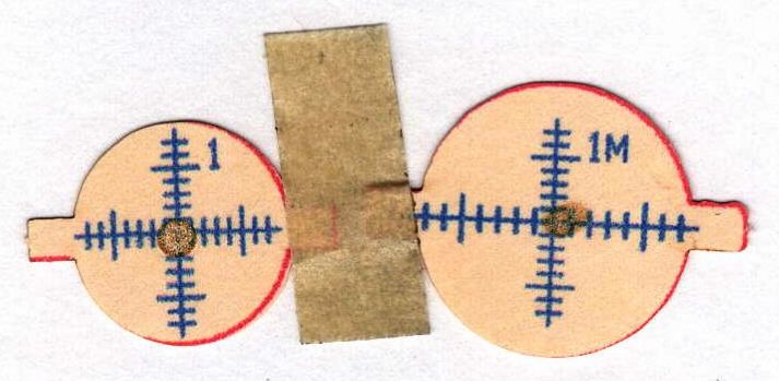
The illustration in the book is apparently a photograph of a quilt block Beyer put together, so I had to reverse-engineer the Platonic Ideal Block from the image:

Fortunately, after a bit of fiddling around, I could take advantage of the radial symmetry to duplicate most of the fundamental shapes, so producing the layout really wasn’t all that difficult:

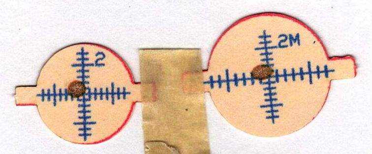
The blue tooling lines (upper left) run along the centers of what would be seams in a fabric block, with 2 mm circles defining the endpoints for ease in snapping the lines.
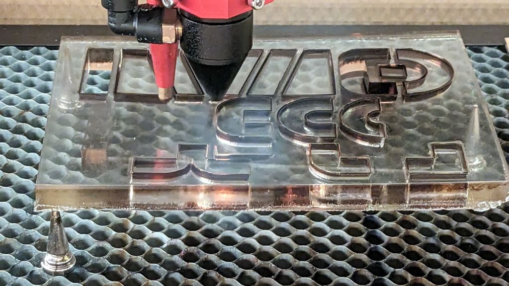
This being the first block I attempted, I did it all wrong. LightBurn can form the convex hull over a group of shapes, so I just selected pairs of circles, created the hull, and iterated for the minimal shapes required to generate the whole design. That produces the basic layout, but what you really want is the collection of shapes between those hulls that define the actual cutouts, which appears in the lower left image.
Don’t do it that way, as explained tomorrow with a different block.
With all the shapes in hand, you duplicate them for all the paper layers you need, removing the shapes corresponding to the color of each sheet. Sheets lower in the stack have fewer cutouts, with the pattern in the lower right being second from the bottom.
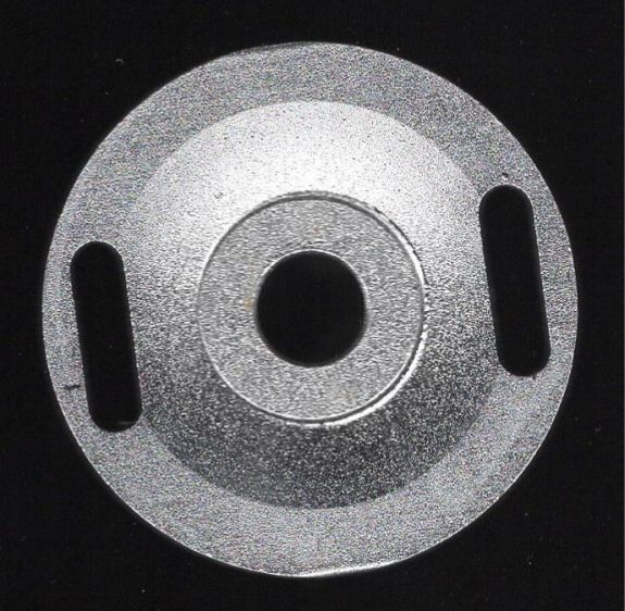
The four holes in the corners fit over rivnuts in a fixture aligning the sheets in a tidy stack:

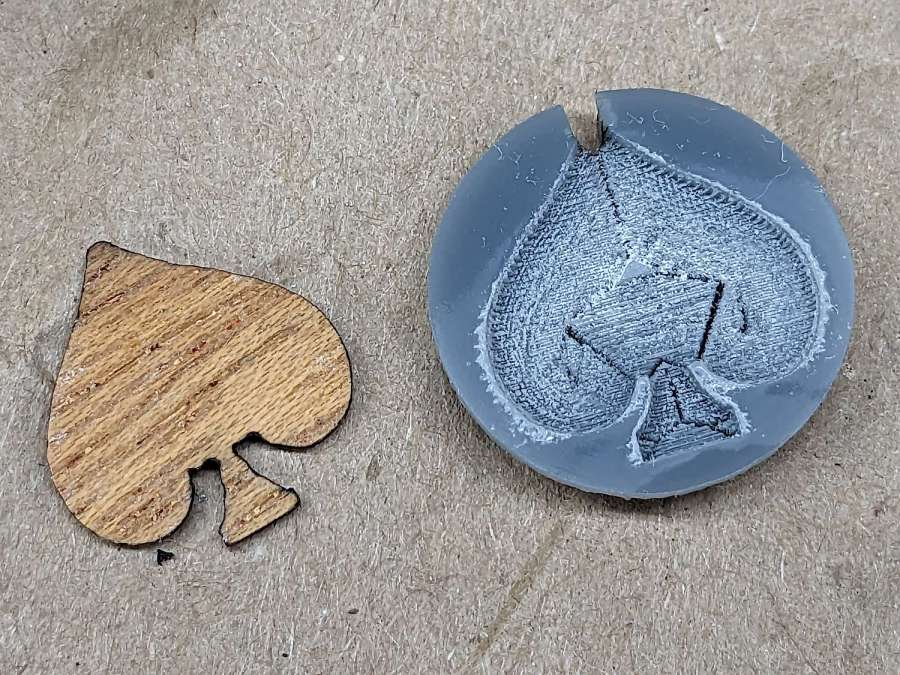
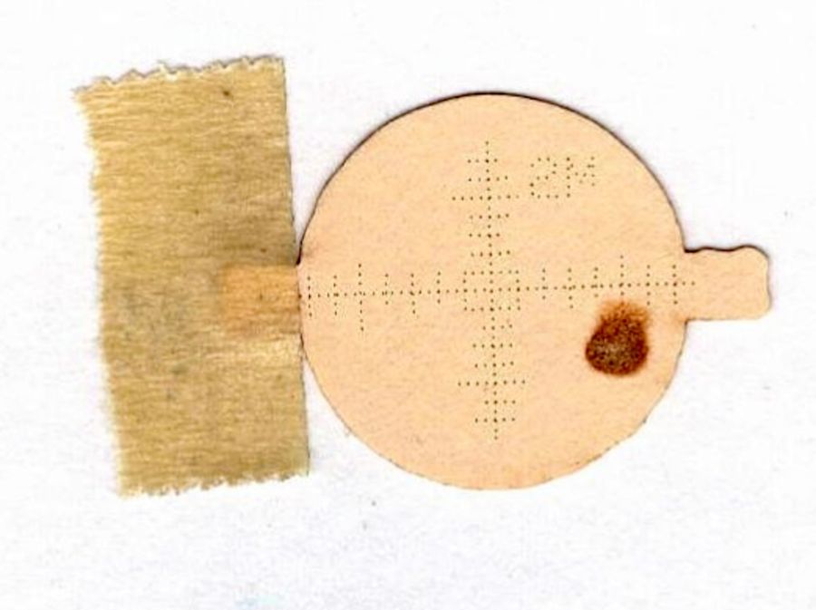
Yes, that’s a blooper sheet.
All in all, it’s easier than I expected to get nice results.