The Smell of Molten Projects in the Morning

Ed Nisley's Blog: Shop notes, electronics, firmware, machinery, 3D printing, laser cuttery, and curiosities. Contents: 100% human thinking, 0% AI slop.

Tag: Improvements

Making the world a better place, one piece at a time

  • Thing-O-Matic: Vent Fan and Charcoal Filter

    Fan filter and 5 V dummy load
    Fan filter and 5 V dummy load

    Hot ABS plastic gives off a characteristic stink odor smell aroma that’s hard on the nose and probably not particularly good for the lungs. Even in the basement, it seems like a Bad Idea to stink up the place, so I added an exhaust fan and charcoal filter to blot up the odor.

    The key step is to add the fan provided with the TOM (which they recommend you don’t use!): outside the box, oriented backwards, and running on +5 V instead of +12 V. The general concept: free up some precious space inside the box, shove the exhaust through a filter, and do it with a gentle breeze rather than a mighty blast.

    Although it’s not a part of this sub-project, the heatsink holds a 2 Ω 25 W resistor that serves as a 12.5 W dummy / minimum load on the +5 V supply to keep it within tolerance. Right now, the heatsink is just jammed between the screws, because I’m probably going to add a similar dummy load to the +12 V supply when I move to a stepper extruder.

    In case you’re hypersensitive to overheated resistors: the heatsink runs at 65 °C, the resistor at 75 °C, and the specs give a permissible dissipation of 20 W. You could work it out…

    Ersatz ATX connector
    Ersatz ATX connector

    The first step is to route the 4-pin ATX power connector (which popped off the big connector block plugged into the Motherboard) out the left-rear hole in the acrylic floor under the XY stage. I don’t have a mating connector, so I conjured up something from the same square pins as I used in the Extruder power supply modification and some wire harvested from a dead ATX supply. The black heatshrink tubing holds the four wires and their pins in the proper configuration. Obviously, you want matching colored wires, because the “connector” isn’t polarized!

    On the other end, a four-pin screw terminal block provides a convenient way to attach a variety of gadgetry. At last count, it serves the exhaust fan, +5 V dummy load, LED platform light, and a cooling fan. More details on those later…

    Terminal Block
    Terminal Block

    The fan frame required a small gouge to route the wire inward through the vent hole in the side of the TOM case:

    Fan frame modification
    Fan frame modification

    Four nuts secure the fan to the frame. Fortunately, the fan’s motor housing sits on the exhaust end, so the filter material rests against the hub support and spider. Here’s what the whole arrangement looks like, with the filters pried away from the fan.

    Fan and filter mounting
    Fan and filter mounting

    A trip to the local Big Box home warehouse produced a $10 20×25-inch activated charcoal air filter intended for a whole-house air conditioner. I now have a large plastic grid, a sheet of open-cell foam air filter, plus a generous supply of charcoal filter material. I cut a 4-3/4-inch strip from one side, chopped it into 4-3/4-inch squares (that’s 120 mm everywhere else in the world), trimmed off the corners, tucked two layers behind the TOM filter holder frame, and added four more nuts-and-washers.

    The spare filter material goes in a sealed plastic bag, because activated carbon has a limited lifetime when exposed to free air. That’s what it does for a living: adsorb smelly molecules from passing air!

    The final step is to close off all the TOM’s openings, thus restricting air flow through the case. This has the happy side effect of warming the build area and reducing drafts, both quite important in a wintery 50-ish °F basement. Taking pictures of clear acrylic sheet is essentially impossible, but you can see the front piece there and the paper seals around the filament spool there. I make no apology for the masking tape; after everything’s working, I’ll formalize the arrangements.

    Incidentally, don’t get too secure with the front window, because the ABP pokes through the opening to disgorge finished parts. In fact, the front of the ABP whacks the window when the nozzle reaches the back of the ABP, so you don’t want a mechanical latch holding the window closed.

    I’m thinking a magnetic latch is in order.

    There’s enough leakage around the windows to keep the fan happy, although it sucks the last one closed. Those four square cable holes in the acrylic sheet between the upper and lower chambers provide the only air channels, so the exhaust fan probably doesn’t compete with the ATX supply’s cooling fan.

    While the filter doesn’t kill off all the stink, the TOM is a much better companion now…

  • Thing-O-Matic: Platform Light

    Platform light overview
    Platform light overview

    The inside of a Thing-O-Matic gets pretty dark, particularly with the Lazy Susan spool parked on top, so I added a spot light to the Z stage.

    The alternative seems to be LED strip lighting all over the inside, but my Parts Heap doesn’t have any of those yet and it did have a 10 mm white LED. The thing runs at 100 mA, so a 15 Ω 1/2 W resistor (to a +5V tap), a few snippets of heat-shrink tubing, and a blob of hot-melt glue did the trick.

    Some sculpture armature wire that’s been kicking around for years holds the LED (wrap it around, add hot-melt glue) and doesn’t mind the occasional bump. I crimped the wire in a solderless connector and grabbed it in one of the Extruder Frame screws. It’s allegedly fatigue-proof, but it looks a lot like aluminum.

    A bit more detail, with a Kapton-and-graph-paper belt (about which, more later) on the ABP:

    Platform light detail
    Platform light detail
  • Thing-O-Matic: Improved Timing Belt Clamps

    The laser-cut plywood clamps holding the timing belts to the drive ribs slant diagonally across the rib + belt and secure one edge of the belt.

    Belt clamp before modification
    Belt clamp before modification

    While this certainly works, it offended my sensibilities and is probably why the instructions call for that low-profile bolt.

    Introducing the belt clamp to Mr Disk Sander provided just enough relief to clear the belt’s backing, while not making for a sloppy fit. In round numbers, if you barely trim off the plywood veneer it’ll be about right. Use an ordinary file if one of Mr Sander’s relatives doesn’t live in your shop.

    Modified belt clamp
    Modified belt clamp

    And then it works just like it should. If you were even fussier, you might chamfer the outer edges to allow the belt to lie flatter against the rib, but that’s in the nature of fine tuning. At least on my Thing-O-Matic, there’s plenty of air between a standard bolt head and the adjoining carrier rod.

    Modified belt clamp in place
    Modified belt clamp in place

    This is obviously not something you should dismantle your Thing-O-Matic for, but if you’re in the delightful position of facing that mountain of parts, this is perfect timing.

  • Thing-O-Matic: Cable Clampage

    The snarl of wires, cables, and filaments inside a Thing-O-Matic is a wonder to behold. A few cable clamps can tidy it up and reduce the chance that a loose wire will snag on a moving stage.

    It’s probably a Good Idea to keep the thermocouple cable out of the bundle with the stepper cable, but, other than that, a few clamps inside the body work fine:

    Cable clamp inside body
    Cable clamp inside body

    There’s another clamp inside the right-front corner that corrals the ABP cabling.

    Atop the body, a clamp keeps the Z axis cable and Extruder motor wires under control. This was before I added Powerpoles and the Safety Lamp into the DC motor cable.

    Cable clamp atop body
    Cable clamp atop body

    A little clamp immobilizes the thermocouple cable near the Thermal Core. The fat red wire across the top is the Thermal Core static drain and ground connection.

    Thermocouple cable clamp
    Thermocouple cable clamp

    These clamps have an adhesive backing, which means you don’t have to drill holes and lose screws under the bench, and it’s not the end of the world should you stick one in the wrong spot.

  • Thing-O-Matic: Rod End Cap Tweakage

    The Y axis rods seem to be a bit too long for the overall case size; they stuck out the better part of 2 mm.

    Y axis rod protrusion
    Y axis rod protrusion

    I applied a 3/8-inch Forstner bit to the inside of the rod end caps to make a slightly-too-deep recess, then shimmed the hole with some cardboard to make the answer come out right.

    Recessed Y-axis rod caps
    Recessed Y-axis rod caps

    The Z axis rods were just barely too long, but I did the same thing to those caps.

    The X axis rods were fine!

  • Thing-O-Matic: Nut Anchoring

    The next time you take your Thing-O-Matic apart, epoxy the damn nuts in place so you’re not going crazy trying to manipulate them.

    Inside the ends of the Y axis stage, which makes removing the X axis rod covers trivially easy:

    X axis rod cover nuts
    X axis rod cover nuts

    Inside the front and back body panels, which makes removing the Y axis rod covers trivially easy:

    Y axis rod cover nuts
    Y axis rod cover nuts

    That’s in addition to applying tape inside the panels at all the most-likely-to-be-removed T-nut locations, of course. I’m loathe to epoxy those nuts in place, but I could overcome that reluctance after bringing a few more of the things to heel under the bench…

  • Thing-O-Matic / MK5 Extruder: Protecting the Thermocouple

    The stock MK5 Extruder head assembly instructions suggest wrapping the thermocouple with Kapton tape before capturing it under the washer against the Thermal Core. Alas, as I’ve found, that doesn’t work well: the tape isn’t proof against mechanical forces applied to small objects and the thermocouple bead can punch through the tape to contact the Core.

    This isn’t a problem until one of the heating resistors blows out and shorts the +12 V supply to the Thermal Core. The only ground path is through the thermocouple, which leads to the MAX6675 thermocouple interface chip, which generally results in a dead Extruder Controller. The third picture in that thread is chilling, isn’t it?

    I cast my thermocouple into a brick of JB Industro Weld epoxy for both mechanical and electrical protection. The epoxy is rated for 500 °F (call it 260 °C), which is barely adequate for the job, but JB Weld is cheap & readily available. Note that this isn’t your really cheap garden-variety clear epoxy, which falls apart at much lower temperatures. That discussion suggests a higher-temperature epoxy from Omega, but I haven’t gone that route yet.

    Anyhow, I converted three credit-card-thickness sale coupons from Staples into a brick-shaped mold around the thermocouple. The middle card has a slot for the thermocouple wire, which means the bead is positioned in free space in the middle of the opening.

    Thermocouple positioned in mold
    Thermocouple positioned in mold

    A close-up of the thermocouple bead:

    Thermocouple positioned in mold - detail
    Thermocouple positioned in mold – detail

    I taped that assembly to another coupon, filled the mold with JB Weld, made sure everything was saturated, and gave it a day to cure. This view shows the brick after peeling off the top coupon, so you can see the cable slot:

    Removing thermocouple from mold
    Removing thermocouple from mold

    A bit of filing and general cleanup made it presentable:

    Finished thermocouple brick
    Finished thermocouple brick

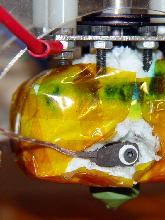
    A wrap of Kapton around the brick gives the Thermal Core washer something to grab onto:

    Thermocouple in place - ceramic insulation jacket
    Thermocouple in place – ceramic insulation jacket

    The brick could be much smaller without any penalty. There’s no issue with excessive thermal mass here, however, because the Core itself has a 10-minute time constant, so the thermocouple has plenty of time to tag along.

    The red wire in the upper-left corner connects the plate above the Thermal Core directly to the static drain ground point that leads to the ATX power supply case. In the event of a resistor failure that shorts the +12 V supply to the Thermal Core, the power supply should shut down. Whether that will actually happen, I cannot tell, but now a failed resistor won’t destroy the thermistor or the Extruder Controller.

    The ceramic wool insulation (from a lifetime supply of furnace chamber lining; it’s rated for direct oil burner flame impingement) may seem excessive, but I wanted measurements from a well-insulated Thermal Core at reduced power: 40 W seems to do the trick.

    However, the insulation on the bottom of the Core around the Nozzle tended to catch on the ABP’s silicone wiper. The next iteration used just the original MBI ceramic cloth insulation on the bottom, protected by Kapton tape, with ceramic wool around the rest of the Core. Much better!