
Having external indications for the laser cutter’s internal status signals seemed like a good idea and, rather than build the whole thing, I got a five-layer stack light:
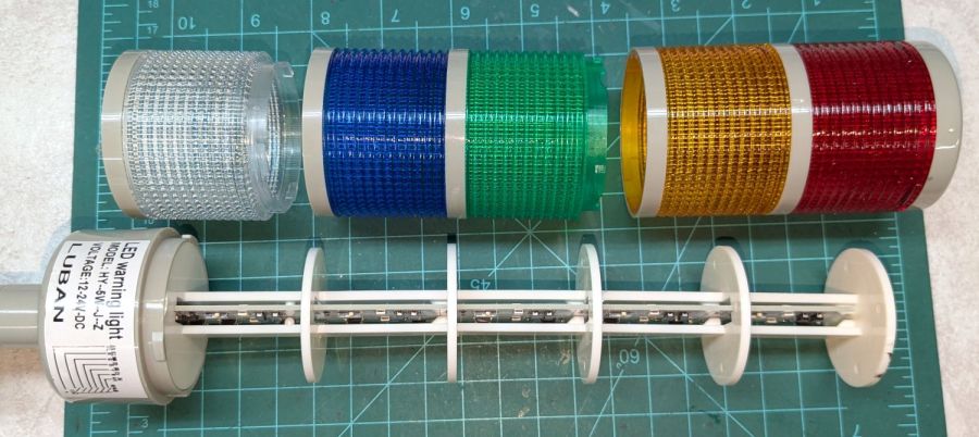
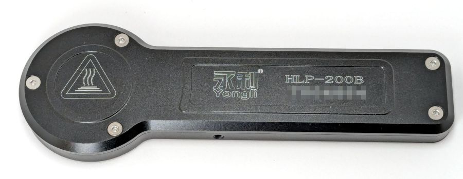
It arrives sans instructions, apart from the data plate / wiring diagram label on the housing, so the first puzzle involves taking it apart to see what’s inside. My motivation came from a tiny chip of blue plastic on the kitchen table where I’d opened the unpadded bag. Apparently, a mighty force had whacked the equally unpadded box with enough force to crack the blue lens, but I have no idea how the sliver escaped the still-assembled stack.
Anyhow, hold the blue/green lenses in one hand and twist the red/yellow lenses counterclockwise as seen looking at the cap over the red layer. Apply more force than you think appropriate and the latches will reluctantly give way. Do the same to adjacent layers all the way down, then glue the blue chip in place while contemplating other matters.
A switch on each layer selects either steady (the default and what I wanted) or blinking (too exciting for my needs). Reassemble in reverse order.
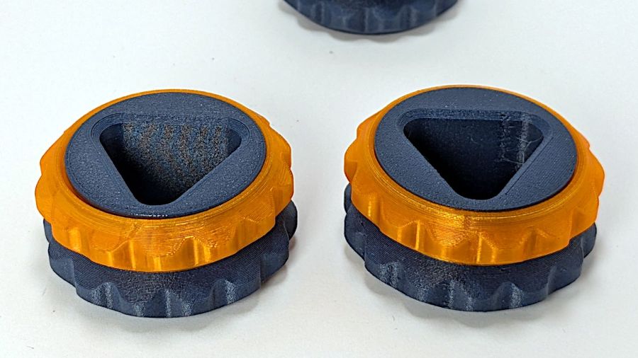
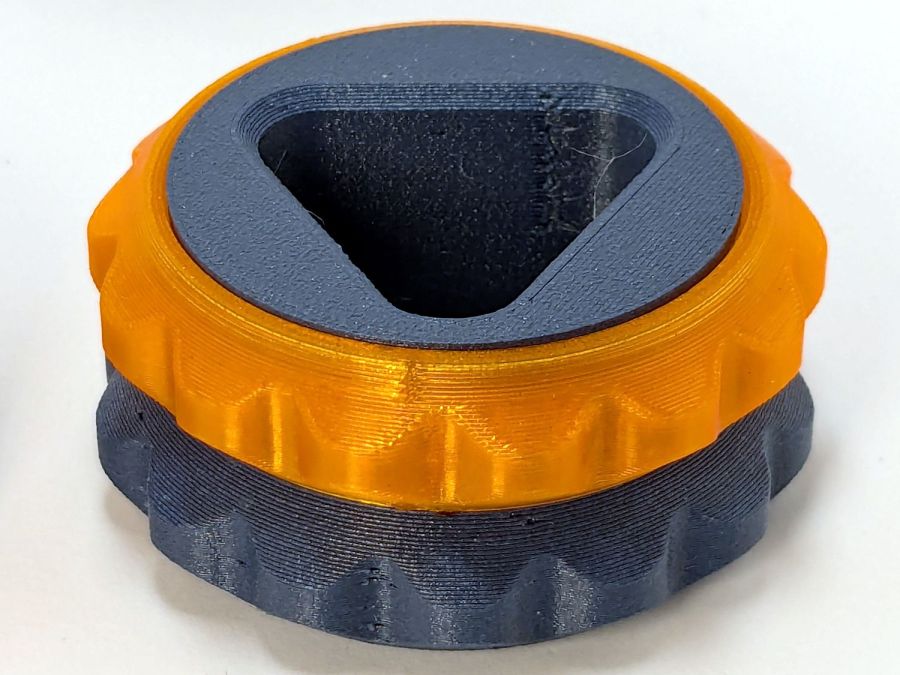
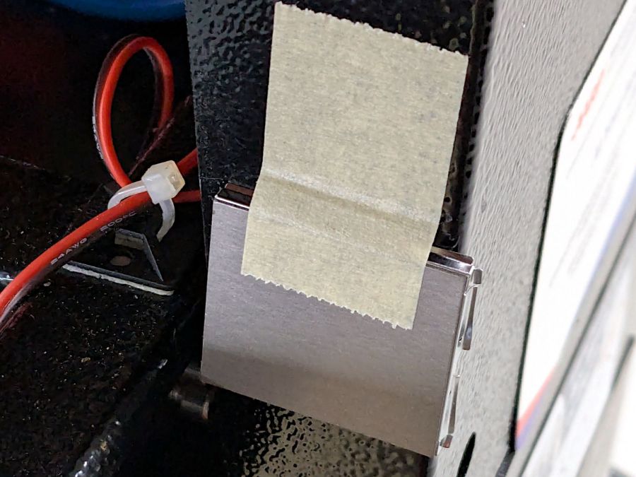
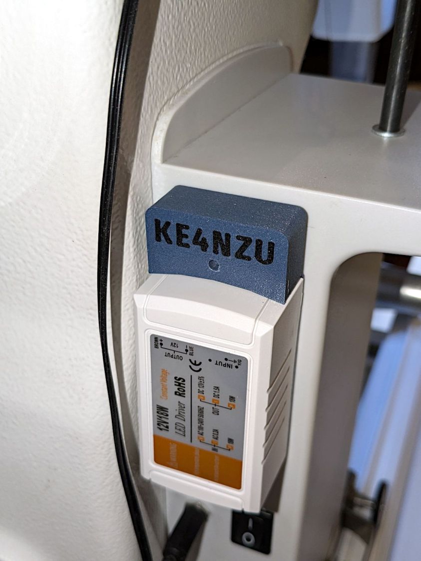
A Stack Light generally mounts on a production-line machine which might have a suitable cutout for exactly that purpose. I have no such machine and entirely too much clutter for a lamp, so I screwed it to a floor joist over the laser:

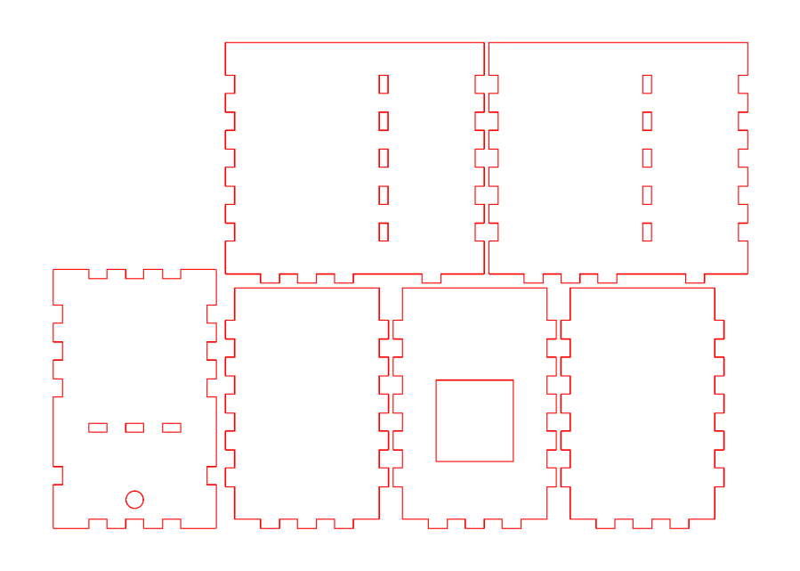
The tidy blue PETG-CF base started as a scan of the lamp’s base to serve as a dimension reference:

Import into LightBurn:
- Draw a 70 mm square centered on the workspace
- Round the corners until they match the 13 mm radius
- Draw one 5.6 mm circle at the origin
- Move the circle 52/2 mm left-and-down
- Turn it into a 4 element array on 52 mm centers
- Verify everything matches the image
- Export as SVG
Import into Inkscape:
- Put the perimeter on one layer
- Put the four holes on another
- Center around an alignment mark at a known coordinate
- Save as an Inkscape SVG
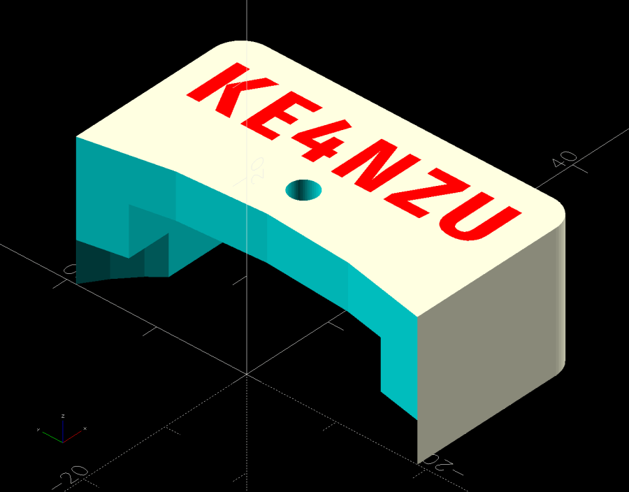
Import into OpenSCAD, extrude into a solid model, and punch the holes:
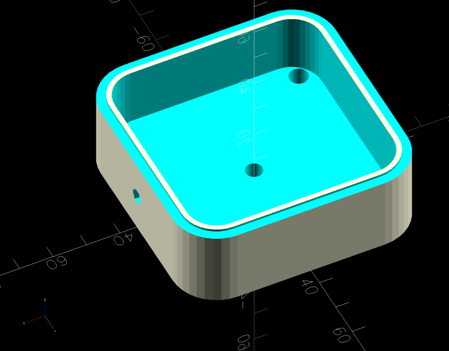
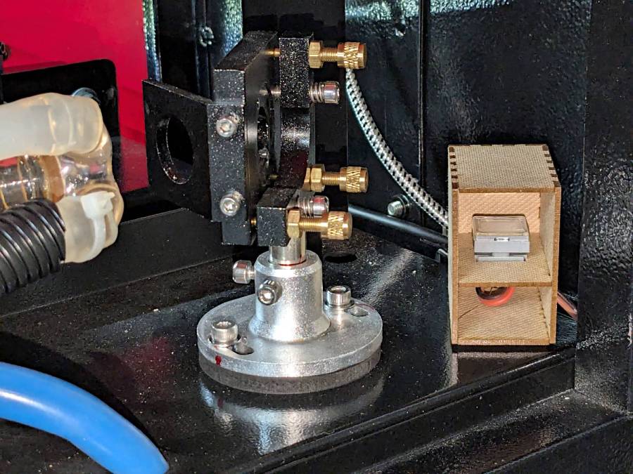
The lip around the inner edge aligns the lamp base.
If I ever make another one, I’ll add pillars in the corners to put the threaded brass inserts close to the top for 10 mm screws instead of the awkward 30 mm screws in this one. More than a single screw hole in the bottom would align it on whatever you’re indicating.
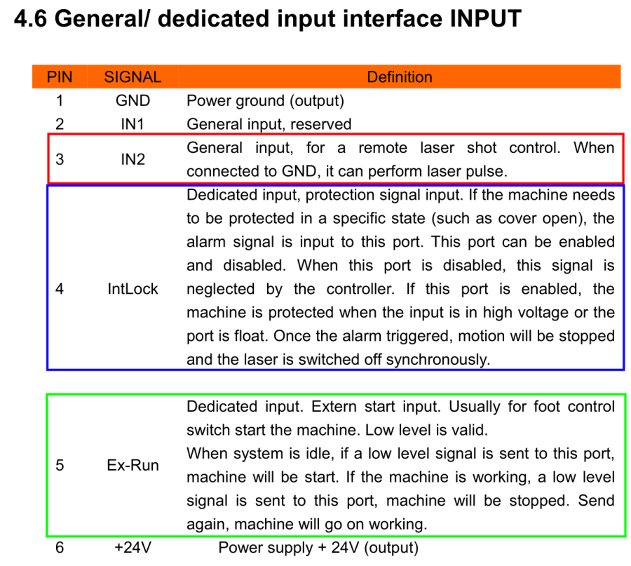
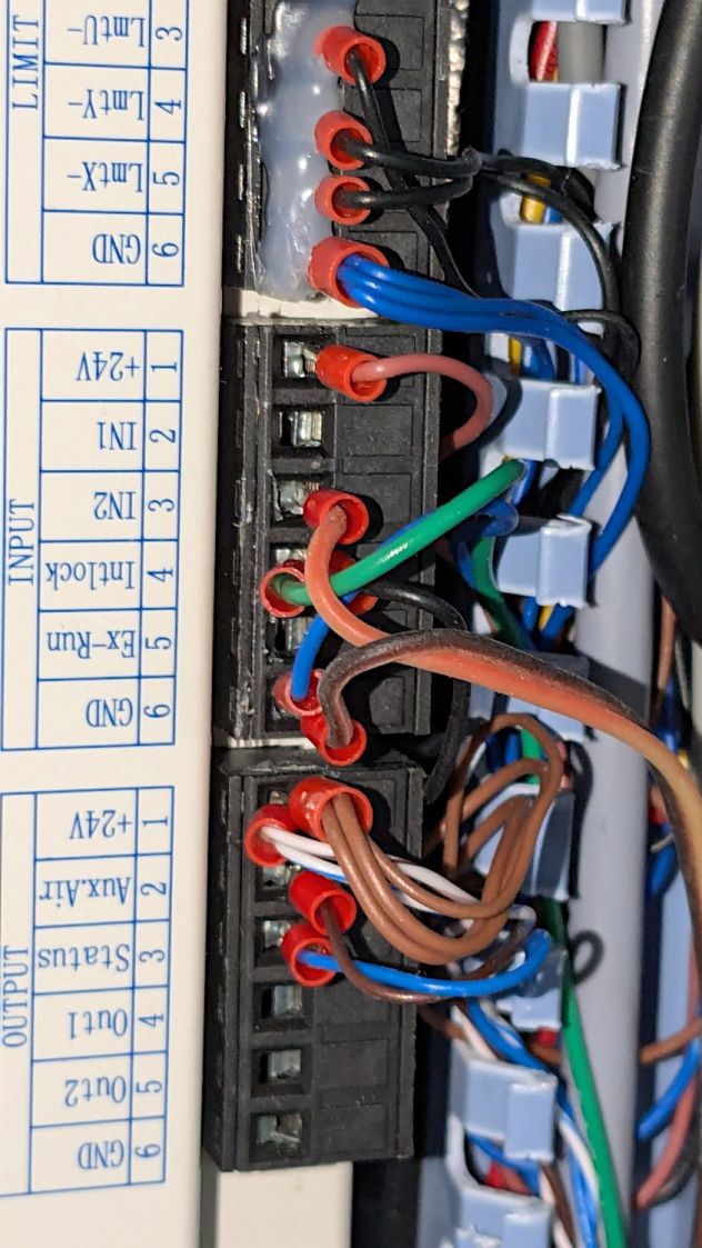
Now, to wire the thing up …
The OpenSCAD source code as a GitHub Gist:
| // Stack Light mount | |
| // Ed Nisley – KE4ZNU | |
| // 2025-01-03 | |
| include <BOSL2/std.scad> | |
| /* [Hidden] */ | |
| ID = 0; | |
| OD = 1; | |
| LENGTH = 2; | |
| BaseCenter = [100,100,0]; | |
| Base = [70,70]; // nominal, for figuring holes | |
| Insert = [4.9,5.9,6.0]; | |
| PlateThick = Insert[LENGTH]; | |
| HolderTall = 24.0; | |
| WallThick = 2.7; // outer wall of light base | |
| LipThick = 1.5; // alignment lip inside light base | |
| LipTall = 0.75; | |
| CableOD = 5.0; | |
| Protrusion = 0.1; | |
| difference() { | |
| translate(-BaseCenter) | |
| linear_extrude(height=HolderTall + LipTall) | |
| import("Stack Light – base layout.svg",layer="Base Perimeter"); | |
| up(Insert[LENGTH]) | |
| translate(-BaseCenter) | |
| linear_extrude(height=HolderTall – LipTall) | |
| offset(delta=-(WallThick + LipThick)) | |
| import("Stack Light – base layout.svg",layer="Base Perimeter"); | |
| up(HolderTall) | |
| linear_extrude(height=HolderTall,convexity=5) | |
| translate(-BaseCenter) | |
| difference() { | |
| offset(delta=WallThick) // avoid glitches on perimeter edge | |
| import("Stack Light – base layout.svg",layer="Base Perimeter"); | |
| offset(delta=-WallThick) | |
| import("Stack Light – base layout.svg",layer="Base Perimeter"); | |
| } | |
| down(Protrusion) | |
| translate(-BaseCenter) | |
| linear_extrude(height=2*HolderTall,convexity=5) | |
| import("Stack Light – base layout.svg",layer="Base Holes"); | |
| up(HolderTall/2) | |
| yrot(90) zrot(180/6) | |
| cylinder(d=CableOD,h=Base.x,$fn=6); | |
| } | |


