Ed Nisley's Blog: Shop notes, electronics, firmware, machinery, 3D printing, laser cuttery, and curiosities. Contents: 100% human thinking, 0% AI slop.
Turns out that the anonymous parallel port breakout board isn’t compatible with an optoisolated stepper driver: each output has a 1 kΩ series resistor that limits the current well below the driver optocoupler’s expectations. The driver has an internal 300 Ω resistor on each input, too, which doesn’t help in this situation.
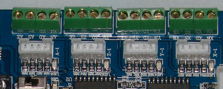
A detailed look at the resistors lined up in front of the connectors:
Anonymous parallel breakout board – series resistors
The breakout board would work fine with non-isolated drivers, like the Pololu breakout boards, so it’s not really at fault. The fact that there’s no doc anywhere to be found means you (well, I) couldn’t discover this without buying it first, but … I suppose it’ll come in handy for something.
One could short across the resistors, but I intended to use this board for the initial bringup and all that soldering defeats the purpose.
Parallel port breakout boards of this ilk run about $14, complete with cable, on eBay:
5 axis parallel port breakout board
The PCB has no part number and the inferred URL isn’t productive. The “driver CD” accompanying it has doc for every possible board the vendor might sell and, absent a part number, the file names aren’t helpful. An exhaustive search suggests it corresponds to the HY-JK02-M 5-axis interface board manual.doc file.
Despite any implication to the contrary, the board does not have optoisolators between the parallel port pins and the outside world. The stepper driver bricks should, but the input signals from limit switches and suchlike connect directly to the guts of your PC.
This overview (from the manual) shows the physical pin layout (clicky for more dots) and reveals the hidden silkscreen legend:
HY-JK02-M Breakout Board – overview
It looks like the board I got added a spindle relay driver transistor, plus a few resistors over by the manual control connector on the right.
Notice that the fourth terminal on each axis is GND, not the positive supply required for the optoisolators on the 2M415-oid driver bricks, which means you can’t just run a section of ribbon cable from the breakout board to the brick. You’ll need a separate +5 V (or whatever) power supply wire for each brick, with a common return to the system ground for this board. Those terminals are firmly bonded to the top and bottom ground planes on the board, so there’s no practical way to re-route them.
The small switch in the upper left, just to the right of the parallel port connector, selects +5 V power from the USB port (which has no data lines) or the power connector in the lower left. The LED near the switch won’t light up until you have both the parallel port cable and the USB cable plugged in.
The doc includes a timing diagram with no numeric values. I established that it can’t keep up with a 500 kHz pulse train and seems content at 100 kHz, but that’s conjecture. Setting the timing to match whatever the stepper driver bricks prefer will probably work. The diagram suggests the setup and hold times for direction changes are whatever you use for the minimum time between step pulses.
This shows the functional labels:
HY-JK02-M Breakout Board – function labels
The parallel port connector output pins, sorted by function:
Pin
9
1
2
14
16
3
7
8
6
5
4
17
Function
Spindle
motor
Enabled
X step
X dir
Y step
Y dir
Z step
Z dir
A step
A dir
B step
B dir
The parallel port connector input functions, sorted by pin:
X -Limit
Y- Limit
Z- Limit
A- Limit
Emerg Stop
10
11
12
13
15
The table uses Chinese for Pin 15: 急停.
It’s not clear whether the pins on the manual control connector are inputs or outputs, nor what the three separate Enabled lines do:
P1
P2
P3
P4
P5
P6
P7
P8
P9
P10
P11
P12
P13
P14
P15
B step
B dir
A dir
Z step
Y step
X step
X dir
Enabled
5V/VDD
5V/GND
A step
Z dir
Y dir
Enabled
Enabled
The three white connectors in the middle drive an LED readout board that’s probably most useful as a DRO for CNC-converted manual mills using the pendant for positioning.
The small white connectors duplicate the functions of the green screw terminals. They’re probably useful in a small machine that I’m not building.
This isn’t the board I intend to use in the final setup, because I need far more I/O pins, but it’ll serve for the short term.
Collected from various spots around the Web, including evanescent eBay listings, and reformatted to make sense, these specs describe the 2M415 stepper driver: a smaller sibling of the 2M542 family.
Blurb
+15 to 40VDC Supply Voltage
H-Bridge, 2 Phase Bi-polar Micro-stepping Drive
Suitable for 2-phase, 4, 6 and 8 leads step motors, with Nema size 16 to 23
Output current selectable from 0.21 ~ 1.5A peak
Compact credit card size package
Optically isolated single ended TTL inputs for Pulse, Direction and Enable signal inputs
Selectable resolutions up to 12800 steps
Over Voltage, Coil to Coil and Coil to Ground short circuit protection.
Electrical specs
Parameters
Min
Typ
Max
Unit
Output Current (Peak)
0.21
–
1.5
Amp
Supply voltage
15
36
40
VDC
Logic Input Current
7
10
16
mA
Pulse input frequency
0
–
200
KHz
Low Level Time
2.5
µsec
Mechanical specs
Cooling
Natural Cooling or Forced Convection
Space
Avoid dust, oil, frost and corrosive gases
Ambient Temp
0 °C – 50 °C
Humidity
40 – 80 %RH
Vibration
5.9 m/s² Max
Storage Temp.
-10 °C – 80 °C
Weight
Approx. 150 gram
Dimensions
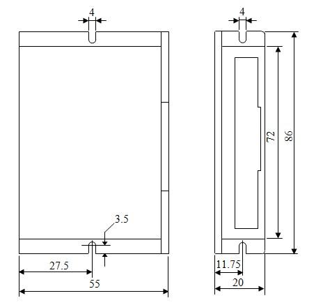
2M415 Footprint
Wiring diagram
2M415 Wiring
Notice that the driver requires a positive voltage for the optoisolators.
Of course, the box from halfway around the planet contained HB-415M drivers. Should you go looking with the usual keywords, you’ll find that HB-number turns up mostly “House Bill number” citations from various state legislatures. Popping the top off the drive reveals www.sikesai.com, which eventually produces a description and PDF datasheet for the driver. It turns out to be an “Ultra Low Noise” driver, whatever that means, with reasonably standard specifications that correspond more-or-less to the 2M415 drivers I thought I was getting.
Winding a slit ferrite toroid poses no challenge, so putting 25 turns of 26 AWG wire on it didn’t take long at all:
F50-61 toroid – 25 turns 26 AWG
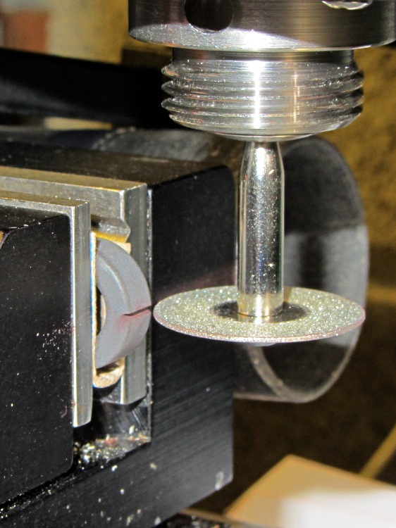
However, a ferrite toroid doesn’t take kindly to being dropped and I figured that a slit toroid would crack under a stern look, so I decided to wrap some armor around it. A small squeeze bottle offered a cap just slightly larger than the winding, so I used that slitting saw to cut off a suitable ring. The first step was to grab it in the 3 jaw chuck and align its axis parallel to the spindle:
Aligning bottle cap in 3-jaw chuck
I wanted to cut off a slightly taller ring, but the clamping screw on the saw arbor just barely cleared the chuck for a 5 mm ring. I jogged around the chuck jaws to cut two slits in the cap that eventually joined near the back:
Slicing ring from bottle cap
That was about 1000 rpm, no coolant, and slow feed, but also a totally non-critical cut in plastic.
I put a snippet of foam rubber in the slot, put the ring on a Kapton-covered build platform from the Thing-O-Matic, filled it with hot-melt glue, gooshed the toroid in place, and waited for cooling. Trimming and cleaning out the slit produced a hideously ugly, but (I hope) much more durable assembly:
Slit ferrite toroid – with armor
I’m reasonably sure I didn’t crack the ferrite while cleaning out the slit; that hot-melt glue is tenaciously gummy stuff!
The object of the game: cut a slit into a ferrite toroid that will accommodate a Hall effect sensor. Those doodles showed that an FT50 (half-inch OD) toroid would be about right for the cheap AH49/EH49 Hall effect sensors on hand and those doodles shows that the permeability of the ferrite mix doesn’t make much difference. Not being quite sure how this would work out, I figured I’d start with the simplest possible setup and complexicate things until it worked…
A fold of cereal box cardboard cushioned the brittle ferrite in the Sherline’s clamp and the vacuum hose in the background collects airborne grit. I touched off X=Y=Z=0 with the wheel at the center of the toroid’s equator:
Slitting ferrite toroid – first pass
The first pass went swimmingly, with the diamond wheel far more concentric than I expected, using manual jogging along a 0.5 mm deep cut. The wheel is slightly over 0.5 mm thick, measured on the grit, and showed no sign of strain on a 1 mm deep cut at 100 mm/min, so I used manual CNC to run the wheel back and forth along the cut.
After clearing the slot, I moved the wheel upward to + 0.5 mm, repeated the passes with a 1.5 mm depth of cut, then did the same at -0.5 mm. The end result was a nice slot with parallel sides:
Slitting ferrite toroid – complete
The actual gap measured 1.72 mm, not the 1.5 I wanted, which means the flux density will be lower than the previous calculations predict. Assuming the Z axis backlash compensation works as it should, then the kerf is 0.72 mm. Of course, that also assumes the arbor runs true and the wheel cuts symmetrically, neither of which I’d put (or, heck, have put) a lot of money behind. On the other paw, the sensors are 1.5 mm thick (just under the datasheet’s 1.6 mm spec), so +0.1 mm clearance on each side works a whole lot better for me than, say, -0.1 mm.
All in all, there was no excitement, no muss, no fuss, no chipping, no breakage:
Being in the market for some more-or-less industrial stepper driver bricks, here’s a summary of what’s currently available on eBay from the usual vendors, copied-and-pasted directly from the descriptions with some fluff removed:
M542 Stepper Driver Board Controller
Supply voltage from 20V DC to 50V DC
Output current from 1.0A to 4.5A
Self-adjustment technology, full to half current self-adjustment when motors from work to standstill via switching off SW4
Pure-sinusoidal current control technology
Pulse input frequency up to 300 KHz
TTL compatible and optically isolated input
Automatic half-current reduction as long as switching off SW4 when motors stop
16 selectable resolutions in decimal and binary, up to 51,200 steps/rev
Suitable for 2-phase and 4-phase motors
Support PUL/DIR and CW/CCW modes
Short-voltage, over-voltage, over-current and short-circuit protection, protect the PC, motors, driver etc from being damaged
M542H Stepper Driver Board Controller
Supply voltage from 20V DC to 100V DC
Output current from 1.0A to 4.5A
Self-adjustment technology, full to half current self-adjustment when motors from work to standstill via switching off SW4
Pure-sinusoidal current control technology
Pulse input frequency up to 300 KHz
TTL compatible and optically isolated input
Automatic half-current reduction as long as switching off SW4 when motors stop
16 selectable resolutions in decimal and binary, up to 51,200 steps/rev
Suitable for 2-phase and 4-phase motors
Support PUL/DIR and CW/CCW modes
Short-voltage, over-voltage, over-current and short-circuit protection, protect the PC, motors, driver etc from being damaged
2M542 Stepper Driver Board Controller
Suitable for 2-phase hybrid stepper motors (Outer diameter: 57,86mm)
H bridge bipolar constant phase flow subdivision driver
In round numbers, the M542 seems to be the basic driver for NEMA 17 / 23 /34 steppers. Remember that current isn’t proportional to frame size.
The M542H has a higher voltage limit that may be more useful with larger / multiple-stack motors; higher voltage = higher di/dt for a given inductance = same di/dt for higher inductance.
The 2M542 seems to be slightly different from both of its siblings: higher minimum voltage, slightly lower maximum current, slower step frequency. Many of the listings apply both M542 and 2M542 to the same hardware in the same listing, so it’s not clear what you’d get in the box. Ask first, trust-but-verify?
The MA860H seems appropriate for NEMA 34 / 42 and up , due to the much higher minimum current.
The 2M420 seems to be intended for NEMA 17 /23 class steppers. It’s not available from nearly as many suppliers.
The 2M982 looks like another NEMA 34 /42 and up driver.
The DM1182 seems strictly from industrial, but if you don’t know what you need, it’s a do-it-all killer.
As with all eBay listings, the picture need not match the description and neither may match what actually arrives in the box from halfway around the planet.
With the Bash script and OpenSCAD source in hand, here’s how you go about producing a grayscale image that works as the height map file to produce a cookie press and matching cookie cutter.
The Big Picture description: the grayscale height map image looks a lot like a photo of the final cookie on a plate in front of you. The darkest regions mark the thinnest parts of the cookie: black lines emboss deep trenches. Gray regions denote thicker sections and very light gray will be thickest. Because image files are rectangular, a pure white area surrounds the region that will become the cookie press and acts as a mask to remove the rectangular border.
If you start by hand-drawing the shape of the cookie press at full size inside a 5 inch square (chosen to match the 3D printer’s build platform and in inches because that’s how it got measured; it’s not my printer) with a 1.5 or 2 mm black marker, then the marker lines will be just about exactly the right width to ensure good plastic fill (for a printer producing a 0.5 mm thread width, anyway) and printable walls. You can scale the drawing for smaller (my Thing-O-Matic) or larger (M2, Series One) platforms, but the thread width and minimum wall thickness do not scale: a tiny 1 inch push mold must still have 2 mm walls.
The workflow looks like this:
Draw cookie press lines at full scale with fat black marker on white paper
Scan a 5×5 inch (127×127 mm) square around the image at 300-ish dpi → 1500×1500 pixel image
Convert a full-color scan to grayscale now (better to scan in grayscale)
Resize image to 317×317 pixel, optionally set 2.5 pixel/mm = 63.5 dpi for proper display size
Set color levels to blow out the contrast; auto probably works fine
Threshold to reduce to just two colors: 0% = black and 100% = white
Clean up the image: remove specks and single-pixel bumps, fill small gaps
Some sample images to show what happens along the way…
A hand-drawn image, derived from The Original Tux by crudely tracing the outline with a fat Sharpie, including some areas outside the box for pedagogic purposes:
TuxTrace – raw scan
The interior edge of the black box is exactly 5×5 inches. I created a 5×5 inch blank white image at 300 dpi, enlarged the canvas to 5.2×5.2 inches with the blank white image centered in the middle, set a black background, flattened the image to fill the border, and printed it out. That produces a piece of blank paper with a black square suitable for full-scale drawing.
It does not, however, confer any artistic eptitude whatsoever, so for this drawing I imported one of the Tux drawings, isolated the edges with one of The GIMP’s edge detectors, and traced over the thin lines with the aforementioned fat Sharpie. You can draw whatever you want, however you want it. If you already have an image file, you need not print it out and scan it back in; just resize it appropriately.
Pro tip: Ensuring that the drawing doesn’t touch the black square will greatly simplify the next half hour of your life.
A note on Sharpies. I used a Fine Point Marker, which is much fatter than a Fine Point Pen. The whole, uh, point is to produce a line about 2 mm wide that will become an actual plastic wall; you can’t print anything much finer than that.
A note on blackness. There’s no requirement for any black lines whatsoever. For most cookie presses, however, you want distinct walls that emboss lines into the dough, which is what the black lines will do. If you want to mold a cookie (or anything else, like a butter pat), you can produce a gently curved push mold by using only grayscale areas. For example, a circular area with a radial fill going from very light gray on the exterior to very dark gray in the center will produce a round cookie with a conical dent in the middle.
Given a drawn image, scan the area just inside the black square at 300 dpi to produce a nominally 1500×1500 pixel image, then resize it to 317×317 pixel at 63.5 dpi:
TuxTrace – crop resize
The magic number 317 comes from not wanting OpenSCAD to fall over dead after chewing on a larger image for an hour or two. Given the restriction to maybe 330×330 pixels, max, I picked a nice round 2.5 pixel/mm scaling factor that converts a 5 inch = 127 mm distance into 317 pixels:
317 pixel = 127 mm x 2.5 pixel/mm
The magic number 63.5 comes from wanting the image to print (on paper) and display (on screen) at the proper size:
5 inch = 317 pixel / 63.5 pixel/inch
Given a properly sized image, blow out the contrast so the background is mostly white and the lines are mostly black. This gets rid of background cruft:
TuxTrace – color levels
Then apply a threshold to get rid of all the gray levels. The threshold level determines the line width (the edges shade from black to gray to white), so you can tune for best width. The result doesn’t look much different than the blown contrast version, but the lines will become thinner and more jagged. Remember that you want the lines to be at least three pixels wide:
TuxTrace – threshold
Do whatever cleanup is required; eliminate single-pixel bunps and dents, fatten (or, rarely, thin) lines as needed. If you draw with a 3 pixel wide pen, the line will print just over 1 mm wide, which is about the thinnest possible wall and may encounter problems at corners. Use pure 0% black and pure 100% white.
If you possess powerful art-fu, you can draw that kind of image directly in the graphics program. Those of us with weak art-fu must rescale a found image of some sort. Should you draw a new image or rescale an old one, then:
Start with a 317×317 pixel grayscale canvas in 100% white
Draw lines with a 3 pixel (probably a square) 0% black pen
Now you have a clean black and white image of the cookie press lines; it’s still a grayscale image, but using only two colors.
Use color levels to reduce the white to about 95% gray; this avoids interior islands
Bucket-fill the exterior with 100% white (interior remains 95%): no anti-aliasing or blending
Fill interior regions with grays to set cookie press depths: dark = low, light = high, no 100% white, no anti-aliasing
Save as PNG to avoid compression artifacts
By reducing the overall white level to 95%, you get rid of all that pure white in the whole interior. Remember that pure white marks the area outside of the press, so any white inside the press will produce bizarre islands. You could pour 95% white into all the interior areas, but if you miss one, you have an island.
Having reduced all the whites, pouring pure 100% white around the press restores the exterior mask color. Turn off the anti-aliasing / blending / feathering options, because you want crisp edges rather than nice-looking gray transitions.
If all you want is a press with lines, you’re done. Save the image and proceed to make the cutter & press.
If you want a press that produces a cookie with different thicknesses, do some gray pours. For example:
TuxTrace – grayscale height map
That’s obviously contrived, but the general idea is that the feet and beak will be the thickest part of the cookie, the tummy next, and the body will be the thinnest part. The glint above one eye will become a bizarre peak, but that’s to show why you probably don’t want to do that. It’s not obvious, but the eyeball pupil and sclera areas will be recessed into the body.
If you’re doing a push mold, elaborate grayscaling will make a lot more sense. For a cookie press, black is where it’s at.
That process produces a clean grayscale image. Save it as a PNG file to avoid JPEG image compression artifacts: you want crisp lines and flat areas that define heights, not a small file. It’ll be small enough, anyway, compared to the eventual STL files.
To review, the grayscale height map image must satisfy this checklist:
Maximum 317×317 pixels: smaller is OK and will print at 2.5 pixel/mm; larger may not work
Exterior pure white: 100% = 255/255
Four corners must be 100% white to allow proper auto-cropping
No interior pixels are 100%: at most 99.6% = 254/255 will be fine
All lines at least 3 pixels wide: will print at 1.2 mm = (3 pixel / 2.5 pixel/mm)
No speckles or stray dots
Clean lines with no single-pixel bumps or dents: they’re hard to print
Saved as PNG to preserve crisp lines and areas
Then hand the file to the MakeCutter.sh Bash script, do something else for an hour, and get a pair of STL files.
To get higher resolution, you could use Shapeways’s online 2D-to-3D Converter, although it seems to produce STL files with many reversed normals. The press and cutter would require different height map images, of course, but I betcha ImageMagick could produce them for you. The PNG23D project may be of more than passing interest. Note that their recommended resolution matches up just about exactly with my 2.5 pixel/mm default, so higher resolution may not pay off the way you think.
In any event, for this example the height map file shown above is TuxTrace.png and all the output files use TuxTrace as a prefix.
The cookie press (TuxTrace-press.stl):
TuxTrace-press – solid model
Notice that Tux has been reversed from left-to-right, the darkest parts of the original image correspond to the tallest lines, and that glint over the eye became a triangular depression. All that makes sense when you imagine pressing this shape onto a layer of dough rolled out over the kitchen cutting board.
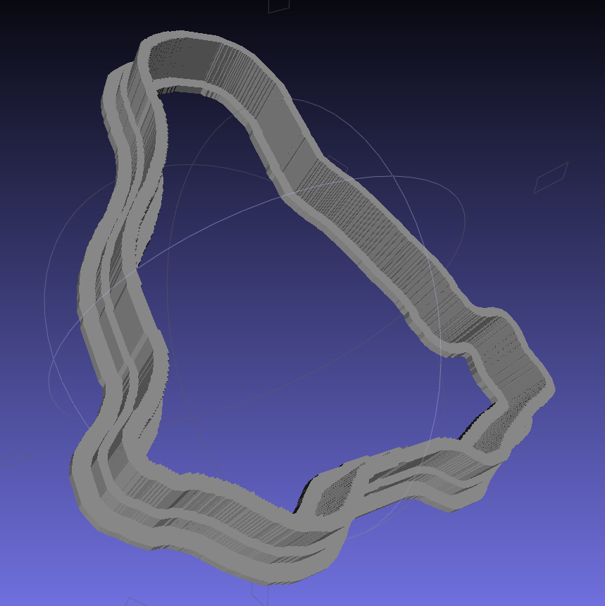
The cookie cutter (TuxTrace-cutter.stl), with a stiffening lip extending on both sides of the cutting blade:
TuxTrace-cutter – solid model
The press probably won’t slide into the cutter, because I set things up to use the same dimensions, and certainly won’t fit inside the inner lip on the build platform. Another Minkowski around the press to add half a millimeter or so would let them nest together, at the cost of even more computation time.
Those nicely shaded blue images come from MeshLab screenshots, which you can (and should!) install on your Linux box without any hassle at all.
The “blade” isn’t particularly sharp, due to the fact that we’re printing blocky pixels. I produced a very thin blade for the original Tux Cutter by using a finicky collection of settings, but that won’t produce a corresponding press.
The surface that OpenSCAD builds from the height map image has slightly tapering walls, because that’s how it ensures a 2-manifold 3D object. The base of the walls will be slightly wider than the grayscale line width and the top will be slightly narrower. This produces a tapered edge, which is probably what you want for a cookie cutter, but it means you must make the lines wide enough to ensure good fill along the top of the wall.
The G-Code produced from the height map image above looks like this at the base of the walls on the press (as always, clicky for more dots):
TuxTrace-press – G-Code Layer 27
The same walls become much thinner on the top layer, including a few single-thread sections:
TuxTrace-press – G-Code Layer 35
Moral of the story: draw with a chunky marker!
Bonus lesson: always analyze the G-Code before you build anything…
The Bash script produces several intermediate images and data files along the way; delete them if you like.
A cropped / rotated / de-commented / contrast-stretched image (TuxTrace_prep.png):
TuxTrace_prep
An image (TuxTrace_plate.pgm and .dat) that defines the outside edge, with no interior detail, to shape the cutter outline:
TuxTrace_plate
An image (TuxTrace_map.pgm and .dat) that defines the height map for the press surface:
TuxTrace_map
That one is actually identical to the incoming PNG file, just converted to an ASCII image file format.