The Smell of Molten Projects in the Morning

Ed Nisley's Blog: Shop notes, electronics, firmware, machinery, 3D printing, laser cuttery, and curiosities. Contents: 100% human thinking, 0% AI slop.

Tag: CNC-3018XL

Small gantry router

  • CNC 3018-Pro: Home Switches

    The CNC 3018-Pro doesn’t absolutely need home switches, but (in principle) they let you install a workholding fixture at a known position, home the axes, pick a preset coordinate system for the fixture, and not have to touch off the axes before making parts.

    Having used Makerbot-style endstop switch PCBs for the MPCNC, this was straightforward:

    3018 CNC - Endstop switches - overview
    3018 CNC – Endstop switches – overview

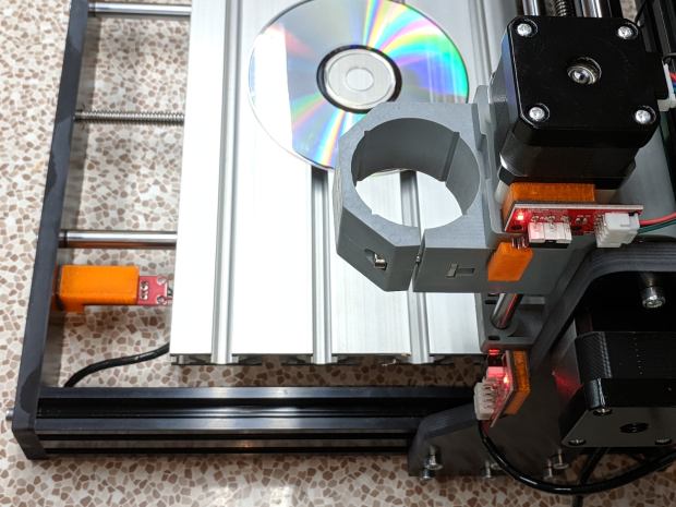
    The X and Z axis switches simply press against the appropriate moving parts:

    3018 CNC - X and Z Endstops
    3018 CNC – X and Z Endstops

    The little tab stuck on the tool clamp provides a bit of clearance around the upper part of the X axis assembly.

    The Y axis switch needed a slightly tapered tab to extend the bearing holder:

    3018 CNC - Y axis endstop
    3018 CNC – Y axis endstop

    It’s made from a random scrap of clear plastic, hand-filed to suit, and stuck on the bearing to trigger the switch in exactly the right spot.

    You can find elaborate switch mounts on Thingiverse, but I’ve become a big fan of genuine 3M outdoor-rated foam tape for this sort of thing: aggressive stickiness, no deterioration, possible-but-not-easy removal.

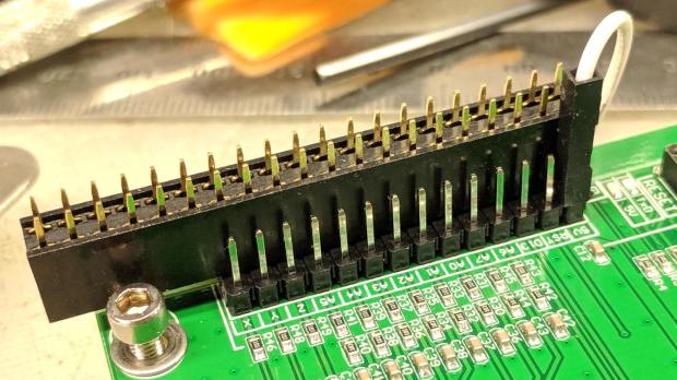
    The switches need +5 V power, so add a small hack to the CAMTool V3.3 control board to let the connectors plug right in:

    3018 CNC CAMTool - Endstop power mod - installed
    3018 CNC CAMTool – Endstop power mod – installed

    The solid models borrow their central depression around the switch terminals from the MPCNC blocks:

    3018 Home Switch Mounts - Slic3r preview
    3018 Home Switch Mounts – Slic3r preview

    The OpenSCAD source code as a GitHub Gist:

    // 3018-Pro Mount for Makerbot Endstop PCB
    // Ed Nisley KE4ZNU – 2019-07
    /* [Build Options] */
    Layout = "Show"; // [Build, Show]
    /* [Hidden] */
    ThreadThick = 0.25; // [0.20, 0.25]
    ThreadWidth = 0.40; // [0.40]
    function IntegerMultiple(Size,Unit) = Unit * ceil(Size / Unit);
    Protrusion = 0.01; // [0.01, 0.1]
    HoleWindage = 0.2;
    ID = 0;
    OD = 1;
    LENGTH = 2;
    //- Shapes
    // Basic PCB with hole for switch pins
    // origin at switch actuator corner, as seen looking at component side
    SwitchClear = [15.0,5.0,2.0]; // clearance around switch pins
    SwitchOffset = [12.5,9.0,0.0]; // center of switch pins from actuator corner
    PCB = [26.0,16.4,2*SwitchClear.z]; // switch PCB beyond connector, pin height
    XBlock = [PCB.x,PCB.y,5.0];
    module XMount() {
    difference() {
    cube(XBlock,center=false);
    translate(SwitchOffset + [0,0,XBlock.z – SwitchClear.z/2])
    cube(SwitchClear + [0,0,Protrusion],center=true);
    }
    }
    YBlock = [PCB.x + 10.0,PCB.y,20.0];
    module YMount() {
    difference() {
    translate([-10.0,0,0])
    cube(YBlock,center=false);
    translate([0,-Protrusion,10.0])
    cube(YBlock + [0,2*Protrusion,0],center=false);
    translate(SwitchOffset + [0,0,10.0 – SwitchClear.z/2])
    cube(SwitchClear + [0,0,Protrusion],center=true);
    }
    }
    ZBlock = [PCB.x,PCB.y,6.0];
    ZPin = [20.0,10.0,5.5];
    module ZMount() {
    difference() {
    cube(ZBlock,center=false);
    translate(SwitchOffset + [0,0,ZBlock.z – SwitchClear.z/2])
    cube(SwitchClear + [0,0,Protrusion],center=true);
    }
    translate([0,-ZBlock.y,0])
    difference() {
    cube(ZPin,center=false);
    translate([ZPin.x/2,-Protrusion,4.0])
    cube(ZPin + [0,2*Protrusion,0],center=false);
    }
    }
    //- Build things
    if (Layout == "Show") {
    translate([0,YBlock.y,0])
    XMount();
    translate([0,-YBlock.y/2])
    YMount();
    translate([0,-(ZBlock.y + YBlock.y)])
    ZMount();
    }

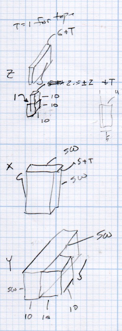
    The dimension doodles:

    3018 Home Switch Mounts - Dimension Doodles
    3018 Home Switch Mounts – Dimension Doodles
  • CNC 3018-Pro: CAMTool Modification for MBI-style Home Switches

    The Protonteer board I used on the MPCNC required a few additional pins for power to Makerbot-style home switches, so it’s no surprise the CAMTool V3.3 board on the CNC 3018-Pro gantry mill requires a similar hack:

    3018 CNC CAMTool - Endstop power mod
    3018 CNC CAMTool – Endstop power mod

    The white jumper plugs into the single +5 V pin in the row and is soldered to a straight wire running along the entire row of header pins. I pushed the black plastic strip to the bottom, soldered the wire along the pins atop it, then clipped off the pins so they’re about the right height when flush against the PCB.

    Use a two-row socket to hold the new row in alignment with the existing header:

    3018 CNC CAMTool - Endstop power mod - alignment
    3018 CNC CAMTool – Endstop power mod – alignment

    Slobber on some epoxy and let it cure:

    3018 CNC CAMTool - Endstop power mod - epoxy curing
    3018 CNC CAMTool – Endstop power mod – epoxy curing

    And then It Just Works™:

    3018 CNC CAMTool - Endstop power mod - installed
    3018 CNC CAMTool – Endstop power mod – installed

    Well, after you install the switches and tell GRBL to use them …

    Reminder: If you intend to put limit switches on both ends of the axis travel, you must clip the NC lead from both MBI switches. One switch per axis will work the way you expect and that’s how I’m using them here.

  • CNC 3018-Pro: Assembly Tweaks

    If you regard your new CNC 3018-Pro Router kit as a box of parts which could, with some adjustments and additional parts, become a small CNC router, you’re on the right track.

    In my case, the aluminum extrusions arrived somewhat squashed inside their well-padded foam shipping carton, which leads me to believe the factory responsible for tapping the bolt holes in the ends must be a fairly nasty place. In any event, the hammerhead T-nuts for the gantry struts simply didn’t fit into some sections of the slots, although they worked fine elsewhere.

    So, file a smidge off the rounded sides of a few nuts:

    3018CNC - 2020 T-nuts - filed
    3018CNC – 2020 T-nuts – filed

    Which let them slide into place and rotate properly despite the bent channel:

    3018CNC - 2020 T-nuts - trial fit
    3018CNC – 2020 T-nuts – trial fit

    The assembly instructions used a word I’d never encountered before:

    3018CNC - Gantry plate position
    3018CNC – Gantry plate position

    Turns out ubiety is exactly correct, but … raise your hand if you’ve ever heard it in polite conversation. Thought so.

    I’ve not noticed any harm from rounding off the position to 46 mm; just position both struts the same distance from the rear crossbar and it’s all good.

    The struts behind the CAMTool CNC-V3.3 electronics board were also squashed, prompting a bit more filing:

    3018CNC - CAMTool v3.3 board - trial fit
    3018CNC – CAMTool v3.3 board – trial fit

    The CAMTool board is basically an Arduino-class microcontroller preloaded with GRBL 1.1f and surrounded with spindle / stepper driver circuits.

    As with the MPCNC, I’ll dribble G-Code into it from a Raspberry Pi. Alas, the struts behind the CAMTool board are on 75 mm centers, but the Pi cases on hand have feet on 72-ish mm centers. Pay no attention to the surroundings, just drill the holes in the right spots:

    3018CNC - RPi case - drilling
    3018CNC – RPi case – drilling

    Add more T-nuts and short button head screws, with rubber pads between the case and the struts:

    3018CNC - RPi case - mounted
    3018CNC – RPi case – mounted

    It’s coming together!