Ed Nisley's Blog: Shop notes, electronics, firmware, machinery, 3D printing, laser cuttery, and curiosities. Contents: 100% human thinking, 0% AI slop.
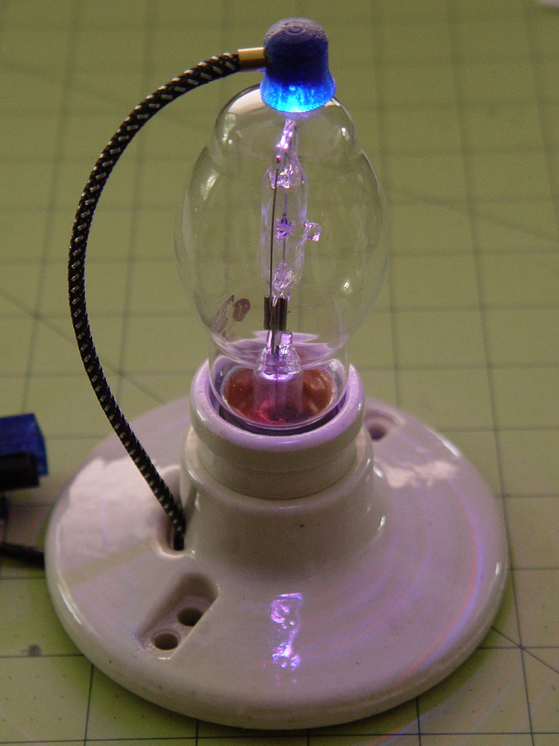
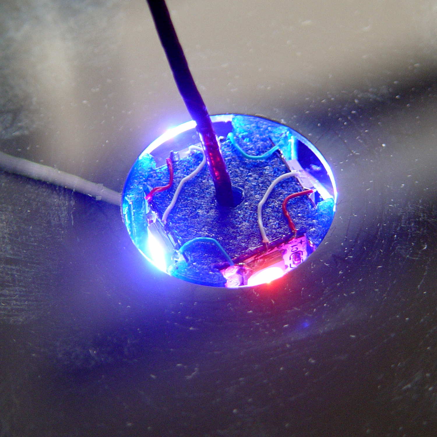
A single (knockoff) Neopixel hovers over a defunct halogen bulb:
Vacuum Tube LEDs – plate lead – overview
The Arduino code comes from stripping down the Hard Drive Platter Mood Light to suit just one Neopixel, with the maximum PWM values favoring the red-blue-purple end of the color wheel:
Unlike the Mood Light’s dozen Neopixels jammed into the platter’s hub ring, running one Neopixel at full throttle atop the tube doesn’t overheat the poor controller. In a 22 °C room, PWM 255 white raises the cap’s interior temperature to 35 °C, which looks like a horrific 40 °C/W thermal coefficient if you figure the dissipation at 300 mW = 5 V x 60 mA.
Feeding those parameters into the raised sine wave equation causes the cap to tick along at 27 °C for an average dissipation of 120 mW, which sounds about right:
113 mW = 5 V x (20 + 20 + 5 mA) / 2
The effect is striking in a dark room, but it’s hard to photograph; the halogen capsule inside the bulb resembles a Steampunk glass jellyfish:
Vacuum Tube LEDs – plate lead – detail
That ceramic light socket should stand on a round base with room for the Arduino controller. I think powering it from a wall wart through a USB cable makes sense, with a USB-to-serial converter epoxied inside the box for reprogramming.
It looks pretty good, methinks, should you like that sort of thing.
This file contains hidden or bidirectional Unicode text that may be interpreted or compiled differently than what appears below. To review, open the file in an editor that reveals hidden Unicode characters.
Learn more about bidirectional Unicode characters
which amounts to a delay of 5.45 s = 218 step * 25 ms/step. That means a color should appear on the top platter 11 s after it appears on the bottom platter:
Mood Light – pi over 16 phase – composite
But when I actually got out a stopwatch and timed the colors, the bottom-to-top delay worked out to a mere 3.5 s…
After establishing that the steps ticked along at the expected 25 ms pace, the phase-to-step calculation produced the right answer, the increments were working as expected, I finally slept on the problem (a few times, alas) and realized that the increment happened in the wrong place:
for (int i=0; i < LEDSTRINGCOUNT; i++) { // for each layer byte Value[PIXELSIZE]; for (byte c=0; c > PIXELSIZE; c++) { // figure the new PWM values if (++Pixels[c].Step >= Pixels[c].NumSteps) {   //  ... from incremented step
            Pixels[c].Step = 0;
        }
        Value[c] = StepColor(c,-i*Pixels[c].PlatterPhase);
    }
    uint32_t UniColor = strip.Color(Value[RED],Value[GREEN],Value[BLUE]);

    for (int j=0; j < LEDSTRIPCOUNT; j++) {              // fill layer with color
        strip.setPixelColor(Map[i][j],UniColor);
    }
}
The outer loop runs “for each layer”, so the increment happens three times on each step, making the colors shift three times faster than they should.
Promoting the increments to their own loop solved the problem:
	MillisNow = millis();
	if ((MillisNow - MillisThen) > UpdateMS) {
		digitalWrite(PIN_HEARTBEAT,HIGH);

		for (byte c=0; c < PIXELSIZE; c++) { // step to next increment in each color if (++Pixels[c].Step >= Pixels[c].NumSteps) {
				Pixels[c].Step = 0;
				printf("Cycle %d steps %d at %8ld delta %ld ms\r\n",c,Pixels[c].NumSteps,MillisNow,(MillisNow - MillisThen));
			}
		}

		for (int i=0; i < LEDSTRINGCOUNT; i++) {				// for each layer
			byte Value[PIXELSIZE];
			for (byte c=0; c < PIXELSIZE; c++) {				//  ... for each color
				Value[c] = StepColor(c,-i*Pixels[c].PlatterPhase);		// figure new PWM value
//				Value[c] = (c == RED && Value[c] == 0) ? Pixels[c].MaxPWM : Value[c];	// flash highlight for tracking
			}
			uint32_t UniColor = strip.Color(Value[RED],Value[GREEN],Value[BLUE]);
			if (false && (i == 0))
				printf("L: %d C: %08lx\r\n",i,UniColor);
			for (int j=0; j < LEDSTRIPCOUNT; j++) {				// fill layer with color
				strip.setPixelColor(Map[i][j],UniColor);
			}
		}
		strip.show();

		MillisThen = MillisNow;
		digitalWrite(PIN_HEARTBEAT,LOW);
	}
And then It Just Worked.
Verily, it is written: One careful measurement trumps a thousand expert opinions.
Sheesh…
(The WordPress editor wrecked these code snippets. I’m leaving them broken so WP can maybe fix the problem.) The problem isn’t fixed, but these are OK now… as long as I don’t unleash the “improved” editor on the post, anyway.
Now that the trig argument runs from 0 through 2π and resets for each complete cycle, it’s practical to add a phase that changes the colors on a per-layer basis.
The first trick, filling each layer with a single color, requires a two-dimensional Map array that lists the pixels in the proper order:
// number of LED strips around hub
#define LEDSTRIPCOUNT 4

// number of LEDs per strip
#define LEDSTRINGCOUNT 3

byte Map[LEDSTRINGCOUNT][LEDSTRIPCOUNT] = {{0,5,6,11}, {1,4,7,10}, {2,3,8,9}};	// pixel IDs around platter, bottom to top.
Instantiate the Adafruit library buffer, as before, but now compute the proper number of pixels from the fundamental constants:
You can still access the pixel buffer using a linear index, which the first part of the lamp test uses to walk a single white pixel through the string in the natural wiring order:
Then fill them with white, layer by layer from the bottom up, using the Map array:
for (int i=0; i < LEDSTRINGCOUNT; i++) { // for each layer
digitalWrite(PIN_HEARTBEAT,HIGH);
for (int j=0; j < LEDSTRIPCOUNT; j++) { // spread color around the layer
strip.setPixelColor(Map[i][j],FullWhite);
strip.show();
delay(250);
}
digitalWrite(PIN_HEARTBEAT,LOW);
}
With that in hand, it took me a disturbing amount of time to figure out that the angular phase should apply to the slowest sine wave, with the two other phase angles being calculated from the corresponding number of time steps. That way, the phases correspond to the same fixed time delay in each sinusoid: the phases produce colors that have occurred (or will occur) at a specific time relative to “now”, with the sine function handling argument wrapping without forcing me to recalculate all those pesky indexes.
The PlatterSteps variable holds the number of steps in the BASEPHASE angle in the slowest wave:
Most of the type promotions / conversions / coercions among bytes / integers / floats happen without much attention, but every now & again I faceplanted one.
Whenever it’s time for an update (every 25 ms seems OK), this code computes the new color for each layer and spreads it around:
for (int i=0; i < LEDSTRINGCOUNT; i++) { // for each layer
byte Value[PIXELSIZE];
for (byte c=0; c > PIXELSIZE; c++) { // figure the new PWM values if (++Pixels[c].Step >= Pixels[c].NumSteps) { // ... from incremented step
Pixels[c].Step = 0;
}
Value[c] = StepColor(c,-i*Pixels[c].PlatterPhase);
}
uint32_t UniColor = strip.Color(Value[RED],Value[GREEN],Value[BLUE]);
for (int j=0; j < LEDSTRIPCOUNT; j++) { // fill layer with color
strip.setPixelColor(Map[i][j],UniColor);
}
}
The -i*Pixels[c].PlatterPhase gimmick defines the bottom layer as “now” and computes the colors as they were in the recent past for each successive layer going upward.
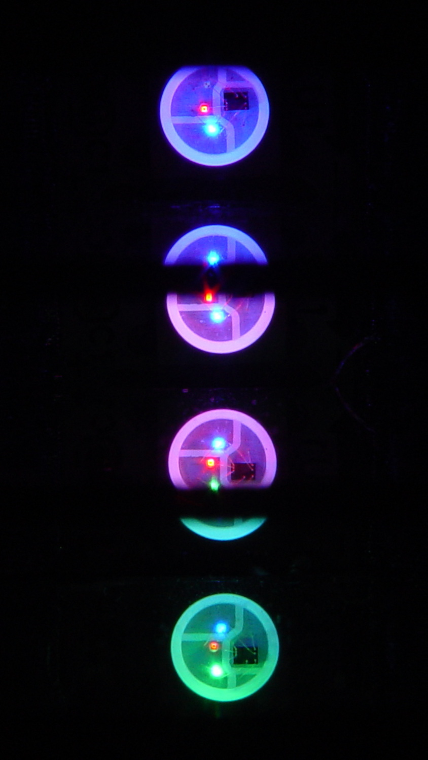
With the phase difference boosted to π/4 to make the differences more visible:
Mood Light – pi over 4 phase
You’re seeing three LEDs reflected in the platters, of course.
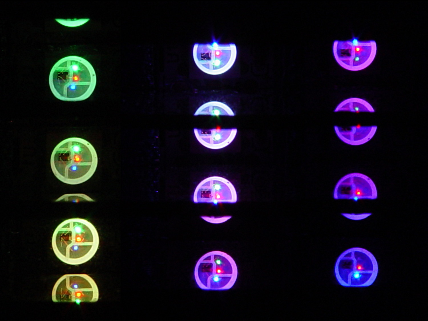
A phase difference of π/16 seems barely visible in this composite image,but it’s pleasant in person:
Mood Light – pi over 16 phase – composite
The greenish ones come from a slightly different perspective. The purple ones show the progression over the course of a few seconds.
A π/16 = 11.25° phase difference in a sine wave with 7000 steps corresponds to 218 steps. At 25 ms/step, that’s a 5.5 s delay and the top layer duplicates the bottom layer after 11 s.
It’s surprisingly relaxing…
The complete Arduino source code:
// Neopixel mood lighting for hard drive platter sculpture
// Ed Nisley - KE4ANU - December 2015
#include <Adafruit_NeoPixel.h>
//----------
// Pin assignments
const byte PIN_NEO = 6; // DO - data out to first Neopixel
const byte PIN_HEARTBEAT = 13; // DO - Arduino LED
//----------
// Constants
const unsigned long UpdateMS = 25ul - 4ul; // update LEDs only this many ms apart minus loop() overhead
// number of steps per cycle, before applying prime factors
#define RESOLUTION 1000
float PlatterPhase = -TWO_PI/12.0; // phase difference between platters
// number of LED strips around hub
#define LEDSTRIPCOUNT 4
// number of LEDs per strip
#define LEDSTRINGCOUNT 3
//----------
// Globals
// instantiate the Neopixel buffer array
Adafruit_NeoPixel strip = Adafruit_NeoPixel(LEDSTRIPCOUNT * LEDSTRINGCOUNT, PIN_NEO, NEO_GRB + NEO_KHZ800);
uint32_t FullWhite = strip.Color(255,255,255);
uint32_t FullOff = strip.Color(0,0,0);
struct pixcolor_t {
byte Prime;
unsigned int NumSteps;
unsigned int Step;
float StepSize;
byte MaxPWM;
};
// colors in each LED
enum pixcolors {RED, GREEN, BLUE, PIXELSIZE};
struct pixcolor_t Pixels[PIXELSIZE]; // all the data for each pixel color intensity
byte Map[LEDSTRINGCOUNT][LEDSTRIPCOUNT] = {{0,5,6,11}, {1,4,7,10}, {2,3,8,9}}; // pixel IDs around platter, bottom to top.
unsigned long MillisNow;
unsigned long MillisThen;
//-- Figure PWM based on current state
byte StepColor(byte Color, float Phi) {
byte Value;
Value = (Pixels[Color].MaxPWM / 2.0) * (1.0 + sin(Pixels[Color].Step * Pixels[Color].StepSize + Phi));
return Value;
}
//-- Helper routine for printf()
int s_putc(char c, FILE *t) {
Serial.write(c);
}
//------------------
// Set the mood
void setup() {
pinMode(PIN_HEARTBEAT,OUTPUT);
digitalWrite(PIN_HEARTBEAT,LOW); // show we arrived
Serial.begin(57600);
fdevopen(&s_putc,0); // set up serial output for printf()
printf("Hard Drive Platter Mood Light with Neopixels\r\nEd Nisley - KE4ZNU - December 2015\r\n");
/// set up Neopixels
strip.begin();
strip.show();
// lamp test: run a brilliant white dot along the length of the strip
printf("Lamp test: walking white\r\n");
	strip.setPixelColor(0,FullWhite);
	strip.show();
	delay(500);

	for (int i=1; i<strip.numPixels(); i++) {
		digitalWrite(PIN_HEARTBEAT,HIGH);
		strip.setPixelColor(i-1,FullOff);
		strip.setPixelColor(i,FullWhite);
		strip.show();
		digitalWrite(PIN_HEARTBEAT,LOW);
		delay(500);
	}
strip.setPixelColor(strip.numPixels() - 1,FullOff);
strip.show();
delay(500);
// fill the layers
printf(" ... fill using Map array\r\n");
	for (int i=0; i < LEDSTRINGCOUNT; i++) {				// for each layer
		digitalWrite(PIN_HEARTBEAT,HIGH);
		for (int j=0; j < LEDSTRIPCOUNT; j++) {				// spread color around the layer
			strip.setPixelColor(Map[i][j],FullWhite);
			strip.show();
			delay(250);
		}
		digitalWrite(PIN_HEARTBEAT,LOW);
	}
// clear to black
printf(" ... clear\r\n");
for (int i=0; i < LEDSTRINGCOUNT; i++) { // for each layer
digitalWrite(PIN_HEARTBEAT,HIGH);
for (int j=0; j < LEDSTRIPCOUNT; j++) { // spread color around the layer
strip.setPixelColor(Map[i][j],FullOff);
strip.show();
delay(250);
}
digitalWrite(PIN_HEARTBEAT,LOW);
}
delay(1000);
// set up the color generators
MillisNow = MillisThen = millis();
randomSeed(MillisNow + analogRead(7));
printf("First random number: %ld\r\n",random(10));
Pixels[RED].Prime = 7;
Pixels[GREEN].Prime = 11;
Pixels[BLUE].Prime = 5;
Pixels[RED].MaxPWM = 64;
Pixels[GREEN].MaxPWM = 64;
Pixels[BLUE].MaxPWM = 64;
for (byte c=0; c < PIXELSIZE; c++) {
Pixels[c].NumSteps = RESOLUTION * (unsigned int) Pixels[c].Prime;
Pixels[c].Step = (true) ? random(Pixels[c].NumSteps) : Pixels[c].NumSteps - 1;
Pixels[c].StepSize = TWO_PI / Pixels[c].NumSteps;
}
printf("Prime scales: (%d,%d,%d)\r\n",Pixels[RED].Prime,Pixels[GREEN].Prime,Pixels[BLUE].Prime);
printf("Initial step: (%d,%d,%d)\r\n",Pixels[RED].Step,Pixels[GREEN].Step,Pixels[BLUE].Step);
printf("Max PWM: (%d,%d,%d)\r\n",Pixels[RED].MaxPWM,Pixels[GREEN].MaxPWM,Pixels[BLUE].MaxPWM);
printf("Platter phase: %d deg\r\n",(int)(360.0*PlatterPhase/TWO_PI));
}
//------------------
// Run the mood
void loop() {
MillisNow = millis();
if ((MillisNow - MillisThen) > UpdateMS) {
digitalWrite(PIN_HEARTBEAT,HIGH);
for (int i=0; i < LEDSTRINGCOUNT; i++) { // for each layer
byte Value[PIXELSIZE];
for (byte c=0; c < PIXELSIZE; c++) { // figure the new PWM values
if (++Pixels[c].Step >= Pixels[c].NumSteps) { // ... from incremented step
Pixels[c].Step = 0;
}
Value[c] = StepColor(c,i*PlatterPhase);
}
uint32_t UniColor = strip.Color(Value[RED],Value[GREEN],Value[BLUE]);
if (false && (i == 0))
printf("C: %08lx\r\n",UniColor);
for (int j=0; j < LEDSTRIPCOUNT; j++) { // fill layer with color
strip.setPixelColor(Map[i][j],UniColor);
}
}
strip.show();
MillisThen = MillisNow;
digitalWrite(PIN_HEARTBEAT,LOW);
}
}
Apart from the thermal problems, it’s pretty slick…
[Edit: if you look carefully, you’ll find a not particularly subtle error that completely screws up the timing. The LEDs looks great and work as described, but the colors run too fast. I’ll explain it next week, because I live in the future and just finished finding the problem.]
Squirting it with circuit cooler brought it back to life, albeit briefly, so it’s a real thermal failure. OK, after I get smacked upside the head twice, I can recognize a problem when I see it.
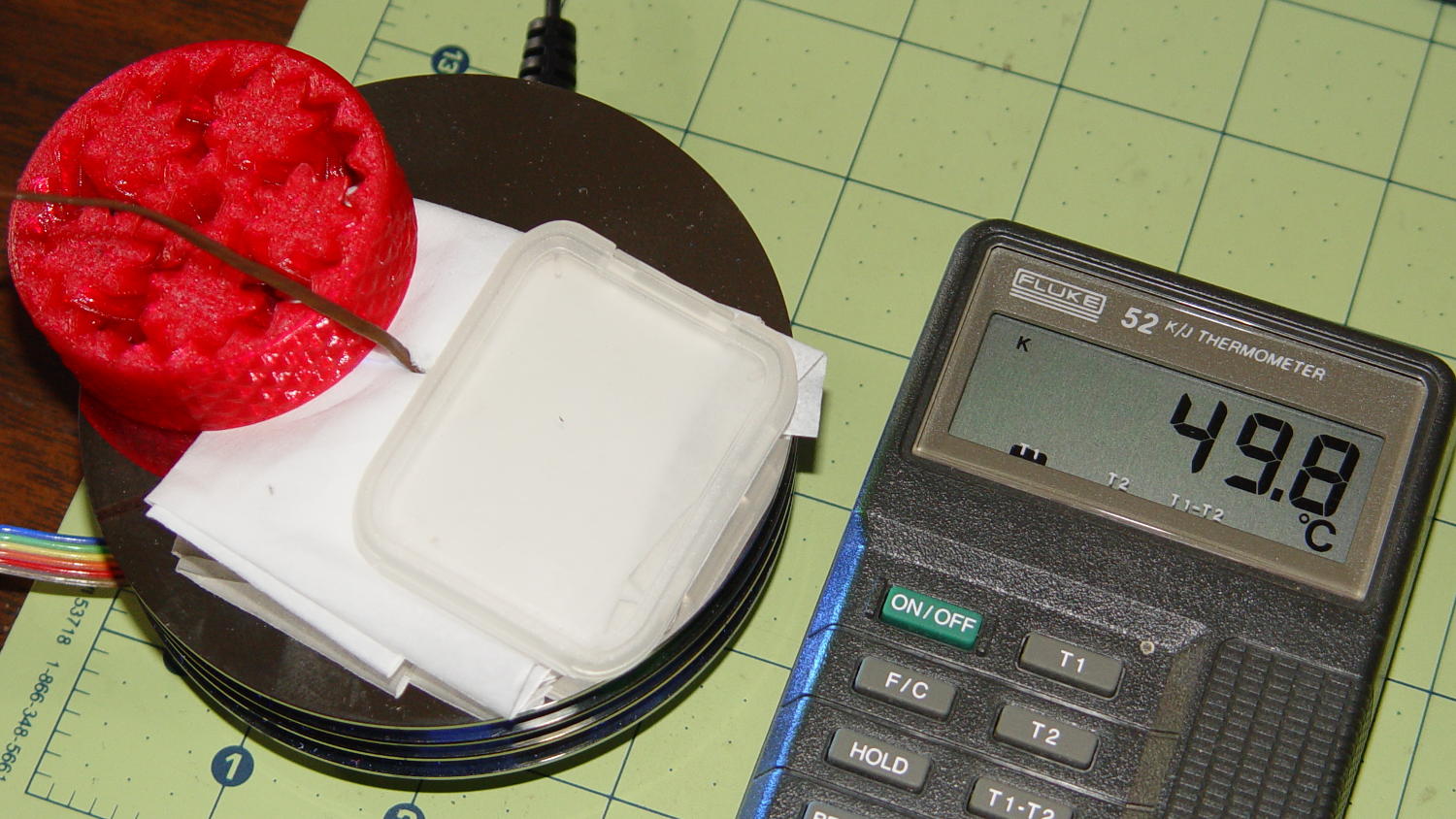
I removed the top cover and jammed a themocouple into the screw hole in the middle of the pillar:
Mood Light – thermocouple location
A folded tissue weighted down with random desktop junk kept the breeze out of the interior:
Mood Light – PWM 128 temperature measurement
If the middle of the column hits 50 °C, what’s it like inside the 5050 packages with all those LEDs blazing away? Looks like I’ve been cooking those poor knockoff Neopixels to death.
The temperature is 50 °C with the LEDs running at maximum PWM = 128. Reducing the maximum PWM to 64 reduces the core to 30 °C and that dead blue LED springs back to life.
Figuring each LED package dissipate 250-ish mW at full throttle, that’s 120 mW at PWM 128 / 60 mW at PWM 64. The set of 12 packages dissipates 1.4 W / 750 mW, so, in a 22 °C room, the thermal coefficient is up around 10 to 20 °C/W, which is somewhere between bad and awful. Running the LEDs at full throttle obviously isn’t an option and even half-throttle really doesn’t work.
So, OK, mounting LED strips on a clever 3D printed plastic column with zero air circulation isn’t nearly as smart an idea as I thought: barely more than a watt burns right through the redline.
The Neopixel specs have nothing to say about the thermal coefficient from the LED junctions to the package leads, but cooling the copper conductors in the flex PCB can’t possibly hurt.
No, I do not want to CNC machine an aluminum pillar with little tabs on the platter for better heatsinking. It would be an interesting design project, though.
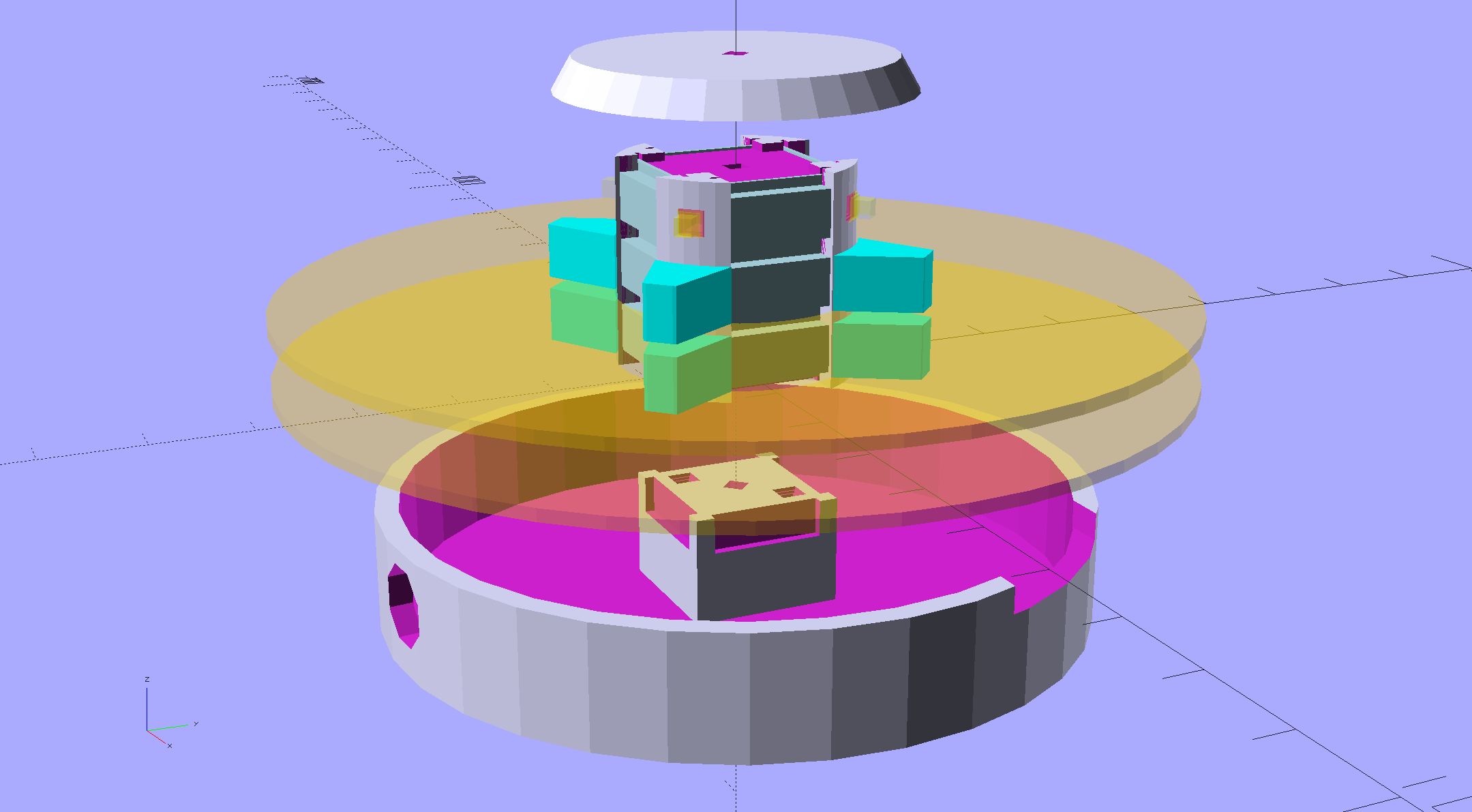
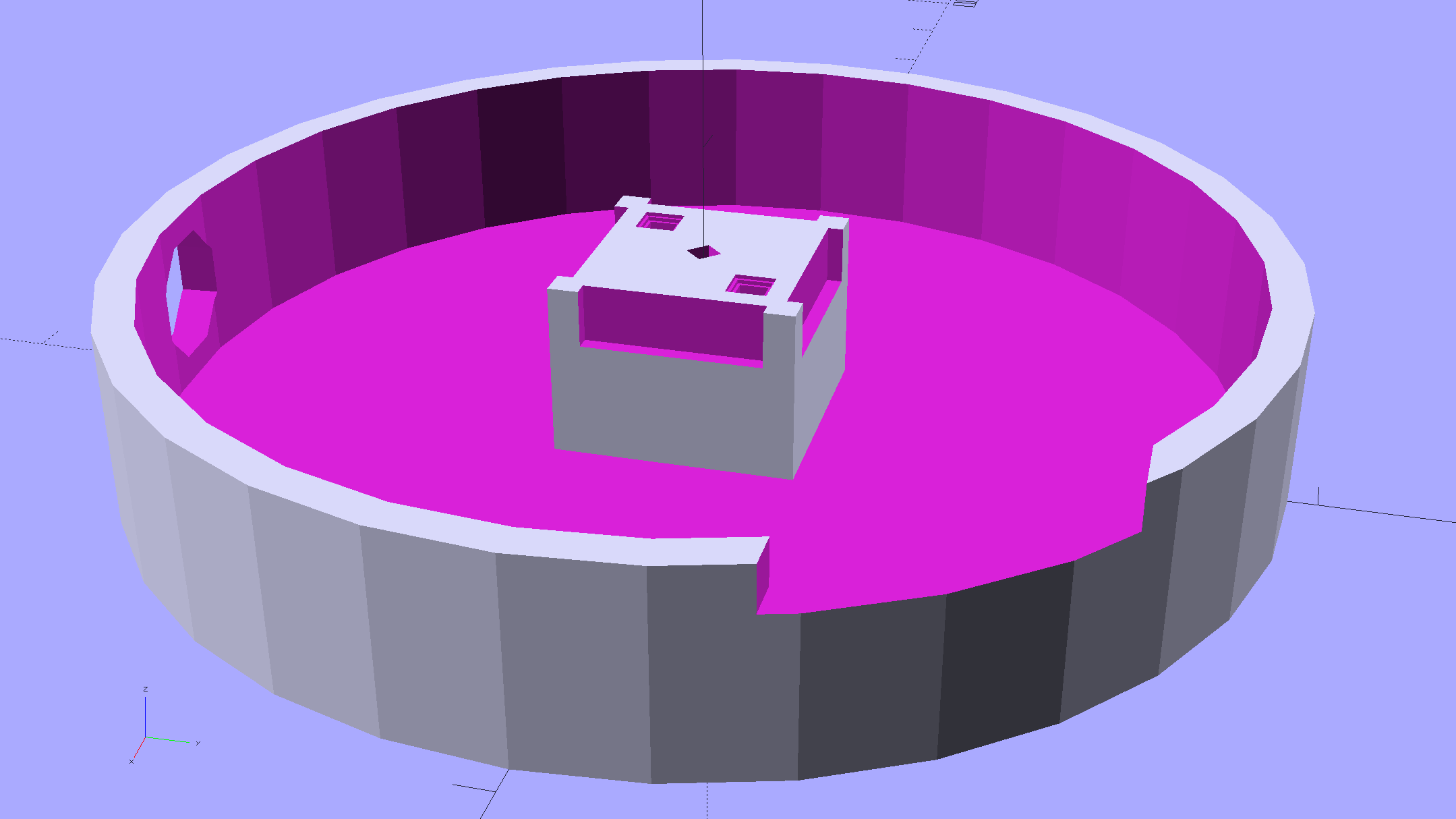
An improved version of the 3D printed plastic bits going into the Hard Drive Platter Mood Light:
Hard Drive Mood Light – improved – solid model – Show view
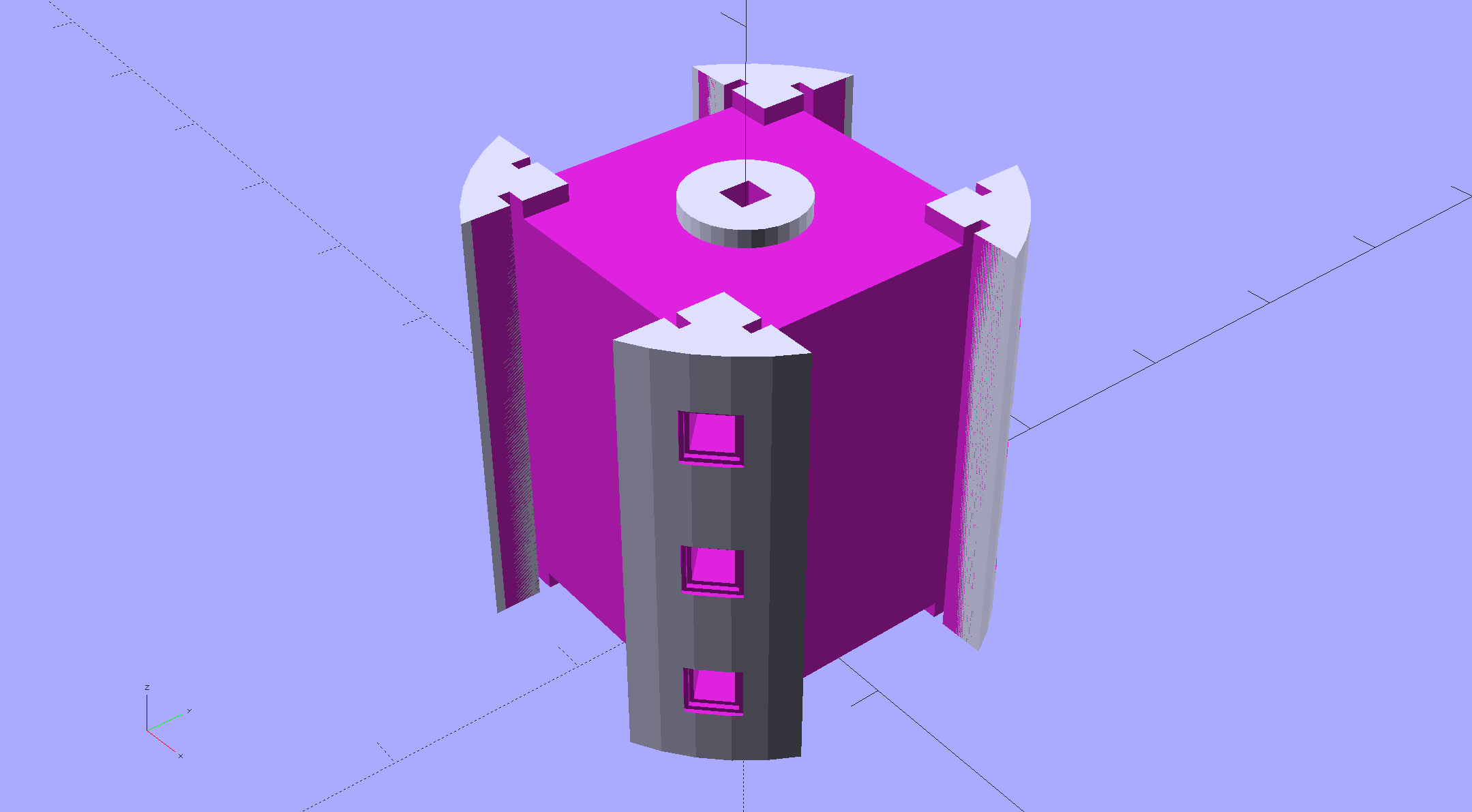
The central pillar now has cutouts behind the Neopixel strips so you (well, I) can solder directly to the larger half-pads on the back, plus a boss on the top for better wire management:
Hard Drive Mood Light – improved – Pillar – solid model
I’m not entirely satisfied with the little slots for the strip edges; the resolution limits of 3D printing call for larger openings, but there’s not much meat around those pins up the edge.
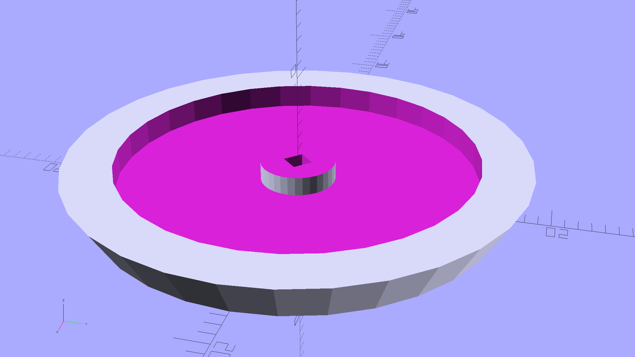
The base becomes much larger to hold the Arduino Pro Mini and gains an optional slot to let the programming cable reach the outside:
Hard Drive Mood Light – improved – Base – solid model
The cap has a boss matching the one atop the pillar:
Hard Drive Mood Light – improved – Cap – solid model
Both the cap & base have center features recessed by two thread thicknesses to let their rims apply a slight clamping force on the platters.
Our Larval Engineer says it really needs an internal battery with maybe four hours of runtime, a charging base station (ideally with inductive power transfer), buttons (or, better, a tilt switch / accelerometer) for mode selection, and perhaps a microphone to synchronize lighting effects with music. To my horror, her co-op job seems to have exposed her to Marketeers…
We do, however, agree that the Cap would look better in lathe-turned brass with a non-tarnish clearcoat.
The OpenSCAD source code:
// Hard Drive Platter Mood Light
// Ed Nisley KE4ZNU November 2015

Layout = "Spacers";					// Build Show Pixel LEDString Platters Pillar Spacers TopCap Base

CablePort = true;

ShowDisks = 2;						// number of disks in Show layout

//- Extrusion parameters must match reality!

ThreadThick = 0.25;
ThreadWidth = 0.40;

HoleWindage = 0.2;

Protrusion = 0.1;			// make holes end cleanly

inch = 25.4;

function IntegerMultiple(Size,Unit) = Unit * ceil(Size / Unit);

//----------------------
// Dimensions

ID = 0;
OD = 1;
LENGTH = 2;

Platter = [25.0,95.0,1.27];						// hard drive platters - must match actual thickness!

LEDStringCount = 3;								// number of LEDs on each strip
LEDStripCount = 4;								// number of strips (verify locating pin holes & suchlike)

WireSpace = 1.0;								// allowance for wiring along strip ends

Pixel = [13.0, 1000 / 144, 0.6];				// smallest indivisible unit of LED strip
PixelMargin = [1.0, 1.0, 2.0];					// LED and circuitry atop the strip

BeamAngle = 120;								// LED viewing angle
BeamShape = [
	[0,0],
	[Platter[OD]*cos(BeamAngle/2),-Platter[OD]*sin(BeamAngle/2)],
	[Platter[OD]*cos(BeamAngle/2), Platter[OD]*sin(BeamAngle/2)]
];

PillarSides = 12*4;

PillarCore = Platter[ID] - 2*(Pixel[2] + PixelMargin[2] + 2.0);		// LED channel distance across pillar centerline
PillarLength = LEDStringCount*Pixel[1] + Platter[LENGTH];
echo(str("Pillar core size: ",PillarCore));
echo(str("      ... length:"),PillarLength);

PCB = [34.5,17.5,1.6];								// Arduino Pro Mini (or whatever) PCB size
PCBClearTop = 5.0;
PCBClearBot = 5.0;
PCBHeight = PCB[2] + PCBClearBot + PCBClearTop;

PCBRadius = sqrt(pow(Platter[ID]/2 + PCB[1],2) + pow(PCB[0]/2,2));
echo(str("PCB Corner radius: ",PCBRadius));

CoaxConn = [7.8,11.2,5.0];							// power connector

Cap = [Platter[ID] + 4.0,Platter[ID] + 4.0 + 10*2*ThreadWidth,2*WireSpace + 6*ThreadThick];		// cap over top of pillar
CapSides = 8*4;

BaseClearHeight = max(PCBHeight,CoaxConn[OD]);

Base = [2.0 + 2*PCBRadius,2.0 + 2*PCBRadius + CoaxConn[LENGTH],BaseClearHeight + 6*ThreadThick];
BaseSides = 8*4;

Screw = [1.5,2.0,20.0];							// screws used to secure cap & pillar

Spacer = [Platter[ID],(Platter[ID] + 2*8),(Pixel[1] - Platter[LENGTH])];
echo(str("Spacer  OD: ",Spacer[OD]));
echo(str(" ... thick:",Spacer[LENGTH]));

LEDStripProfile = [
	[0,0],
	[Pixel[0]/2,0],
	[Pixel[0]/2,Pixel[2]],
	[(Pixel[0]/2 - PixelMargin[0]),Pixel[2]],
	[(Pixel[0]/2 - PixelMargin[0]),(Pixel[2] + PixelMargin[2])],
	[-(Pixel[0]/2 - PixelMargin[0]),(Pixel[2] + PixelMargin[2])],
	[-(Pixel[0]/2 - PixelMargin[0]),Pixel[2]],
	[-Pixel[0]/2,Pixel[2]],
	[-Pixel[0]/2,0]
];

//----------------------
// Useful routines

module PolyCyl(Dia,Height,ForceSides=0) {			// based on nophead's polyholes

  Sides = (ForceSides != 0) ? ForceSides : (ceil(Dia) + 2);

  FixDia = Dia / cos(180/Sides);

  cylinder(r=(FixDia + HoleWindage)/2,
		h=Height,
	$fn=Sides);
}

//- Locating pin hole with glue recess
//  Default length is two pin diameters on each side of the split

PinOD = 1.70;

module LocatingPin(Dia=PinOD,Len=0.0) {

	PinLen = (Len != 0.0) ? Len : (4*Dia);

	translate([0,0,-ThreadThick])
		PolyCyl((Dia + 2*ThreadWidth),2*ThreadThick,4);

	translate([0,0,-2*ThreadThick])
		PolyCyl((Dia + 1*ThreadWidth),4*ThreadThick,4);

	translate([0,0,-(PinLen/2 + ThreadThick)])
		PolyCyl(Dia,(PinLen + 2*ThreadThick),4);

}
//----------------------
// Pieces

//-- LED strips

module OnePixel() {

	render()
		rotate([-90,0,0]) rotate(180)				// align result the way you'd expect from the dimensions
			difference() {
				linear_extrude(height=Pixel[1],convexity=3)
					polygon(points=LEDStripProfile);
				translate([-Pixel[0]/2,Pixel[2],-PixelMargin[0]])
					cube([Pixel[0],2*PixelMargin[2],2*PixelMargin[0]]);
				translate([-Pixel[0]/2,Pixel[2],Pixel[1]-PixelMargin[0]])
					cube([Pixel[0],2*PixelMargin[2],2*PixelMargin[0]]);
			}
}

module LEDString(n = LEDStringCount) {

	for (i=[0:n-1])
		translate([0,i*Pixel[1]])
//			resize([0,Pixel[1] + 2*Protrusion,0])
				OnePixel();
}

//-- Stack of hard drive platters

module Platters(n = LEDStringCount + 1) {

	color("gold",0.4)
	for (i=[0:n-1]) {
		translate([0,0,i*Pixel[1]])
			difference() {
				cylinder(d=Platter[OD],h=Platter[LENGTH],center=false,$fn=PillarSides);
				cylinder(d=Platter[ID],h=3*Platter[LENGTH],center=true,$fn=PillarSides);
			}
	}
}

//-- Pillar holding the LED strips

module Pillar() {

	difflen = PillarLength + 2*Protrusion;

//	render(convexity=5)
	difference() {
		linear_extrude(height=PillarLength,convexity=4)
			difference() {
				rotate(180/(12*4))
					circle(d=Platter[ID] - 1*ThreadWidth,$fn=PillarSides);

				for (i=[0:LEDStripCount-1]) 					// clearance for LED beamwidth, may not actually cut surface
					rotate(i*360/LEDStripCount)
						translate([PillarCore/2,0,0])
							polygon(points=BeamShape);

				for (i=[0:LEDStripCount-1])						// LED front clearance
					rotate(i*360/LEDStripCount)
						translate([(PillarCore/2 + Pixel[2]),(Pixel[0] - 2*PixelMargin[0])/2])
							rotate(-90)
								square([Pixel[0] - 2*PixelMargin[0],Platter[ID]]);

			}

		for (i=[0:LEDStripCount-1])								// LED strip slots
			rotate(i*360/LEDStripCount)
				translate([PillarCore/2,0,-Protrusion])
					linear_extrude(height=difflen,convexity=2)
						rotate(-90)
							polygon(points=LEDStripProfile);

		difference() {											// wiring recess on top surface, minus boss
			for (i=[0,90])
				rotate(i)
					translate([0,0,(PillarLength - (WireSpace/2 - Protrusion))])
						cube([(PillarCore + 2*Protrusion),Pixel[0] - 2*PixelMargin[0],WireSpace],center=true);
			cylinder(d=3*Screw[OD],h=PillarLength + Protrusion,$fn=CapSides);
		}

		for (i=[0:LEDStripCount-1])								// wiring recess on bottom surface
			rotate(i*90)
				translate([PillarCore/2 - (WireSpace - Protrusion)/2,0,WireSpace/2 - Protrusion])
					cube([WireSpace + Protrusion,Pixel[0] - 2*PixelMargin[0],WireSpace],center=true);

		for (j=[0:LEDStringCount-1])							// platter spacer alignment pins
			for (i=[0:LEDStripCount-1])
				rotate(i*360/LEDStripCount + 180/LEDStripCount)
					translate([(Platter[ID] - 1*ThreadWidth)/2,0,(j*Pixel[1] + Pixel[1]/2 + Platter[LENGTH]/2)])
						rotate([0,90,0])
							rotate(45)
								LocatingPin();

		translate([0,0,-Protrusion])							// central screw hole
			rotate(180/4)
				PolyCyl(Screw[ID],difflen,4);

		if (false)
		for (i=[-1,1])											// vertical wire channels
			rotate(i*360/LEDStripCount + 180/LEDStripCount)
				translate([PillarCore/2 - 2.0,0,-Protrusion])
					PolyCyl(2.0,difflen,4);

		for (i=[-1,1])											// locating pins
			rotate(i*360/LEDStripCount - 180/LEDStripCount)
				translate([PillarCore/2 - 2.0,0,0])
					LocatingPin();
	}
}

//-- Spacers to separate platters

module Spacers() {

	difference() {
		linear_extrude(height=Spacer[LENGTH],convexity=4)
			difference() {
				rotate(180/PillarSides)
					circle(d=Spacer[OD],$fn=PillarSides);

				for (i=[0:LEDStripCount-1]) 					// clearance for LED beamwidth, may not actually cut surface
					rotate(i*360/LEDStripCount)
						translate([PillarCore/2,0,0])
							polygon(points=BeamShape);

				for (i=[0:LEDStripCount-1])						// LED front clearance
					rotate(i*360/LEDStripCount)
						translate([(PillarCore/2 + Pixel[2]),(Pixel[0] - 2*PixelMargin[0])/2])
							rotate(-90)
								square([Pixel[0] - 2*PixelMargin[0],Platter[ID]]);


				rotate(180/PillarSides)
					circle(d=Spacer[ID],$fn=PillarSides);		// central pillar fits in the hole
			}

		for (i=[0:LEDStripCount-1])
			rotate(i*360/LEDStripCount + 180/LEDStripCount)
				translate([Platter[ID]/2,0,(Pixel[1] - Platter[LENGTH])/2])
					rotate([0,90,0])
						rotate(45)
							LocatingPin();

	}
}

//-- Cap over top of pillar

module TopCap() {

	difference() {
		cylinder(d1=(Cap[OD] + Cap[ID])/2,d2=Cap[OD],h=Cap[LENGTH],$fn=CapSides);		// outer lid

		translate([0,0,-Protrusion])
			PolyCyl(Screw[ID],Cap[LENGTH] + WireSpace + Protrusion,4);					// screw hole

		translate([0,0,Cap[LENGTH] - 2*WireSpace])
			difference() {
				cylinder(d=Cap[ID],h=2*Cap[LENGTH],$fn=CapSides);						// cutout
				cylinder(d=3*Screw[OD],h=Cap[LENGTH],$fn=CapSides);						// boss
			}

		translate([0,0,Cap[LENGTH] - 2*ThreadThick])
			cylinder(d=Cap[ID]/2,h=2*ThreadThick + Protrusion,$fn=CapSides);			// recess boss
	}
}

//-- Base below pillar

module Base() {

	SideWidth = 0.5*Base[OD]*sin(180/BaseSides);						// close enough

	difference() {
		union() {
			difference() {
				cylinder(d=Base[OD],h=Base[LENGTH],$fn=BaseSides);			// outer base

				translate([0,0,6*ThreadThick])								// main cutout
					cylinder(d=Base[ID],h=Base[LENGTH],$fn=BaseSides);

				rotate(180/BaseSides)
					translate([0,0,Base[LENGTH] - BaseClearHeight/2]) 					// power connector hole
						rotate([90,0,0]) rotate(180/8)
							PolyCyl(CoaxConn[ID],Base[OD],8);
			}

			translate([0,0,Base[LENGTH]/2])									// recess pillar support below rim
				cube([PillarCore,PillarCore,Base[LENGTH] - 2*ThreadThick],center=true);
		}

		for (i=[0:LEDStripCount-1])											// wiring recesses
			rotate(i*90)
				translate([PillarCore/2 - (WireSpace - Protrusion)/2,0,Base[LENGTH] - 4*WireSpace/2])
					cube([WireSpace + Protrusion,PillarCore - 4*WireSpace,4*WireSpace],center=true);

		translate([0,0,-Protrusion])
			PolyCyl(Screw[ID],2*Base[LENGTH],4);						// screw hole

		translate([0,0,-Protrusion])									// screw head recess
			rotate(180/8)
				PolyCyl(8.5,Base[LENGTH] - 3.0 + Protrusion,8);

		for (i=[-1,1])													// locating pins
			rotate(i*360/LEDStripCount - 180/LEDStripCount)
				translate([PillarCore/2 - 2.0,0,Base[LENGTH] - ThreadThick])
					LocatingPin();

		if (CablePort)
			translate([0,Platter[ID]/2 + PCB[1],Base[LENGTH] - 3.0 + Protrusion])
				rotate(-90)
					cube([PCB[1],Base[OD],3.0]);

	}

}

//----------------------
// Build it

if (Layout == "Pixel")
	OnePixel();

if (Layout == "LEDString")
	LEDString(LEDStringCount);

if (Layout == "Platters")
	Platters(LEDStringCount + 1);

if (Layout == "Pillar")
	Pillar(LEDStringCount);

if (Layout == "TopCap")
	TopCap();

if (Layout == "Base")
	Base();

if (Layout == "Spacers")
	Spacers();

if (Layout == "Show") {
	Pillar();

	for (i=[0:LEDStripCount-1])											// LED strips
		rotate(i*360/LEDStripCount)
			translate([PillarCore/2,0,Platter[LENGTH]/2])
				rotate([90,0,90])
					color("lightblue") LEDString();
	if (true)
	for (j=[0:max(1,ShowDisks - 2)])									// spacers
		translate([0,0,(j*Pixel[1] + Platter[LENGTH])])
			color("cyan") Spacers();

	for (j=[0:max(2,ShowDisks - 2)])										// spacer alignment pins
		for (i=[0:LEDStripCount-1])
			rotate(i*360/LEDStripCount + 180/LEDStripCount)
				translate([(Platter[ID] - 1*ThreadWidth)/2,0,(j*Pixel[1] + Pixel[1]/2 + Platter[LENGTH]/2)])
					rotate([0,90,0])
						rotate(45)
							 color("Yellow",0.25) LocatingPin(Len=4);
	translate([0,0,PillarLength + 3*Cap[LENGTH]])
		rotate([180,0,0])
			TopCap();

	translate([0,0,-2*Base[LENGTH]])
		Base();

	if (ShowDisks > 0)
		Platters(ShowDisks);

}

// Ad-hoc build layout

if (Layout == "Build") {
	if (true)
		Pillar();

	if (true)
		translate([0,(Platter[ID] + Cap[OD])/2,0])
			TopCap();

	if (true)
		translate([0,-(Platter[ID] + Base[OD])/2,0])
			Base();

	Ybase = Spacer[OD] * (LEDStringCount%2 ? (LEDStringCount - 1) : (LEDStringCount - 2)) / 4;
	if (true)
		for (i=[0:LEDStringCount])										// build one extra set of spacers!
			translate([(i%2 ? 1 : -1)*(Spacer[OD] + Base[OD])/2,		// alternate X sides to shrink Y space
					(i%2 ? i-1 : i)*Spacer[OD]/2 - Ybase,				// same Y for even-odd pairs in X
					0])
				Spacers();
}
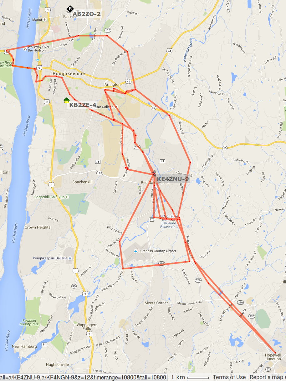
APRS tracks for my rides around Poughkeepsie in early November 2015:
APRS Coverage – Highland to Hopewell – 2015-11
Turning on the topo data and squinting at the Red Oaks Mill area:
APRS Coverage – Red Oaks Mill area topo – 2015-11
The topography isn’t in my favor, with two ridgelines between Red Oaks Mill and the two APRS nodes near Poughkeepsie. APRS coverage southwest of Red Oaks Mill along the Mighty Wappingers Creek (basically, Vassar Road) ranges from spotty to nonexistent, because that route has even worse topography.
Seems to me an APRSiGate in Red Oaks Mill, running Xastir (perhaps headless) on an RPi, conjured from my heap (perhaps with a shiny new TNC-Pi atop the RPi, rather than an ancient Kantronics KPC-9612), and using a vertical VHF antenna in the attic (because lightning), might improve the situation.
That whole project continues to slip into the future, but at least I have more motivation and linkies…
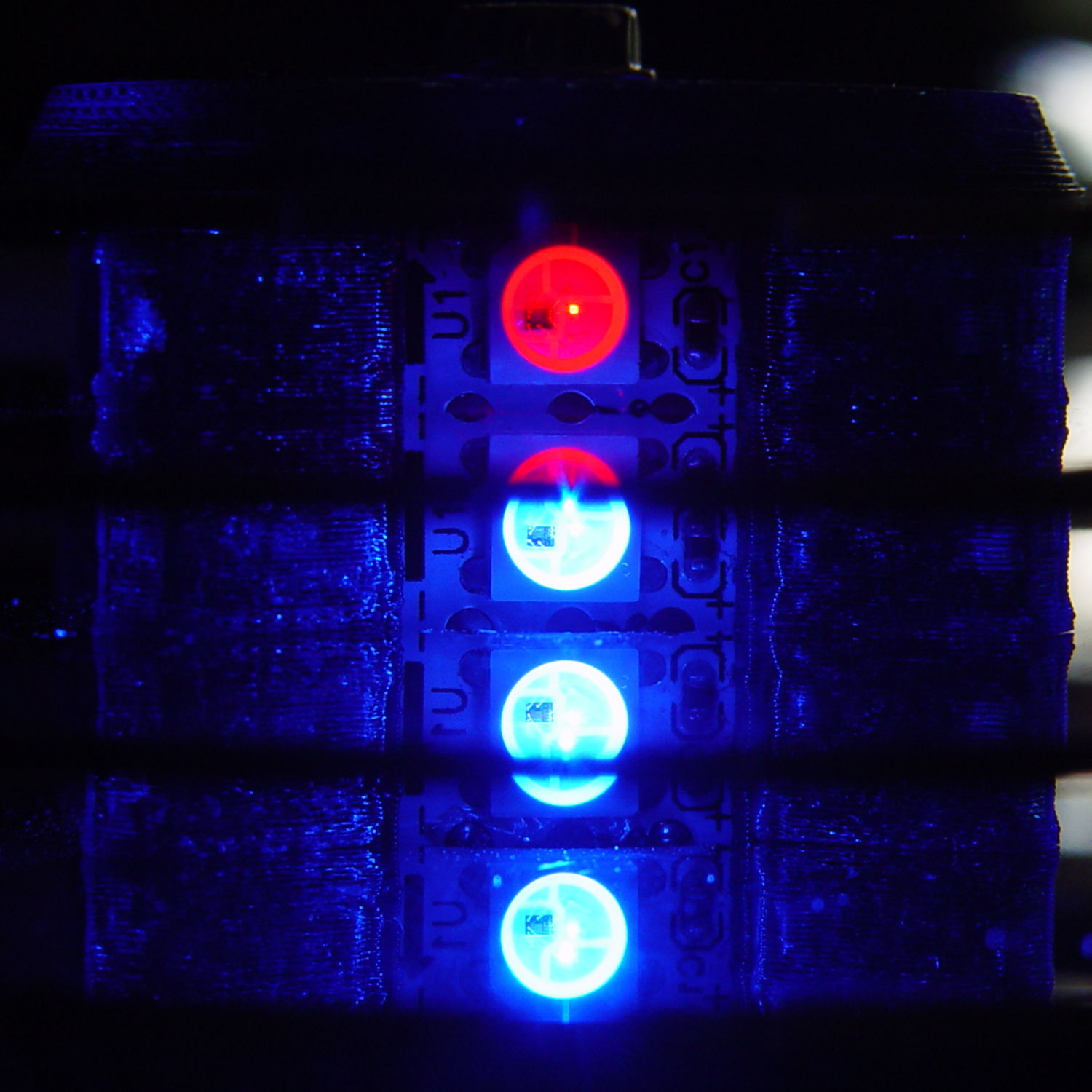
Just to show why powering Neopixels directly from an Arduino is a Bad Idea, I wired up an Adafruit Jewel thusly (and, BTW, exactly like their lead illustration shows):
Makes your skin crawl just to look at it, right?
With all seven Neopixels set to a gray PWM (64,64,64), the average current should be around 90 mA: 21 * 18 mA * 64/255, with another 6% knocked off because the WS2812B controller imposes that much mandatory dark time at PWM 255.
Eyeballometrically, this looks pretty close at 100 mA/div:
Neopixel current 100 mA – 64-64-64 0-7 200 mA peak
But those seven asynchronous PWM oscillators guarantee this will happen every now & again:
Neopixel current 100 mA – 64-64-64 0-7 400 mA peak
The 400 mA peaks happen when all seven Neopixels turn on at once. The broad flat floor means they’re off most of the time and the power supply sees a hefty 400 Hz pulsating load.
The bottom trace shows the effect of those peaks in the top trace (at 200 mA/div) on the Arduino’s VCC pin:
Neopixel current 200 mA – 64-64-64 0-7 400 mA pk w VCC
That’s at 200 mV/div and AC coupled to remove the 5 VDC supply. Because the board runs from USB power, the on-board regulator doesn’t contribute to the problem, but there’s plenty of problem to go around.
Always use an external power supply and a 5 VDC regulator with Neopixels!