-
Earplug Case
A no-assembly-needed earplug case from Printables will be more easily found in Mary’s purse than the previous small bag:
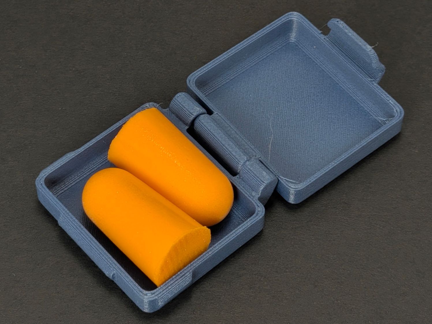
Earplug case That’s the “grippy bits” version of the model, which really is easier to open than the straight-sided version.
I printed a few more, loaded them with earplugs, and put them where they may come in handy. In retrospect, I should have used clear PETG to show off the retina-burn plugs.
Living in the future is great!
-
Subscribe
Subscribed
Already have a WordPress.com account? Log in now.
