-
Layered Paper: Masking the Cornell Painted Warblers
After getting better at aligning printed sheets for laser cuttery and learning how to use GIMP’s
Path Edittool, a pair of Cornell Painted Warblers emerged!We call this one “Happy Bird”:
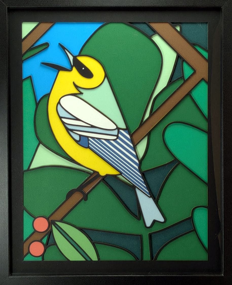
Cornell Warblers – page 5 And his companion “Pensive Bird”:
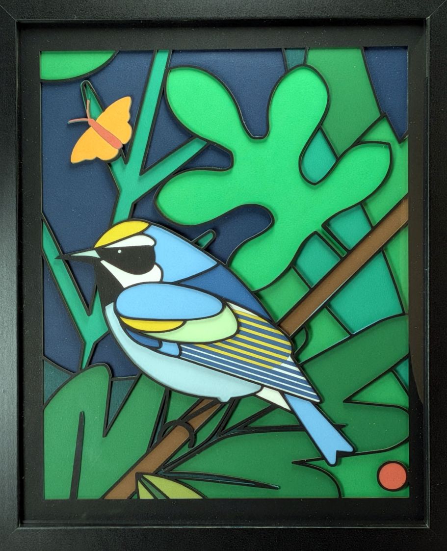
Cornell Warblers – page 4 The page numbers refer to the PDF file containing the outlines of all six birds.
The wing feathers and butterfly require finer resolution than the black mask layer allows, so the first layer is printed on white paper. I put the berries and nut-like objects on that layer, too, mostly to reduce the number of layers.
After considerable fumbling, it turns out GIMP provides a straightforward way to create the outlines required for the top Black Mask, from which all the other layers descend.
A closeup of Happy Bird’s head as imported into GIMP from the PDF at 300 DPI = 11.8 pixel/mm:
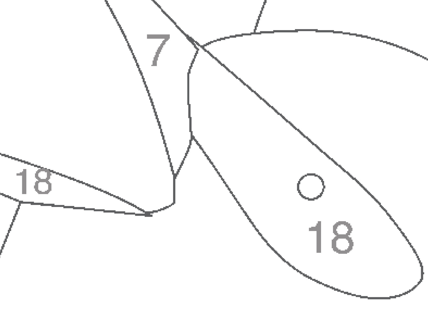
Page 5 – PDF line – detail Because the Cornell Warblers were intended as a paint-by-number project, the PDF has (gray) color numbers in (most of the) regions. Selecting the numbers with GIMP’s
Select by Colortool and hittingDeleteclears the region forBucket Fillcolors copied from the key sheet with theColor Pickertool: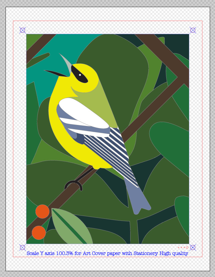
Page 5 – Inkscape print layout I cropped the images to emphasize the birds and scaled the result to fit the 8×10 inch frame size. The picture is 172×220 mm within the red 200×250 mm frame cut from Letter size sheets of Art Cover paper stock. The corner targets come into play while aligning the paper with the laser pattern.
Creating the Black Mask layer also starts from the cropped / scaled image. Select the black lines by color, then
Growthe selection by 7 pixels = 0.6 mm to make the selection about 1.5 mm wide: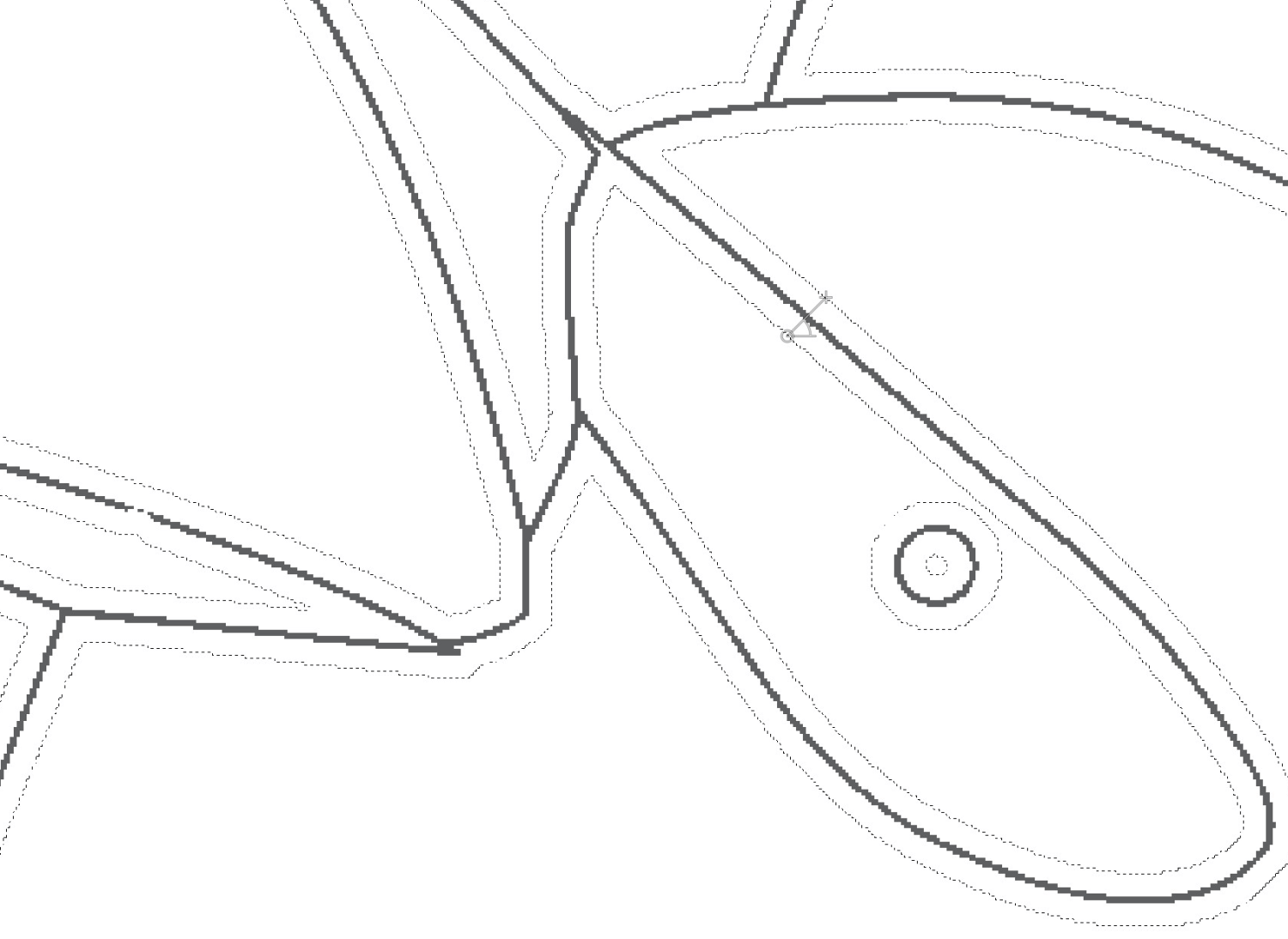
Page 5 – PDF line – 1.5mm selection Use
Quick Maskto edit the selection. For example, I reduced the eye to a cutout through the mask revealing the white spot on the printed layer: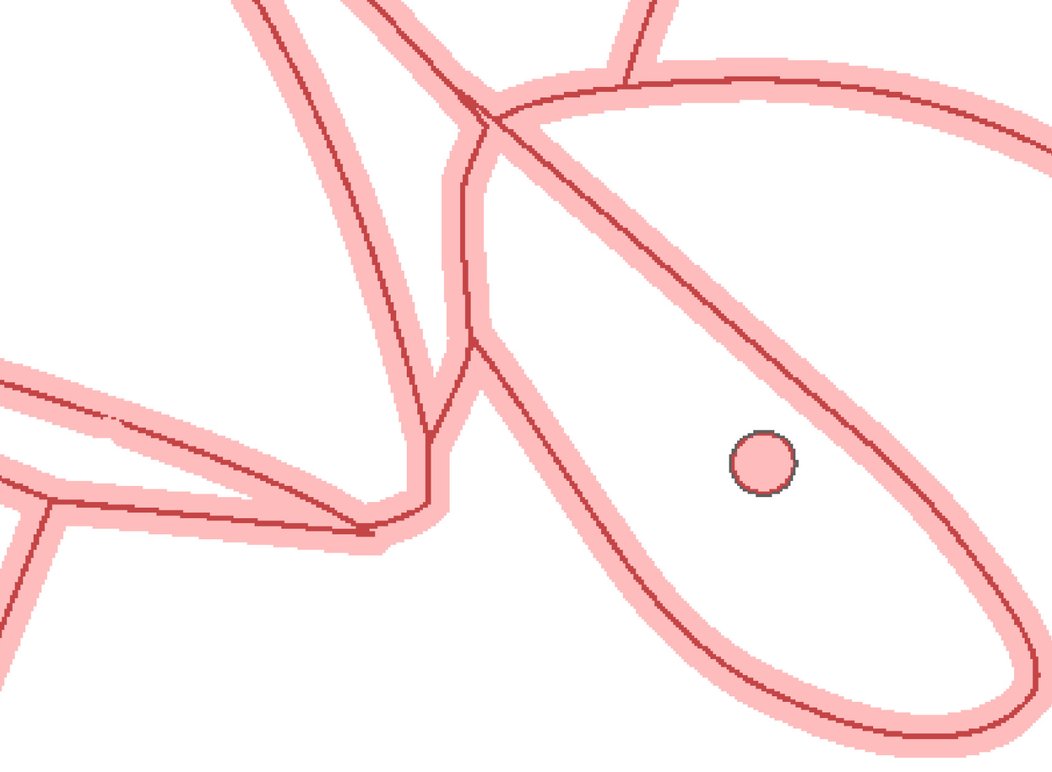
Page 5 – PDF line – inverted quick mask Eventually the selection will neatly bracket the borders between the colors:
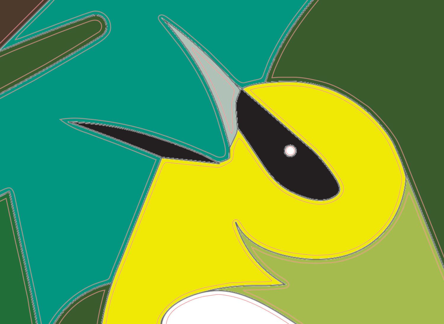
Page 5 – PDF line – fill colors – mask overlay The black legs and feet must be edited down to their original size, as became obvious on the first iteration:

Page 5 – Test piece – stack oblique view The fixed-up Quick Mask looks like this:
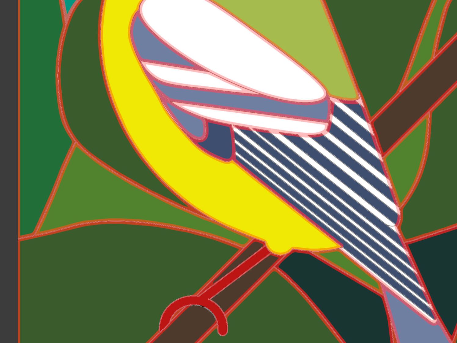
Page 5 – PDF line – selection – printed areas The mask includes a 6 pixel = 0.5 mm border line around the perimeter of the image which serves as the outer edge of the cut-out areas and helps match the selections to the image.
The process of growing & tweaking the selection will create orphan pixels:
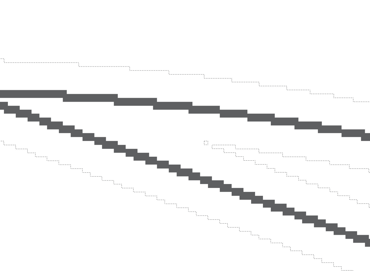
Page 5 – PDF line – orphan pixel selection Each orphan pixel becomes a tiny triangle when imported into LightBurn:
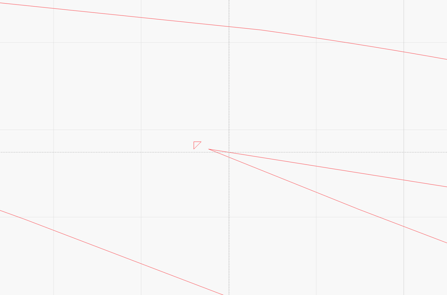
Page 5 – PDF line – orphan pixel – LighBurn vectors You’ll first notice those when the laser hesitates while cutting the outlines, which may overcook the adjacent paper. I cannot reliably detect these other than by watching the laser, because a single pixel is simply too small to see on-screen at normal zoom sizes. You can delete them in the LightBurn file or, if you prefer a single source of truth, in GIMP to regenerate the whole thing.
The end result of all this is a single, rather complex,
Selectionthat you must convert into aPath, which you then export to an SVG file and import into LightBurn for laser cuttery.Next: Aligning and layering
-
Subscribe
Subscribed
Have a WordPress.com account? Log in now.

