-
HQ Sixteen: Table Leveling Blocks
The Handi-Quilter HQ Sixteen rides on two tracks along the 11 foot length of the table, with an unsupported 8 foot span between the legs on each end:

HQ Sixteen – remounted handlebars in use Contemporary versions of the table have support struts in the middle that our OG version lacks and, as a result, our table had a distinct sag in the middle. During the course of aligning the table top into a plane surface with tapered wood shims, I discovered the floor was half an inch out of level between the table legs.
Now that the whole thing has settled into place, I measured the shim thicknesses and made tidy blocks to replace them:

HQ Sixteen – table shims – finished The OpenSCAD code has an array with the thickness and the number of blocks:
SHIM_THICK = 0;
SHIM_COUNT = 1;

Shims = [
    [3.5,1],
    [5.0,3],
    [6.0,2],
    [6.5,1],
    [7.0,1]
];
Yes, I call them “blocks” here and wrote “shims” in the code. A foolish consistency, etc.
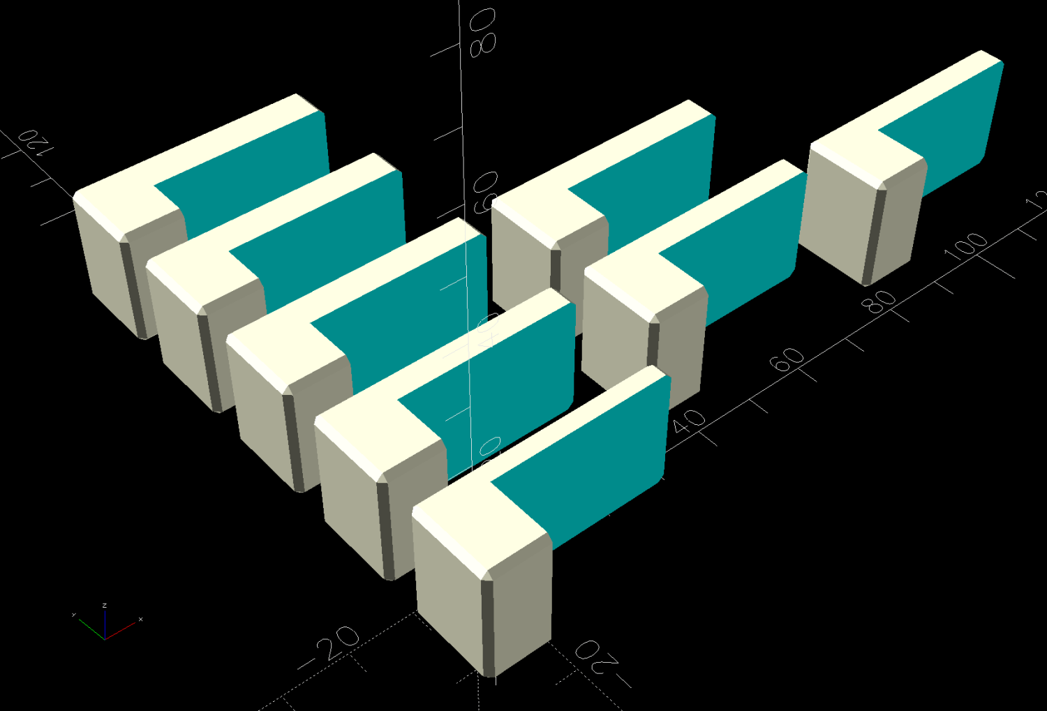
The model is a chamfered block with a chunk removed to leave a tongue of the appropriate thickness:

HQ Sixteen – table shims – solid model Building them with the label against the platform produces a nice nubbly surface:
HQ Sixteen – table shims – PrusaSlicer – bottom The labels print first and look lonely out there by themselves:
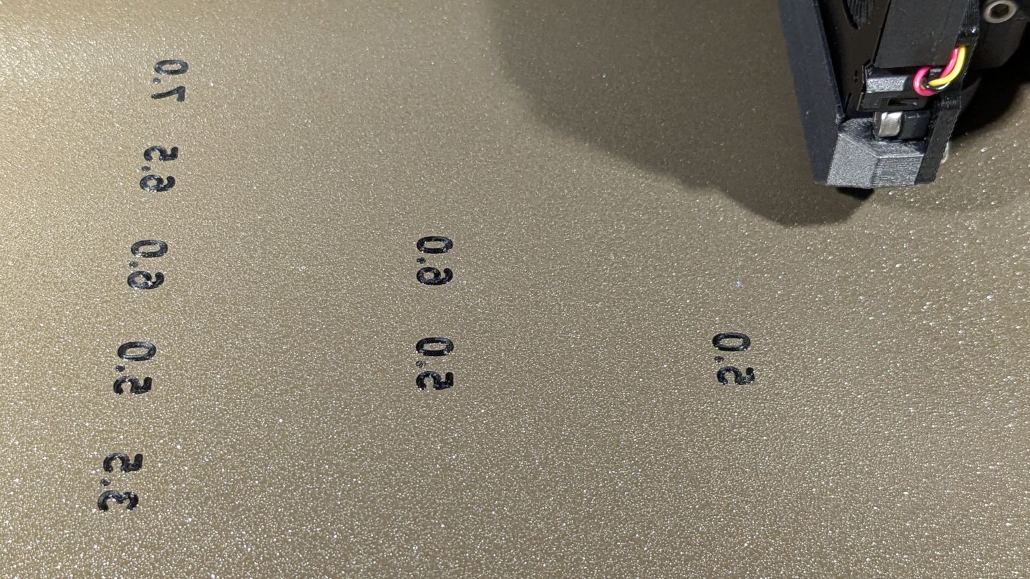
HQ Sixteen – table shims – legends The rest of the first layer fills in around the labels:

HQ Sixteen – table shims – first layer Putting the labels on the bottom makes the wipe tower only two layers tall and eliminates filament changes above those layers. Those eight blocks still took a little over three hours, because there’s a lot of perimeter wrapped around not much interior.
Having had the foresight to draw a sketch showing where each block would go, I slid one next to its wood shim, yanked the shim out, and declared victory:
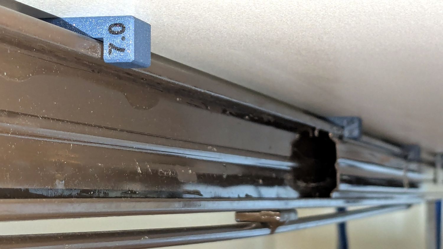
HQ Sixteen – table shims – installed The tension rod welded under the table rail prevents even more sag, but the struts under the new version of the table show other folks were unhappy with the sag of this one. Another leg or two seems appropriate.
With the table leveled and the surface aligned, the HQ Sixteen glides easily in all directions. The result isn’t perfect and Mary keeps the anchor block at hand, but the machine now displays much less enthusiasm for rolling toward the middle of the table.
The OpenSCAD source code as a GitHub Gist:
This file contains hidden or bidirectional Unicode text that may be interpreted or compiled differently than what appears below. To review, open the file in an editor that reveals hidden Unicode characters. Learn more about bidirectional Unicode characters// HQ Sixteen – table shims // Ed Nisley – KE4ZNU // 2025-02-27 include <BOSL2/std.scad> Layout = "Show"; // [Show,Build] /* [Hidden] */ SHIM_THICK = 0; SHIM_COUNT = 1; Shims = [ [3.5,1], [5.0,3], [6.0,2], [6.5,1], [7.0,1] ]; Block = [40.0,20.0,15.0]; // overall shim size Grip = 10.0; // … handle length BlockRadius = 1.0; // corner rounding / chamfer LabelThick = 0.4; LabelSize = 5.5; LabelFont = "Arial:style:Bold"; LabelColor = "Red"; Protrusion = 0.1; Gap = 5.0; //———- // Define shim shape module ShimBlock(Height = Shims[0][SHIM_THICK],Part="All") { if (Part == "Block" || Part == "All") difference() { left(Grip) cuboid(Block,anchor=BOTTOM + LEFT,chamfer=BlockRadius); up(Height) cube(Block + 2*[Protrusion,Protrusion,0],anchor=BOTTOM + LEFT); left(Grip/2 – BlockRadius/2) fwd(Block.y/2 – LabelThick) up(Block.z/2) xrot(90) zrot(-90) linear_extrude(height=LabelThick + Protrusion,convexity=20) text(text=format_fixed(Height,1),size=LabelSize,spacing=1.00, font=LabelFont,halign="center",valign="center"); } if (Part == "Text" || Part == "All") color(LabelColor) left(Grip/2 – BlockRadius/2) fwd(Block.y/2 – LabelThick) up(Block.z/2) xrot(90) zrot(-90) linear_extrude(height=LabelThick,convexity=20) text(text=format_fixed(Height,1),size=LabelSize,spacing=1.00, font=LabelFont,halign="center",valign="center"); } //———- // Build them all if (Layout == "Show") ShimBlock(); if (Layout == "Build") { for (j=[0:len(Shims)-1]) back(j*(Block.z + Gap)) for (i=[0:(Shims[j][SHIM_COUNT] – 1)]) right(i*(Block.x + Gap)) up(Block.y/2) xrot(90) ShimBlock(Shims[j][SHIM_THICK],Part="Block"); for (j=[0:len(Shims)-1]) back(j*(Block.z + Gap)) for (i=[0:(Shims[j][SHIM_COUNT] – 1)]) right(i*(Block.x + Gap)) up(Block.y/2) xrot(90) ShimBlock(Shims[j][SHIM_THICK],Part="Text"); }
-
Subscribe
Subscribed
Already have a WordPress.com account? Log in now.
