-
CNC-3018XL Setup: Table Riser Blocks
After fixing the X axis drive, the CNC-3018XL table moved properly again, so I measured its overall alignment:

3018CNC – table height measurement The +Y side (on the left in the photo, keeping in mind I’ve rotated the axes) turned out to be 0.7 mm too low, so I made a set of riser blocks to level the tabletop:

Table Riser – solid model The 10 mm height would ram the tip of a Pilot pen about 10 mm below the tabletop surface, were it not for the spring-loaded pen holder:

Pilot V5RT holder – installed The 0.7 mm difference in height levels the tabletop:

CNC3018XL – table riser positions The OpenSCAD code produces an SVG outline I intended to use for a foam pad, but then I found a quartet of springs that worked even better:
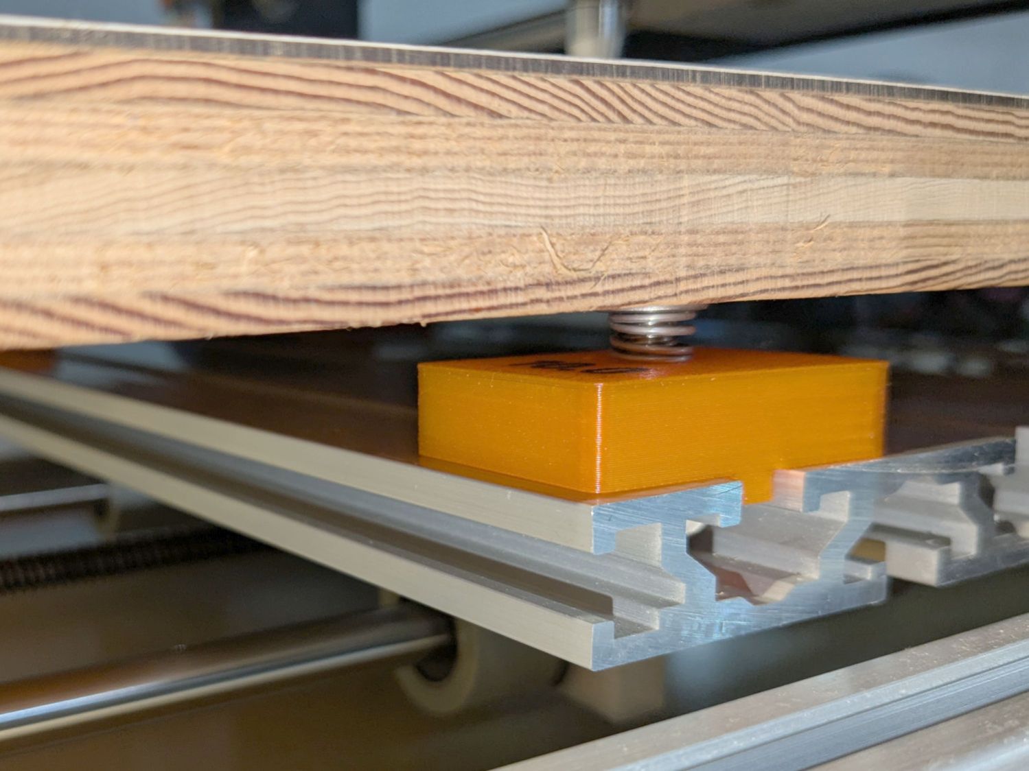
CNC3018XL – table spring mount So it’s now aligned within ±0.3-ish mm across the surface, with the unflatness of a slab cut from a 1955-era Formica kitchen countertop accounting for most of the difference in a swale from Quadrant III across the origin to Quadrant I.
Which a check plot using an old file shows will be Flat Enough for my simple needs:
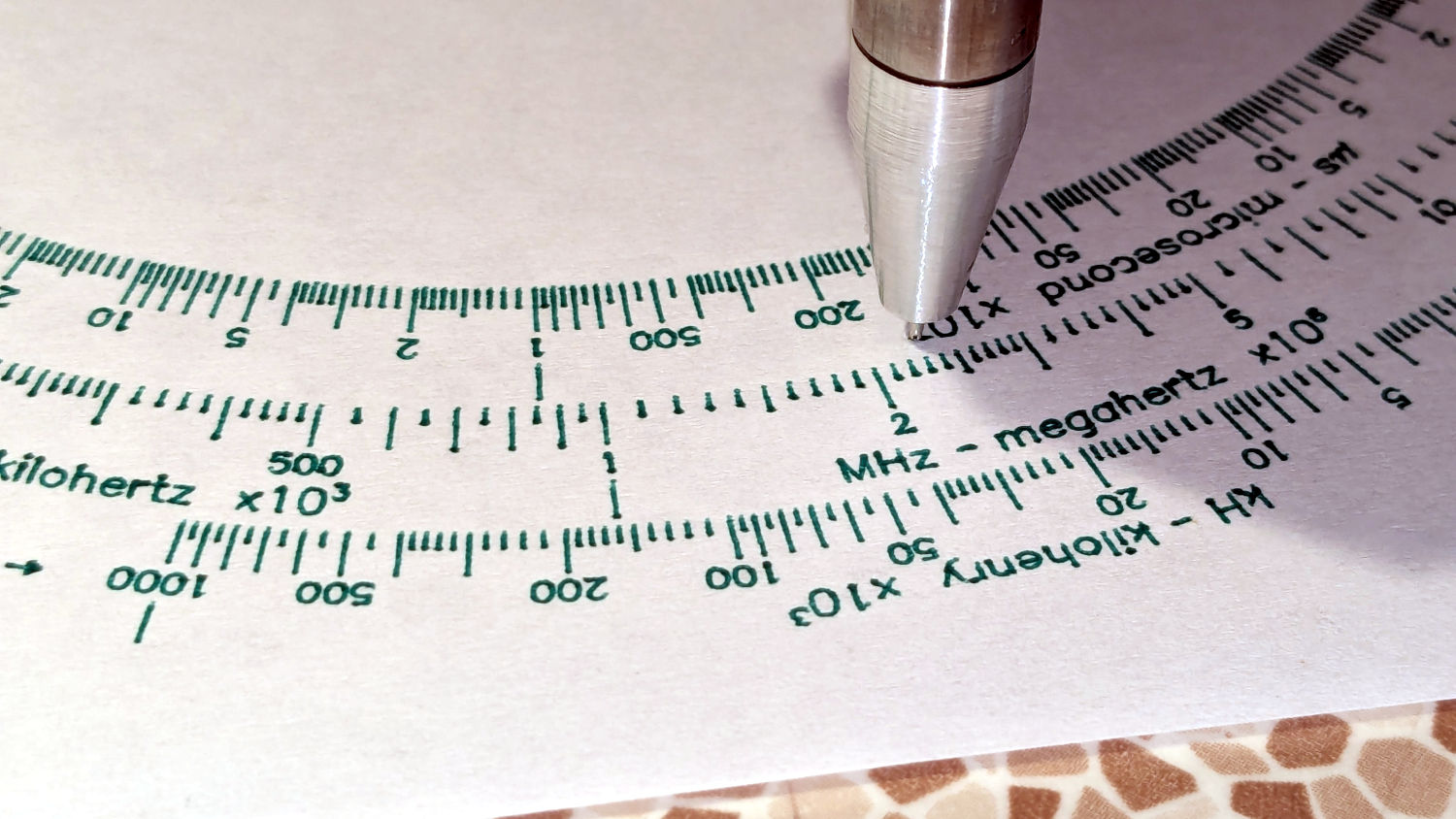
CNC3018XL – test plot Having the camera alignment remain exactly spot on came as a pleasant surprise:
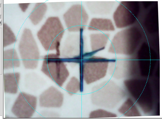
Camera Alignment check The faded cross to the left came from the table’s previous position; there’s no positive index between the countertop slab and the underlying T-slots.
Part of the motivation for these blocks was to verify PrusaSlicer automagically handles filament / color changes between two objects, as long as OpenSCAD hasn’t unioned them as part of a common transformation. Not having to cut out the socket around the text simplifies the code from what I’d been doing with previous objects.
The OpenSCAD source code as a GitHub Gist:
This file contains hidden or bidirectional Unicode text that may be interpreted or compiled differently than what appears below. To review, open the file in an editor that reveals hidden Unicode characters. Learn more about bidirectional Unicode characters// CNC 3018 table riser blocks // Ed Nisley – KE4ZNU // 2025-06-29 include <BOSL2/std.scad> Layout = "Show"; // [Show,Build,Outlines] /* [Hidden] */ HoleWindage = 0.2; Protrusion = 0.1; BlockOA = [40.0,30.0,10.0]; // riser block size SlotBlock = [8.0,BlockOA.y,3.0]; // alignment in slot BoltOD = 6.0 + HoleWindage; // central bolt LogoFont = "Fira Sans Condensed:style=SemiBold"; LogoSize = 7.5; LogoColor = "Red"; LogoThick = 0.4; //———- // Define Shapes module Riser(thick=1,matl="Block") { LogoText = format_fixed(thick,1); if (matl == "Text" || matl == "All") right(BlockOA.x/4) zrot(90) color(LogoColor) up(thick + SlotBlock.z + ((matl == "All") ? 0.01 : 0)) text3d(LogoText,LogoThick + ((matl == "All") ? 0.01 : 0),LogoSize,LogoFont, anchor=TOP,atype="ycenter"); if (matl == "Block" || matl == "All") difference() { cuboid(SlotBlock,$fn=8*3,anchor=BOTTOM,rounding=2.0,except=[BOTTOM,TOP]) position(TOP) cuboid(BlockOA,$fn=8*3,anchor=BOTTOM,rounding=2.0,except=[BOTTOM,TOP]); down(Protrusion) zrot(180/6) cyl(2*BlockOA.z,d=BoltOD,$fn=6,anchor=BOTTOM,circum=true); } } //———- // Build things if (Layout == "Show") down(SlotBlock.z) Riser(BlockOA.z,matl="All"); if (Layout == "Outlines") { projection(cut=false) Riser(BlockOA.z,matl="Block"); } if (Layout == "Build") { up(BlockOA.z + SlotBlock.z) xrot(180) Riser(BlockOA.z,matl="Block"); up(BlockOA.z + SlotBlock.z) xrot(180) Riser(BlockOA.z,matl="Text"); }
-
Subscribe
Subscribed
Already have a WordPress.com account? Log in now.
