-
Google Pixel 3a Microscope Adapter
Hand-holding my Google Pixel 3a phone over the microscope eyepiece worked well enough to justify building Yet Another Camera Adapter:

Pixel 3a Microscope Adapter – in action The solid model looks about like you’d expect:
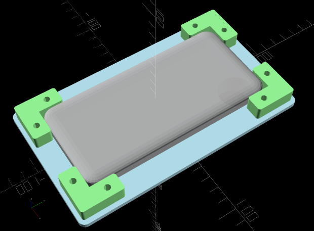
Google Pixel 3a Zoom Microscope Mount – solid model – top The “camera” actually has the outside dimensions of a Spigen case, rather than the bare phone, because dropping a bare phone is never a good idea.
The base plate pretty much fills the M2’s platform:

Pixel 3a Microscope Adapter – M2 platform I originally arranged the four corners around the plate to print everything in one go, but an estimated six hours of print time suggested doing the corners separately would maximize local happiness. Which it did, whew, even if the plate ran for a bit over 4-1/2 hours.
The snout is a loose fit around the 5× widefield microscope eyepiece, with the difference made up in a wrap of black tape; it’s much easier to adjust the fit upward than to bore out the snout. An overwrap of tape secures the snout to the eyepiece, which I’ve dedicated to the cause; the scope normally rocks 10× widefield glass.
The tapered hole exposes the phone’s fingerprint reader to simplify unlocking, should it shut down while I’m fiddling with something else.
The microscope doesn’t fully illuminate the camera’s entrance pupil at minimum zoom, with 4.5× filling the screen and (mostly) eliminating the vignette. The corner blocks have oversize holes to allow aligning the camera lens axis over the microscope optical axis. The solid model incorporates Lessons Learned from the version you see here, because you (well, I) can’t measure the camera axis with respect to the outside dimensions accurately enough:

Pixel 3a Microscope Adapter – installed – front Although it’s less unsteady than it looks, microscopy requires a gentle touch at the best of times. The adapter doesn’t add much wobble to the outcome:
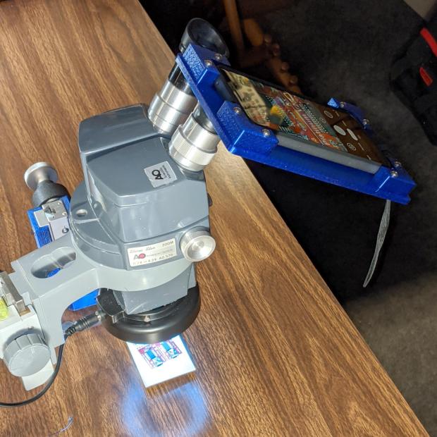
Pixel 3a Microscope Adapter – installed – side The field is about 14×19 mm with the camera at 4.5× and the microscope at minimum zoom:
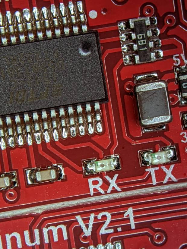
Pixel 3a Microscope Adapter – test image – min mag You can see a little darkening on the upper and lower right corners, so the phone’s still minutely leftward.
The field is about 1.5×2 mm at full throttle:
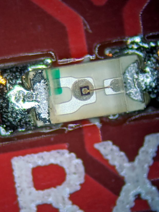
Pixel 3a Microscope Adapter – test image – max mag Color balance with the cold white LED ring isn’t the best, but it’s survivable. Mad props to OpenCamera for exposing All. The. Controls. you might possibly need.
The OpenSCAD source code as a GitHub Gist:
This file contains hidden or bidirectional Unicode text that may be interpreted or compiled differently than what appears below. To review, open the file in an editor that reveals hidden Unicode characters. Learn more about bidirectional Unicode characters// Google Pixel 3a mount for stereo zoom microscope // Ed Nisley – KE4ZNU – 2019-12 Layout = "Show"; // [Show,BuildAll,BuildBumpers,BuildPlate,DrillGuide,Phone,Plate,Bumper] /* [Hidden] */ ThreadThick = 0.25; ThreadWidth = 0.40; HoleWindage = 0.2; Protrusion = 0.1; // make holes end cleanly function IntegerMultiple(Size,Unit) = Unit * ceil(Size / Unit); ID = 0; OD = 1; LENGTH = 2; inch = 25.4; //———————- // Dimensions Phone = [74.5,156.0,12.0]; // inside Spigen case PhoneRadii = [10.0,10.0,3.0]; // corner rounding, likewise LensOffset = [-17.0,-18.5,0]; // looking at phone screen, (-) sign = from right/top edge PrintReader = [0,Phone.y/2 – 44.0,0]; // fingerprint reader from center PrintReaderDia = [20.0,30.0,0]; // … hole for access Eyepiece = [11.5,28.0 + 0.50,27.0]; // ID = lens, OD includes clearance Insert = [3.0,4.5,4.0]; // M3 threaded brass insert Screw = [3.0,7.0,3.5]; // OD = washer, LENGTH = washer + head height WallThick = 3.0; // minimum wall thickness Bumper = [2*Screw[OD],20.0,Phone.z]; // bumper edge piece BumperOAL = Bumper.y + Bumper.x; // outside length for corner piece BumperRadius = 2.0; MinMargin = 1.2*Bumper.x; // at least this much extra plate for bumpers echo(str("MinMargin: ",MinMargin)); Plate = [IntegerMultiple(Phone.x + 2*MinMargin,5.0), IntegerMultiple(Phone.y + 2*MinMargin,5.0), false ? 3*ThreadThick : max(Insert[LENGTH] + 2*ThreadThick,WallThick)]; PlateRadius = 5.0; echo(str("Plate: ",Plate," radius: ",PlateRadius)); EmbossDepth = 2*ThreadThick + Protrusion; DebossHeight = EmbossDepth; ScrewOffset = Bumper.x/2; ScrewAdjust = 1.5*Screw[ID]; NumSides = 2*3*4; Gap = 2.0; // between build layout parts //———————- // Useful routines module PolyCyl(Dia,Height,ForceSides=0) { // based on nophead's polyholes Sides = (ForceSides != 0) ? ForceSides : (ceil(Dia) + 2); FixDia = Dia / cos(180/Sides); cylinder(r=(FixDia + HoleWindage)/2, h=Height, $fn=Sides); } // Basic shapes // Overall phone outline module Phone() { hull() for (i=[-1,1], j=[-1,1], k=[-1,1]) translate([i*(Phone.x/2 – PhoneRadii.x),j*(Phone.y/2 – PhoneRadii.y),k*(Phone.z/2 – PhoneRadii.z)]) resize(2*PhoneRadii) sphere(r=1,$fn=NumSides); } module Plate() { union() { difference() { union() { hull() for (i=[-1,1], j=[-1,1]) translate([i*(Plate.x/2 – PlateRadius),j*(Plate.y/2 – PlateRadius),0]) cylinder(r=PlateRadius,h=Plate.z,center=true,$fn=NumSides); translate([Phone.x/2,Phone.y/2,-Eyepiece[LENGTH]/3 + Plate.z/2] + LensOffset) cylinder(d=Eyepiece[OD] + 2*WallThick,h=Eyepiece[LENGTH]/3, center=false,$fn=NumSides); translate([Phone.x/2,Phone.y/2,-2*Eyepiece[LENGTH]/3 + Plate.z/2 + Protrusion] + LensOffset) cylinder(d1=Eyepiece[OD] + 10*ThreadThick, d2=Eyepiece[OD] + 2*WallThick, h=Eyepiece[LENGTH]/3, center=false,$fn=NumSides); } translate([Phone.x/2,Phone.y/2,-2*Eyepiece[LENGTH] + Plate.z/2 + Protrusion] + LensOffset) PolyCyl(Eyepiece[OD],2*Eyepiece[LENGTH],NumSides); translate(PrintReader + [0,0,-Plate.z/2 – Protrusion]) cylinder(d1=PrintReaderDia[OD],d2=PrintReaderDia[ID],h=Plate.z + 2*Protrusion,$fn=NumSides); for (i=[-1,1], j=[-1,1]) translate([i*(Phone.x/2 + Bumper.x/2),j*(Phone.y/2 – Bumper.y/2),-Plate.z]) PolyCyl(Insert[OD],2*Plate.z,8); for (i=[-1,1], j=[-1,1]) translate([i*(Phone.x/2 – Bumper.y/2),j*(Phone.y/2 + Bumper.x/2),-Plate.z]) PolyCyl(Insert[OD],2*Plate.z,8); translate([0,-12,Plate.z/2]) // recess for legend cube([55,40,EmbossDepth],center=true); } translate([0,0,Plate.z/2 – EmbossDepth]) linear_extrude(height=DebossHeight,convexity=20) text(text="Pixel 3a",size=6,spacing=1.20, font="Arial:style:Bold",halign="center",valign="center"); translate([0,-15,Plate.z/2 – EmbossDepth]) linear_extrude(height=DebossHeight,convexity=20) text(text="Ed Nisley",size=6,spacing=1.20, font="Arial:style:Bold",halign="center",valign="center"); translate([0,-25,Plate.z/2 – EmbossDepth]) linear_extrude(height=DebossHeight,convexity=20) text(text="softsolder.com",size=4,spacing=1.20, font="Arial:style:Bold",halign="center",valign="center"); } } module BumperPiece() { difference() { translate([0,-BumperOAL/2 + Bumper.x,0]) hull() for (i=[-1,1], j=[-1,1]) translate([i*(Bumper.x/2 – BumperRadius),j*(BumperOAL/2 – BumperRadius),0]) cylinder(r=BumperRadius,h=Bumper.z,center=true,$fn=NumSides); translate([0,-Bumper.y/2,-Bumper.z]) PolyCyl(ScrewAdjust,2*Bumper.z,8); } } // Side bumpers, XY origin at inner corner module BumperCorner() { union() { translate([Bumper.x/2,0,0]) BumperPiece(); translate([0,Bumper.x/2,0]) rotate(-90) BumperPiece(); } } //- Build things if (Layout == "Phone") Phone(); if (Layout == "Plate") Plate(); if (Layout == "Bumper") BumperCorner(); if (Layout == "Show") { color("LightBlue") Plate(); for (i=[-1,1], j=[-1,1]) { a = i > 0 && j > 0 ? 0 : i < 0 && j > 0 ? 90 : i > 0 && j < 0 ? -90 : 180 ; translate([i*Phone.x/2,j*Phone.y/2,Plate.z/2 + Bumper.z/2]) rotate(a) color("LightGreen") BumperCorner(); translate([0,0,Phone.z/2 + Plate.z/2 + Protrusion]) color("DarkGray",0.5) Phone(); } } if (Layout == "BuildAll") { translate([0,0,Plate.z/2]) rotate([0,180,0]) Plate(); for (i=[-1,1], j=[-1,1]) { a = i > 0 && j > 0 ? 0 : i < 0 && j > 0 ? 90 : i > 0 && j < 0 ? -90 : 180 ; translate([i*(Plate.x/2 + Gap),j*(Plate.y/2 + Gap),Bumper.z/2]) rotate(a) BumperCorner(); } } if (Layout == "BuildPlate") { translate([0,0,Plate.z/2]) rotate([0,180,0]) Plate(); } if (Layout == "BuildBumpers") { for (i=[-1,1], j=[-1,1]) { a = i > 0 && j > 0 ? 180 : i < 0 && j > 0 ? -90 : i > 0 && j < 0 ? 90 : 0 ; translate([i*(Bumper.x + Gap),j*(Bumper.x + Gap),Bumper.z/2]) rotate(a) BumperCorner(); } } if (Layout == "DrillGuide") { projection(cut=true) Plate(); }
-
Subscribe
Subscribed
Have a WordPress.com account? Log in now.

