-
Discrete-transistor LM3909 LED Flasher
I’ve been using not-dead-yet lithium batteries to power astable multivibrators blinking LEDs on the red-to-yellow end of the spectrum, because the over-discharge protection circuitry in the batteries shuts down at 2.5 V, while not eking much light from LEDs toward the blue end of the spectrum.
Back in the late 60s, when integrated circuits were new, National Semiconductor designed and, in the early 70s, introduced the LM3909: “a monolithic oscillator specifically designed to flash Light Emitting Diodes”. The IC used an electrolytic capacitor as both timing element and voltage booster by charging the cap, then switching it in reverse series with the LED, to produce a voltage drop larger than the 1.5 V battery supply. The original National Semiconductor LM3909 datasheet will get you started and Application Note 154 gives more details and insight.
Rob Paisley’s work from 2008 suggested a discrete-transistor version might look just as attractive, in a techie sort of way, as the astables, and perhaps boost the 2 V from a pair of not-dead-yet alkaline cells high enough to light a blue LED.
Some LTSpice twiddling produces a suitable circuit:
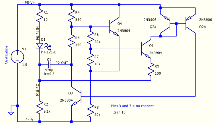
Discrete LM3909 – basic circuit The labeled nodes correspond to pin numbers on the IC package, with a suffix indicating what they did for a living. R2 combines the two timing resistors in the IC into a single unit, so “P18-RC” combines the pins. The Q2 pair over on the right forms a current mirror driving Q3, which the doc calls the “power transistor”, to yank the positive end of the capacitor to ground to light the LED.
The LED is faked by a PT-121-B diode with a 2.34 V forward drop at 20 mA. It’s rated for 20 A average current, so it’s not a particularly good model for a piddly 5 mm LED, but I’ll define it to be Good Enough for now.
Running the simulation at 1.5 V is encouraging:

Discrete LM3909 – basic circuit – 1.5 V simulation The green trace gives the voltage across the capacitor. Under these conditions, the voltage stays positive, although not by much.
Running it from a 3 V supply changes the results:

Discrete LM3909 – basic circuit – 3.0 V simulation The cap charges to about the same voltage, but the pulse now lasts long enough to charge it nearly half a volt in the wrong direction. This is Bad Practice, even though my similarly offending astables have been doing it for years.
The data sheet points out that the forward drops of Q1 and Q2 determine the trigger level for the start of the LED pulse, so adding another forward-biased junction in series should let the cap charge to a higher voltage and, for the same pulse duration, pull the low end up above zero to increase overall happiness.
-
Subscribe
Subscribed
Have a WordPress.com account? Log in now.

