-
Tek Circuit Computer: 3D Printed Cursor Milling Fixture
The original Tektronix Circuit Computer cursor was probably die-cut from a larger sheet carrying pre-printed hairlines:

Tek CC – genuine – detail Machining a punch-and-die setup lies well beyond my capabilities, particularly given the ahem anticipated volume, so milling seems the only practical way to produce a few cursors.
Attaching a cursor blank to a fixture with sticky tape showed that the general idea worked reasonably well:

Tek CC – Cursor blank on fixture However, the tape didn’t have quite enough griptivity to hold the edges completely flat against milling forces (a downcut bit might have worked better) and I found myself chasing the cutter with a screwdriver to hold the cursor in place. Worse, the tape’s powerful attraction to swarf made it a single-use item.
Some tinkering showed a single screw in the (pre-drilled) pivot hole, without adhesive underneath, lacked enough oomph to keep the far end of the cursor in place, which meant I had to think about how to hold it down with real clamps.
Which, of course, meant conjuring a fixture from the vasty digital deep. The solid model includes the baseplate, two cutting templates, and a clamping fixture for engraving the cursor hairline:
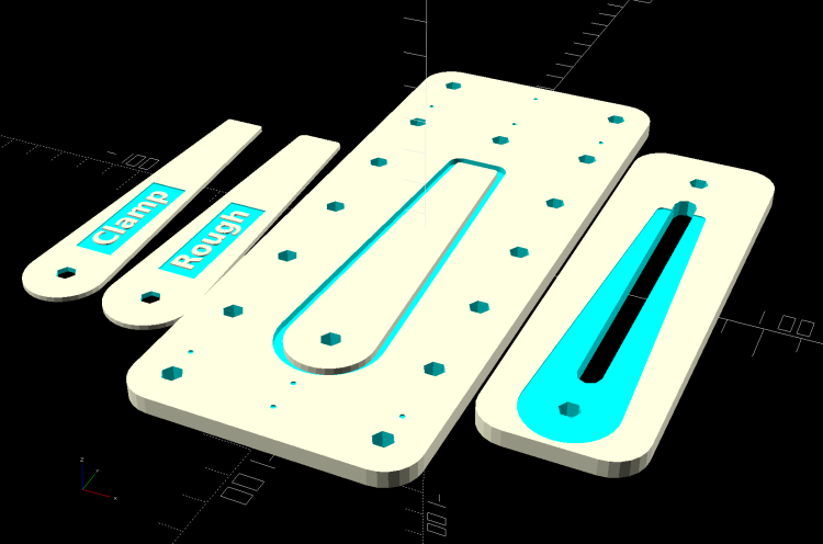
Cursor Fixture – build layout The perimeter of the Clamp template on the far left is 0.5 mm inside the cursor perimeter. Needing only one Clamp, I could trace it on a piece of acrylic, bandsaw it pretty close, introduce it to Mr Belt Sander for final shaping, and finally drill the hole:

Tek CC Cursor Fixture – clamp drilling The Rough template is 1.0 mm outside the cursor perimeter, so I can trace those outlines on a PET sheet:
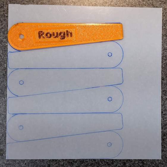
Tek CC Cursor Fixture – Rough template layout Then cut the patterns with a scissors, stack ’em up, and tape the edges to keep them aligned:

TekCC Cursor Fixture – Rough template Align the stack by feel, apply the Clamp to hold them in place, and secure the stack with a Sherline clamp:

Tek CC Cursor Fixture – outline rear clamp The alert reader will note it’s no longer possible to machine the entire perimeter in one pass; more on that in a while.
The baseplate pretty much fills the entire Sherline tooling plate. It sports several alignment pips at known offsets from the origin at the center of the pivot hole:

Tek CC Cursor Fixture – touch-off point Dropping the laser alignment dot into a convenient pip, then touching off X and Y to the known offset sets the origin without measuring anything. Four screws in the corners align the plate well enough to not worry about angular tweakage.
The OpenSCAD source code as a GitHub Gist:
This file contains hidden or bidirectional Unicode text that may be interpreted or compiled differently than what appears below. To review, open the file in an editor that reveals hidden Unicode characters. Learn more about bidirectional Unicode characters// Machining fixtures for Tek Circuit Computer cursor // Ed Nisley KE4ZNU Jan 2021 Layout = "Show"; // [Show, Build, Cursor, Clamp, Rough, Engrave] /* [Hidden] */ ThreadThick = 0.25; ThreadWidth = 0.40; HoleWindage = 0.2; Protrusion = 0.1; // make holes end cleanly inch = 25.4; function IntegerMultiple(Size,Unit) = Unit * ceil(Size / Unit); module PolyCyl(Dia,Height,ForceSides=0) { // based on nophead's polyholes Sides = (ForceSides != 0) ? ForceSides : (ceil(Dia) + 2); FixDia = Dia / cos(180/Sides); cylinder(d=(FixDia + HoleWindage),h=Height,$fn=Sides); } //———————- // Dimensions CursorHubOD = 1.0*inch; // original Tek CC was hard inch! CursorTipWidth = (9.0/16.0)*inch; CursorTipRadius = (1.0/16.0)*inch; CursorThick = 0.5; // plastic sheet thickness CutterOD = 3.175; // milling cutter dia CutterDepth = 2.0; // … depth of cut CutterLip = 0.5; // … clearance under edge ScribeOD = 3.0; // diamond scribe shank StudOC = [1.16*inch,1.16*inch]; // Sherline tooling plate grid StudClear = 5.0; // … screw clearance StudWasher = 11.0; // … washer OD CursorOffset = [-2*StudOC.x,0,0]; // hub center relative to fixture center // must have even multiples of stud spacing to put studs along centerlines BasePlateStuds = [6*StudOC.x,2*StudOC.y]; // fixture screws echo(str("Stud spacing: ",StudOC)); CornerRad = 10.0; // corner radius BasePlate = [2*StudWasher + BasePlateStuds.x,2*StudWasher + BasePlateStuds.y,5.0]; echo(str("Base Plate: ",BasePlate)); EngravePlate = [5*StudOC.x,1.5*StudOC.y,BasePlate.z]; echo(str("Engrave Plate: ",EngravePlate)); TemplateThick = 6*ThreadThick; LegendThick = 2*ThreadThick; Gap = 3.0; //———————- // Import SVG of cursor outline // Requires our hub OD to match reality // Hub center at origin module CursorSVG(t=CursorThick,od=0) { hr = CursorHubOD/2; translate([-hr,-hr,0]) linear_extrude(height=t,convexity=3) offset(r=od/2) import(file="/mnt/bulkdata/Project Files/Tektronix Circuit Computer/Firmware/TekCC-Cursor-Mark.svg",center=false); } //———————- // Milling fixture for cursor blanks module Fixture() { difference() { hull() // basic plate shape for (i=[-1,1], j=[-1,1]) translate([i*(BasePlate.x/2 – CornerRad),j*(BasePlate.y/2 – CornerRad),0]) cylinder(r=CornerRad,h=BasePlate.z,$fn=24); translate(CursorOffset + [0,0,BasePlate.z – CutterDepth]) difference() { CursorSVG(CutterDepth + Protrusion,1.5*CutterOD); CursorSVG(CutterDepth + Protrusion,-CutterLip); } translate(CursorOffset + [0,0,BasePlate.z – 2*ThreadThick]) { // alignment pips for (x=[-20.0,130.0], y=[-30.0,0.0,30.0]) translate([x,y,0]) cylinder(d=4*ThreadWidth,h=1,$fn=6); for (x=[-30.0,130.0,150.0]) translate([x,0,0]) cylinder(d=4*ThreadWidth,h=1,$fn=6); } for (i=[-1,1], j=[-1,1]) // mounting stud holes translate([i*BasePlateStuds.x/2,j*BasePlateStuds.y/2,-Protrusion]) rotate(180/6) PolyCyl(StudClear,BasePlate.z + 2*Protrusion,6); translate(CursorOffset + [0,0,-Protrusion]) // hub clamp hole rotate(180/6) PolyCyl(StudClear,BasePlate.z + 2*Protrusion,6); translate([2*StudOC.x,0,-Protrusion]) // tip clamp hole rotate(180/6) PolyCyl(StudClear,BasePlate.z + 2*Protrusion,6); for (i=[-2:2], j=[-1,1]) // side clamp holes translate([i*StudOC.x,j*StudOC.y,-Protrusion]) rotate(180/6) PolyCyl(StudClear,BasePlate.z + 2*Protrusion,6); } } //———————- // Show-n-Tell cursor module Cursor() { difference() { CursorSVG(CursorThick,0.0); translate([0,0,-Protrusion]) rotate(180/6) PolyCyl(StudClear,TemplateThick + 2*Protrusion,6); } } //———————- // Template for rough-cutting blanks module Rough() { bb = [40,12,LegendThick]; difference() { CursorSVG(TemplateThick,1.0); translate([0,0,-Protrusion]) rotate(180/6) PolyCyl(StudClear,TemplateThick + 2*Protrusion,6); difference() { translate([bb.x/2 + CursorHubOD/2,0,TemplateThick – bb.z/2 + Protrusion]) cube(bb + [0,0,Protrusion],center=true); translate([bb.x/2 + CursorHubOD/2,0,TemplateThick – bb.z]) linear_extrude(height=bb.z,convexity=10) text(text="Rough",size=7,spacing=1.00,font="DejaVu Sans:style:Bold",halign="center",valign="center"); } } } //———————- // Template for aluminium clamping plate module Clamp() { bb = [40,12,LegendThick]; difference() { CursorSVG(TemplateThick,-1.0); translate([0,0,-Protrusion]) rotate(180/6) PolyCyl(StudClear,TemplateThick + 2*Protrusion,6); difference() { translate([bb.x/2 + CursorHubOD/2,0,TemplateThick – bb.z/2 + Protrusion]) cube(bb + [0,0,Protrusion],center=true); translate([bb.x/2 + CursorHubOD/2,0,TemplateThick – bb.z]) linear_extrude(height=bb.z,convexity=10) text(text="Clamp",size=7,spacing=1.00,font="DejaVu Sans:style:Bold",halign="center",valign="center"); } } } //———————- // Engraving clamp module Engrave() { difference() { hull() // clamp outline for (i=[-1,1], j=[-1,1]) translate([i*(EngravePlate.x/2 – CornerRad),j*(EngravePlate.y/2 – CornerRad),0]) cylinder(r=CornerRad,h=EngravePlate.z,$fn=24); translate(CursorOffset + [0,0,-Protrusion]) CursorSVG(CursorThick + Protrusion,0.5); // pocket for blank cursor translate(CursorOffset + [0,0,-Protrusion]) rotate(180/6) PolyCyl(StudClear,EngravePlate.z + 2*Protrusion,6); translate([2*StudOC.x,0,-Protrusion]) rotate(180/6) PolyCyl(StudClear,EngravePlate.z + 2*Protrusion,6); hull() { for (i=[-1,1]) translate([i*1.5*StudOC.x,0,-Protrusion]) PolyCyl(2*ScribeOD,EngravePlate.z + 2*Protrusion,8); } } } //———————- // Build it if (Layout == "Cursor") { Cursor(); } if (Layout == "Clamp") { Clamp(); } if (Layout == "Rough") { Rough(); } if (Layout == "Engrave") { Engrave(); } if (Layout == "Show") { Fixture(); color("Green",0.3) translate(CursorOffset + [0,0,BasePlate.z + Protrusion]) Cursor(); color("Orange") translate(CursorOffset + [0,0,BasePlate.z + 10]) Rough(); color("Brown") translate(CursorOffset + [0,0,BasePlate.z + 20]) Clamp(); color("Gold") translate(0*CursorOffset + [0,0,BasePlate.z + 40]) Engrave(); } if (Layout == "Build"){ rotate(90) { Fixture(); translate([0,-((BasePlate.y + EngravePlate.y)/2 + Gap),EngravePlate.z]) rotate([180,0,0]) Engrave(); translate(CursorOffset + [0,(BasePlate.y + CursorHubOD)/2 + Gap,0]) Rough(); translate(CursorOffset + [0,(BasePlate.y + 3*CursorHubOD)/2 + 2*Gap,0]) Clamp(); } } The original doodle with some notions and dimensions that didn’t survive contact with reality:
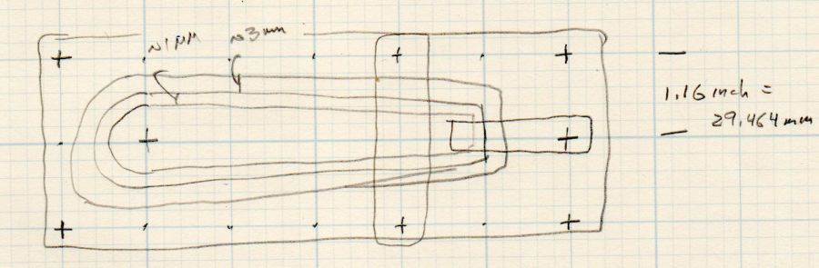
Cursor Fixture doodle I have no idea why the Sherline tooling plate has a 10-32 screw grid on 1.16 inch = 29.46 mm centers, but there they are.
-
Subscribe
Subscribed
Have a WordPress.com account? Log in now.

