-
CNC-3018XL: Improved X-Axis Home Switch Mount
A few months of inactivity left the CNC-3018XL table parked in its homed position where the gentle-but-inexorable pressure of the switch lever displaced the foam holding the plastic actuator tab on the X-axis bearing enough that it would no longer operate reliably:
3018 CNC – Y axis endstop Putting foam tape in a highly leveraged position produces the same poor results as in finance.
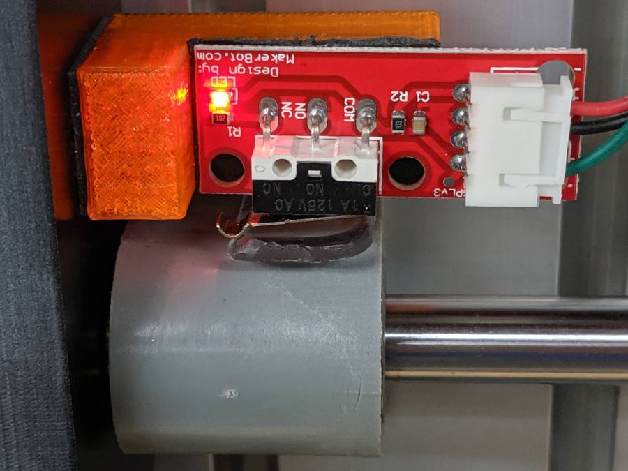
The fix requires reorienting the switch so a solid block on the bearing can push directly on the actuator lever:

CNC-3018 X Home Switch – bottom view The block must curve around the bearing to give the tape enough surface area for a good grip:

CNC-3018 X Home Switch – oblique view The solid model for the new X-axis mount looks about like you’d expect:

CNC-3018 X Home Switch Mount – solid model I increased the home switch pulloff to 2 mm, although it’s not clear that will make any difference in the current orientation.
The OpenSCAD source code as a GitHub Gist:
This file contains hidden or bidirectional Unicode text that may be interpreted or compiled differently than what appears below. To review, open the file in an editor that reveals hidden Unicode characters. Learn more about bidirectional Unicode characters// 3018-Pro Mount for Makerbot Endstop PCB // Ed Nisley KE4ZNU – 2019-07 (using OEM machine axes) // 2022-02-02 rotate X block (after renaming axes to match new layout) /* [Build Options] */ Layout = "Show"; // [Build, Show] /* [Hidden] */ ThreadThick = 0.25; // [0.20, 0.25] ThreadWidth = 0.40; // [0.40] function IntegerMultiple(Size,Unit) = Unit * ceil(Size / Unit); Protrusion = 0.01; // [0.01, 0.1] HoleWindage = 0.2; ID = 0; OD = 1; LENGTH = 2; //- Shapes // Basic PCB with hole for switch pins // origin at switch actuator corner, as seen looking at component side SwitchClear = [15.0,5.0,2.0]; // clearance around switch pins SwitchOffset = [12.5,9.0,0.0]; // center of switch pins from actuator corner PCB = [26.0,16.4,2*SwitchClear.z]; // switch PCB beyond connector, pin height //XBlock = [PCB.x + 10.0,PCB.y,20.0]; XBlock = [PCB.x,PCB.y,10.0]; XBearing = [10.0,26.5,28.5]; XPin = [10.0,20.0,10.0]; module XMount() { if (false) // side-push switch tended to slip difference() { translate([-10.0,0,0]) cube(XBlock,center=false); translate([0,-Protrusion,10.0]) cube(XBlock + [0,2*Protrusion,0],center=false); translate(SwitchOffset + [0,0,10.0 – SwitchClear.z/2]) cube(SwitchClear + [0,0,Protrusion],center=true); } else { difference() { cube(XBlock,center=false); translate(SwitchOffset + [0,0,XBlock.z – SwitchClear.z/2]) cube(SwitchClear + [0,0,Protrusion],center=true); } translate([1.25*XBlock.x,0,0]) difference() { cube(XPin + [0,0,XBearing[OD]/4],center=false); translate([-Protrusion,XPin.y/2,XPin.z + XBearing[OD]/2]) rotate([0,90,0]) cylinder(d=XBearing[OD],h=XPin.x + 2*Protrusion,center=false); translate([-Protrusion,-XPin.y/2,XPin.z]) cube(XPin + [2*Protrusion,0,0],center=false); } } } YBlock = [PCB.x,PCB.y,5.0]; module YMount() { difference() { cube(YBlock,center=false); translate(SwitchOffset + [0,0,YBlock.z – SwitchClear.z/2]) cube(SwitchClear + [0,0,Protrusion],center=true); } } ZBlock = [PCB.x,PCB.y,6.0]; ZPin = [20.0,10.0,5.5]; module ZMount() { difference() { cube(ZBlock,center=false); translate(SwitchOffset + [0,0,ZBlock.z – SwitchClear.z/2]) cube(SwitchClear + [0,0,Protrusion],center=true); } translate([1.25*ZBlock.x,0,0]) difference() { cube(ZPin,center=false); translate([ZPin.x/2,-Protrusion,4.0]) cube(ZPin + [0,2*Protrusion,0],center=false); } } //- Build things if (Layout == "Show") { translate([0,XBlock.y,0]) YMount(); translate([0,-XBlock.y/2]) XMount(); translate([0,-(ZBlock.y + XBlock.y)]) ZMount(); }
-
Subscribe
Subscribed
Already have a WordPress.com account? Log in now.
 The Smell of Molten Projects in the Morning