-
GCMC XY Axis Calibration Target
The CNC-3018XL drawing the scales on a Tek Circuit Computer disagreed with the MPCNC cutting the perimeter. The Y axis edges looked OK:

Tek CC – 2021-11 – Y detail But the cut on the X axis edges went too close to the tips:

Tek CC – 2021-11 – X detail I conjured a calibration target to help measure the two machines:

Cal Target – CNC3018XL The X- side of the plot gives the general idea:

CNC-3018XL – Backlash Test – 400step-mm The vertical lines consist of two halves, drawn in order from left to right on the top and right to left on the bottom, meeting in the middle at the Y=0 axis. If they do, in fact, meet in the middle, then there’s no problem with backlash.
The 25 mm distance between adjacent lines verifies the linear calibration; the total distance along the X and Y axes provides more travel for more error accumulation.
The circles provide some reassurance the machine can draw a smooth circle, because they come from GRBL’s (or whatever)
G2G-Code commands, not a linear approximation.Spoiler: after a considerable amount of drawing, measuring, and muttering, the problem emerged from the CNC-3018XL’s X-axis leadscrew:
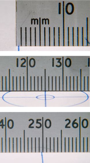
Cal Target – 400 step-mm – merged It’s half a millimeter short on each end!
More on this tomorrow …
The GCMC source code as a GitHub Gist:
This file contains hidden or bidirectional Unicode text that may be interpreted or compiled differently than what appears below. To review, open the file in an editor that reveals hidden Unicode characters. Learn more about bidirectional Unicode characters(epilog begins) (bCNC may regard plot as done before this returns) M2 (epilog ends) This file contains hidden or bidirectional Unicode text that may be interpreted or compiled differently than what appears below. To review, open the file in an editor that reveals hidden Unicode characters. Learn more about bidirectional Unicode characters(prolog begins) G17 (XY plane) G21 (mm) G40 (no cutter comp) G49 (no tool length comp) G80 (no motion mode) G90 (abs distance) G94 (units per minute) (prolog ends) This file contains hidden or bidirectional Unicode text that may be interpreted or compiled differently than what appears below. To review, open the file in an editor that reveals hidden Unicode characters. Learn more about bidirectional Unicode characters// Grid pattern to check XY scaling // Ed Nisley KE4ZNU – 2021-11 // gcmc -P 4 –pedantic –prolog prolog.gcmc –epilog epilog.gcmc –output 'Scale Grid.ngc' 'Scale Grid.gcmc' include("engrave.inc.gcmc"); FALSE = 0; TRUE = !FALSE; //—– // Define useful constants SafeZ = [-,-,10.0mm]; // above all obstructions TravelZ = [-,-,2.0mm]; // within engraving / milling area PenZ = [-,-,-1.0mm]; // depth for good inking PenSpeed = 2000mm; //—– // Overall values PlotSize = [250mm,200mm,-]; comment("PlotSize: ",PlotSize); GridSize = [25mm,25mm,-]; Margins = [5mm,5mm,-]; CenterOD = 5.0mm; TextFont = FONT_HSANS_1_RS; // single stroke stick font TextSize = 3.0 * [1.0mm,1.0mm]; //—– // Draw it feedrate(PenSpeed); comment("Draw title info"); tp = scale(typeset("Scale & Backlash Test Pattern",TextFont),TextSize); tp += [-PlotSize.x/2 + GridSize.x/2,PlotSize.y/2 – GridSize.y/2,-]; engrave(tp,TravelZ.z,PenZ.z); tp = scale(typeset("Grid " + GridSize,TextFont),TextSize); tp += [-PlotSize.x/2 + GridSize.x/2,PlotSize.y/2 – GridSize.y/2 – 1.5*TextSize.y,-]; engrave(tp,TravelZ.z,PenZ.z); tp = scale(typeset("F " + PenSpeed + "/min",TextFont),TextSize); tp += [-PlotSize.x/2 + GridSize.x/2,PlotSize.y/2 – GridSize.y/2 – 3.0*TextSize.y,-]; engrave(tp,TravelZ.z,PenZ.z); tp = scale(typeset("Ed Nisley – KE4ZNU",TextFont),TextSize); tp += [-PlotSize.x/2 + GridSize.x/2,-(PlotSize.y/2 – GridSize.y/2),-]; engrave(tp,TravelZ.z,PenZ.z); tp = scale(typeset("softsolder.com",TextFont),TextSize); tp += [-PlotSize.x/2 + GridSize.x/2,-(PlotSize.y/2 – GridSize.y/2 + 1.5*TextSize.y),-]; engrave(tp,TravelZ.z,PenZ.z); comment("Mark center point"); goto(SafeZ); goto([CenterOD/2,0,-]); move(PenZ); circle_cw([0,0]); comment("Label axes"); tp = scale(typeset("X+",TextFont),TextSize); tp += [GridSize.x + 0.5*TextSize.x,-TextSize.y/2,-]; engrave(tp,TravelZ.z,PenZ.z); tp = scale(typeset("Y+",TextFont),TextSize); tp += [-TextSize.x/2,GridSize.y + 0.5*TextSize.y,-]; engrave(tp,TravelZ.z,PenZ.z); comment("Draw left-to-right"); tp = scale(typeset("L to R →",TextFont),TextSize); tp += [-PlotSize.x/2 + GridSize.x/2 – tp[-1].x/2,GridSize.y/2,-]; engrave(tp,TravelZ.z,PenZ.z); goto([-(PlotSize.x/2 + Margins.x),GridSize.y,-]); for (p=[-PlotSize.x/2,GridSize.y,-] ; p.x <= PlotSize.x/2 ; p.x += GridSize.x ) { comment(" p: ",p); goto(p); move(PenZ); move_r([-,-GridSize.y,-]); goto(TravelZ); } comment("Draw right-to-left"); tp = scale(typeset("R to L ←",TextFont),TextSize); tp += [PlotSize.x/2 – GridSize.x/2 – tp[-1].x/2,-GridSize.y/2,-]; engrave(tp,TravelZ.z,PenZ.z); goto([(PlotSize.x/2 + Margins.x),-GridSize.y,-]); for (p=[PlotSize.x/2,-GridSize.y,-] ; p.x >= -PlotSize.x/2 ; p.x -= GridSize.x ) { comment(" p: ",p); goto(p); move(PenZ); move_r([-,GridSize.y,-]); goto(TravelZ); } comment("Draw bottom-to-top"); tp = scale(typeset("B to T ↑",TextFont),TextSize); tp += [-GridSize.x/2 – tp[-1].x/2,-(PlotSize.y/2 – TextSize.y),-]; engrave(tp,TravelZ.z,PenZ.z); goto([-GridSize.x,-(PlotSize.y/2 + Margins.y),-]); for (p=[-GridSize.x,-PlotSize.y/2,-] ; p.y <= PlotSize.y/2 ; p.y += GridSize.y ) { comment(" p: ",p); goto(p); move(PenZ); move_r([GridSize.x,-,-]); goto(TravelZ); } comment("Draw top-to-bottom"); tp = scale(typeset("T to B ↓",TextFont),TextSize); tp += [GridSize.x/2 – tp[-1].x/2,(PlotSize.y/2 – 1.5*TextSize.y),-]; engrave(tp,TravelZ.z,PenZ.z); goto([GridSize.x,(PlotSize.y/2 + Margins.y),-]); for (p=[GridSize.x,PlotSize.y/2,-] ; p.y >= -PlotSize.y/2 ; p.y -= GridSize.y ) { comment(" p: ",p); goto(p); move(PenZ); move_r([-GridSize.x,-,-]); goto(TravelZ); } comment("Draw circles"); maxr = (PlotSize.x < PlotSize.y) ? PlotSize.x/2 : PlotSize.y/2; for (r=GridSize.x/2 ; r <= maxr ; r += GridSize.x) { comment(" r: ",r); goto([-r,0,-]); move(PenZ); circle_cw([0,0,-]); goto(TravelZ); } goto(SafeZ); goto([0,0,-]);
-
Subscribe
Subscribed
Already have a WordPress.com account? Log in now.
 The Smell of Molten Projects in the Morning