The least horrible way to get events from the keypad turned out to be a simple non-blocking poll from Python’s select library, then sucking the event input queue dry; the main loop now does what might be grandiosely overstated as cooperative multitasking. Well, hey, it reads lines from mplayer’s output pipe and processes keypad events and doesn’t stall (for very long) and that’s multi enough for me.
It extracts the stream title from the ICY Info line, but I still haven’t bothered with a display. It may well turn out that this thing doesn’t need a display. The stream title will be enclosed in single quotes, but it may also contain non-escaped and non-paired single quotes (a.k.a. apostrophes): the obvious parsing strategy doesn’t work. I expect titles can contain non-escaped semicolons, too, which will kill the algorithm I’m using stone cold dead. Some try - except armor may be appropriate.
This code does not tolerate a crappy WiFi connection very well at all. I eventually replaced a long-antenna WiFi adapter with an actual Ethernet cable and all the mysterious problems at the far end of the house Went Away. Soooo this code won’t tolerate random network stream dropouts very well, either; we’ll see how poorly that plays out in practice.
The hackery to monitor / kill / restart / clean up after mplayer and its pipes come directly from seeing what failed, then whacking that mole in the least intrusive manner possible. While it would be better to wrap a nice abstract model around what mplayer is (assumed to be) doing, it’s not at all clear to me that I can build a sufficiently durable model to be worth the effort. Basically, trying to automate a program designed to be human-interactive is always a recipe for disaster.
The option for the Backspace / Del key lets you do remote debugging by editing the code to just bail out of the loop instead of shut down. Unedited, it’s a power switch: the Pi turns off all the peripherals and shuts itself down. The key_hold conditional means you must press-and-hold that button to kill the power, but don’t run this on your desktop PC, OK?
Autostarting the program requires one line in /etc/rc.local:
sudo -u pi python /home/pi/Streamer.py &
AFAICT, using cron with an @REBOOT line has timing issues with the network being available, but I can’t point to any solid evidence that hacking rc.local waits until the network is up, either. So far, so good.
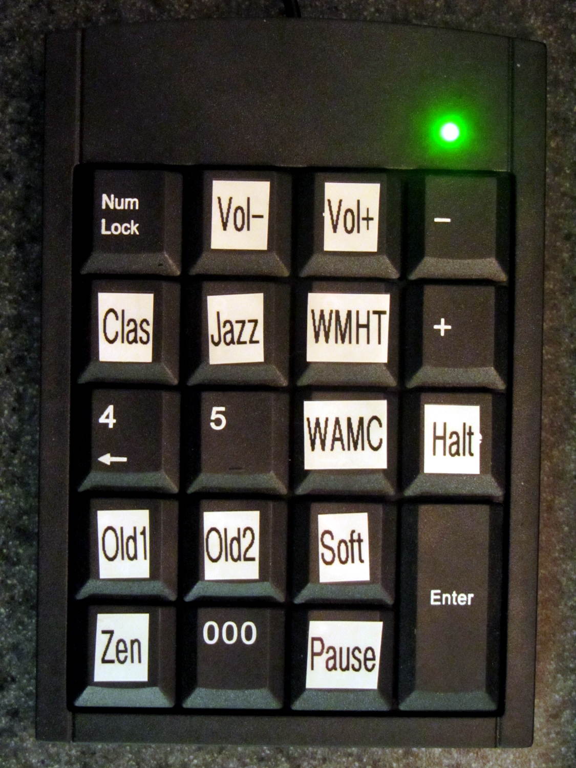
I make no apologies for any of the streams; I needed streams behind all the buttons and picked stuff from Xiph’s listing. The AAC+ streams from the Public Domain Project give mplayer a bad bellyache; I think its codecs can’t handle the “+” part of AAC+.
All in all, not bad for a bit over a hundred lines of code, methinks…
More fiddling will happen, but we need some continuous experience for that; let the music roll!
The Python program as a GitHub Gist:
| from evdev import InputDevice,ecodes,KeyEvent | |
| import subprocess32 | |
| import select | |
| import re | |
| import sys | |
| Media = {'KEY_KP7' : ['Classical',['mplayer','-playlist','http://stream2137.init7.net/listen.pls'%5D%5D, | |
| 'KEY_KP8' : ['Jazz',['mplayer','-playlist','http://stream2138.init7.net/listen.pls'%5D%5D, | |
| 'KEY_KP9' : ['WMHT',['mplayer','http://live.str3am.com:2070/wmht1'%5D%5D, | |
| 'KEY_KP4' : ['Dub 1',['mplayer','-playlist','http://dir.xiph.org/listen/2645/listen.m3u'%5D%5D, | |
| 'KEY_KP5' : ['Dub 2',['mplayer','http://streaming207.radionomy.com:80/MiamiClubMusiccom'%5D%5D, | |
| 'KEY_KP6' : ['WAMC',['mplayer','http://pubint.ic.llnwd.net/stream/pubint_wamc'%5D%5D, | |
| 'KEY_KP1' : ['Oldies 1',['mplayer','http://streaming304.radionomy.com:80/keepfree60s'%5D%5D, | |
| 'KEY_KP2' : ['Oldies 2',['mplayer','http://streaming207.radionomy.com:80/1000Oldies'%5D%5D, | |
| 'KEY_KP3' : ['Soft Rock',['mplayer','http://streaming201.radionomy.com:80/SoftRockRadio'%5D%5D, | |
| 'KEY_KP0' : ['Smooth',['mplayer','http://streaming202.radionomy.com:80/The-Smooth-Lounge'%5D%5D | |
| } | |
| CurrentKC = 'KEY_KP7' | |
| Controls = {'KEY_KPSLASH' : '/', | |
| 'KEY_KPASTERISK' : '*', | |
| 'KEY_KPENTER' : ' ', | |
| 'KEY_KPMINUS' : '<', | |
| 'KEY_KPPLUS' : '>' | |
| } | |
| # set up event input and polling | |
| k=InputDevice('/dev/input/keypad') | |
| kp = select.poll() | |
| kp.register(k.fileno(),select.POLLIN + select.POLLPRI + select.POLLERR) | |
| # set up files for mplayer pipes | |
| lw = open('/tmp/mp.log','w') # mplayer piped output | |
| lr = open('/tmp/mp.log','r') # … reading that output | |
| # Start the default stream | |
| print 'Starting mplayer on',Media[CurrentKC][0]," -> ",Media[CurrentKC][-1][-1] | |
| p = subprocess32.Popen(Media[CurrentKC][-1],stdin=subprocess32.PIPE,stdout=lw,stderr=subprocess32.STDOUT) | |
| print ' … running' | |
| #— Play the streams | |
| while True: | |
| # pluck next line from mplayer and decode it | |
| text = lr.readline() | |
| if 'ICY Info: ' in text: | |
| trkinfo = text.split(';') | |
| for ln in trkinfo: | |
| if 'StreamTitle' in ln: | |
| trkhit = re.search(r"StreamTitle='(.*)'",ln) | |
| TrackName = trkhit.group(1) | |
| print 'Track name: ', TrackName | |
| break | |
| elif 'Exiting…' in text: | |
| print 'Got EOF / stream cutoff' | |
| print ' … killing dead mplayer' | |
| p.kill() | |
| print ' … flushing pipes' | |
| lw.truncate(0) | |
| print ' … discarding keys' | |
| while [] != kp.poll(0): | |
| kev = k.read | |
| print ' … restarting mplayer: ',Media[CurrentKC][0] | |
| p = subprocess32.Popen(Media[CurrentKC][-1],stdin=subprocess32.PIPE,stdout=lw,stderr=subprocess32.STDOUT) | |
| print ' … running' | |
| continue | |
| # accept pending events from keypad | |
| if [] != kp.poll(0): | |
| kev = k.read() | |
| for e in kev: | |
| if e.type == ecodes.EV_KEY: | |
| kc = KeyEvent(e).keycode | |
| if kc == 'KEY_NUMLOCK': | |
| continue | |
| # print 'Got: ',kc | |
| if (kc == 'KEY_BACKSPACE') and (KeyEvent(e).keystate == KeyEvent.key_hold): | |
| if True: | |
| print 'Backspace = shutdown!' | |
| p = subprocess32.call(['sudo','shutdown','-HP',"now"]) | |
| else: | |
| print 'BS = bail from main, ssh to restart!' | |
| sys.exit(0) | |
| if KeyEvent(e).keystate != KeyEvent.key_down: | |
| continue | |
| if kc in Controls: | |
| print 'Control:', kc | |
| try: | |
| p.stdin.write(Controls[kc]) | |
| except Exception as e: | |
| print "Can't send control: ",e | |
| print ' … restarting player: ',Media[CurrentKC][0] | |
| p = subprocess32.Popen(Media[CurrentKC][-1],stdin=subprocess32.PIPE,stdout=lw,stderr=subprocess32.STDOUT) | |
| print ' … running' | |
| if kc in Media: | |
| print 'Switching stream to ',Media[kc][0]," -> ",Media[kc][-1][-1] | |
| CurrentKC = kc | |
| print ' … halting player' | |
| try: | |
| p.communicate(input='q') | |
| except Exception as e: | |
| print 'Perhaps mplayer died?',e | |
| print ' … killing it for sure' | |
| p.kill() | |
| print ' … flushing pipes' | |
| lw.truncate(0) | |
| print ' … restarting player: ',Media[CurrentKC][0] | |
| p = subprocess32.Popen(Media[CurrentKC][-1],stdin=subprocess32.PIPE,stdout=lw,stderr=subprocess32.STDOUT) | |
| print ' … running' | |
| print 'Out of loop!' |