Having spent a bit of effort wringing enough precision from an Arduino to make the 60 kHz quartz resonator tester, this came as a relief:
DDS frequency: 180000000.0000000 Hz
epsilon: 0.0000001 Hz
step: 0.0419095 Hz
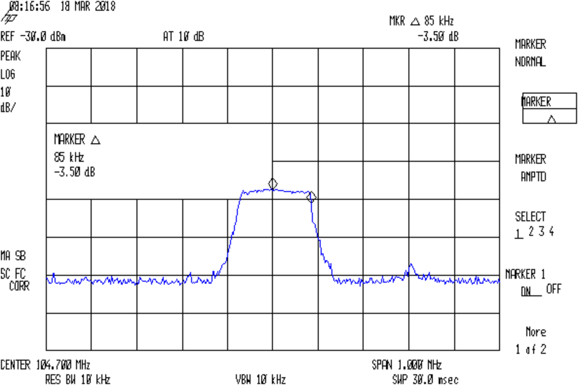
Center frequency: 146520000.0000000 Hz
146520000.0000001 Hz
146520000.0000002 Hz
146520000.0000003 Hz
146520000.0000004 Hz
146520000.0000004 Hz
146520000.0000005 Hz
146520000.0000006 Hz
146520000.0000007 Hz
146520000.0000008 Hz
146520000.0000009 Hz
146520000.0000010 Hz
... snippage ...
146520000.0000099 Hz
146520000.0000100 Hz
146520000.0419195 Hz
146520000.0838290 Hz
146520000.1257386 Hz
146520000.1676481 Hz
146520000.2095576 Hz
146520000.2514671 Hz
146520000.2933766 Hz
146520000.3352861 Hz
146520000.3771957 Hz
146520000.4191052 Hz
146520000.4610147 Hz
146520000.5029242 Hz
146520000.5448337 Hz
146520000.5867432 Hz
146520000.6286528 Hz
146520000.6705623 Hz
146520000.7124718 Hz
146520000.7543813 Hz
146520000.7962908 Hz
146520000.8382003 Hz
146520000.8801098 Hz
146520000.9220194 Hz
146520000.9639289 Hz
146520001.0058384 Hz
146520001.0477479 Hz
146520001.0896574 Hz
146520001.1315669 Hz
146520001.1734765 Hz
Which comes from a PJRC Teensy 3.6 running this code:
double DDSFreq, EpsilonFreq, DDSStepFreq;
double CenterFreq, TestFreq;

... in setup() ...

  DDSFreq = 180.0e6;
  EpsilonFreq = 1.0e-7;
  DDSStepFreq = DDSFreq / (1LL << 32);
  Serial.printf("DDS frequency: %18.7f Hz\n",DDSFreq);
  Serial.printf("      epsilon: %18.7f Hz\n",EpsilonFreq);
  Serial.printf("         step: %18.7f Hz\n\n",DDSStepFreq);

  CenterFreq = 146520000.0;
  TestFreq = CenterFreq;
  Serial.printf("Center frequency: %18.7f Hz\n",CenterFreq);

... in loop() ...

  if (TestFreq < (CenterFreq + 100*EpsilonFreq))
    TestFreq += EpsilonFreq;
  else
    TestFreq += DDSStepFreq;

  Serial.printf(" %18.7f Hz\n",TestFreq);
The IEEE-754 spec says a double floating-point variable carries about 15.9 decimal digits, which agrees with the 9 integer + 7 fraction digits. The highlight lowlight (gray bar) in the first figure shows the slight stumble where adding 1e-7 changes the sum, but not quite enough to affect the displayed fraction.
In round numbers, an increment of 1e-5 would work just fine:
  146520000.0000100 Hz
  146520000.0000200 Hz
  146520000.0000300 Hz
  146520000.0000401 Hz
  146520000.0000501 Hz
  146520000.0000601 Hz
  146520000.0000701 Hz
  146520000.0000801 Hz
  146520000.0000901 Hz
  146520000.0001001 Hz
  146520000.0001101 Hz
  146520000.0001202 Hz
  146520000.0001302 Hz
  146520000.0001402 Hz
  146520000.0001502 Hz
  146520000.0001602 Hz
  146520000.0001702 Hz
  146520000.0001802 Hz
  146520000.0001903 Hz
  146520000.0002003 Hz
  146520000.0002103 Hz
  146520000.0002203 Hz
  146520000.0002303 Hz
You’d use the “smallest of all” epsilon in a multiplied increment, perhaps to tick a value based on a knob or some such. Fine-tuning a VHF frequency with millihertz steps probably doesn’t make much practical sense.
The DDS frequency increment works out to 41.9095 mHz, slightly larger than with the Arduino, because it’s fot a cheap DDS eBay module with an AD9851 running a 180 MHz (6 × 30 MHz ) clock.