Ed Nisley's Blog: Shop notes, electronics, firmware, machinery, 3D printing, laser cuttery, and curiosities. Contents: 100% human thinking, 0% AI slop.
Category: Software
General-purpose computers doing something specific
I want to stress-test some LEDs for the long-stalled bike taillight project with a high current / low duty cycle drive. The usual specs give something like 100 mA at 10% duty cycle in a 100 μs period, but maybe they’ll withstand more abuse than that; I don’t have any specs whatsoever for these LEDs. The usual DC rating is 20 mA, so 100 mA at 20%, say 2 ms in a 10 ms period, should give the same average power as the DC spec. I plan to run them continuously until some failures to pop up or it’s obvious they’re doing just fine.
Although this would be a dandy Arduino project, a classic 555 timer IC makes more sense for something that must run continuously without changing anything. The usual 555 circuit restricts the duty cycle to more than 50% for high-active pulses, a bit over the 20% this task calls for. The simplest workaround is a Schottky diode across the discharge resistor to separate the two current paths: charge uses the upper resistor, discharge the lower, with the diode forward drop thrown in to complicate the calculations.
Rather than putz around with calculation, a few minutes iterating with Linear Technologies’ LTSpice IV produces a reasonable result:
NE555 pulse generator
In round numbers, a 1 μF timing capacitor, 2.7 kΩ charge resistor, and 13 kΩ discharge resistor do the trick. Given the usual capacitor tolerances, each resistor should include a twiddlepot of about half the nominal value: 1 kΩ and 5 kΩ, respectively.
I’m thinking of repurposing those Wouxun KG-UV3D batteries for this task and found a 7.5 V 3.5 A wall wart in the heap that will be close enough for the test rig. The 555 output should drive a logic-level MOSFET just fine, although even an ordinary FET would probably be OK for the relatively low current required for LED toasting.
A small buzzer motor should come in handy for something. Perhaps alerting you to the presence of AC magnetic fields? Anyhow, driving a pager motor from one of the spare bits on the DL1414 display control shift register worked out well enough:
Motor Driver with LED Character Display
These cute little surplus motors expect a 2.5 V supply and buzz overenthusiastically at 5 V; the 100 Ω resistor reduces the current to about 30 mA. That says the motor now runs on about 2 V and I admit picking the resistor became totally empirical, because starting even a little teeny motor requires more current than keeping it running and my first guess was far too high. The 1N4148 diode can handle a few tens of milliamps and will become inadequate for larger motors.
The MOSFET driver resides between the LED displays, with the motor hanging in mid-air on a long wire and the diode hiding behind the motor terminals:
Buzzer Motor Driver – breadboard
Dropping the motor control bit into the DL1414 struct suggested that renaming the whole affair would be a Good Idea:
union CONTROLBITS_ {
	word ShiftWord;				// word overlay
	struct {					// bitfield sent to the display
		unsigned int Addr:2;
		unsigned int NotWrite:1;
		unsigned int Ctl3_6:4;			// unused bits
		unsigned int Motor:1;			// buzzer motor drive
		unsigned int Data:7;
		unsigned int Data7:1;			// unused bit
	} ShiftBits;
};
Controlling the motor requires changing only that single bit in the shift register:
We assume that the DL1414 control bits remain properly configured from the previous operation. The variable holding that struct (actually, the union wrapped around it), must have global scope so everybody uses the most recent bits. Global variables are obviously fraught with peril; hide it inside a method or other fancy construct, as you prefer.
The demo code alternates the motor between on and off as you press Button 1 and shows the current status on the DL1414 display. I mashed up the button demo code with the LED character code, then sprinkled the motor on top:
The picture shows the motor sitting idle and the DL1414 reporting OFF.
When you turn the knob, that display shows the value of the knob click counter, with the first character indicating the motor state.
If you ran the motor directly from an Arduino PWM output, you might get some speed control, but I think the dynamic range wouldn’t justify the effort. Buzzing in patterns of a few hundred milliseconds over the course of a second might be more distinctive; you could even do Morse code.
The Arduino source code:
// Quadrature knob with switch
// Ed Nisley - KE4ANU - November 2012
// Based on:
// https://softsolder.com/2009/03/03/reading-a-quadrature-encoded-knob-in-double-quick-time/
//----------
// Pin assignments
const byte PIN_KNOB_A = 2; // knob A switch - must be on ext interrupt 2
const byte PIN_KNOB_B = 4; // .. B switch
const byte PIN_BUTTONS = A5; // .. push-close momentary switch
const byte PIN_MOSI = 8; // data to shift reg
const byte PIN_SCK = 6; // shift clock to shift reg
const byte PIN_RCKB = 7; // latch clock for LED Bargraph
const byte PIN_RCKC = 12; // latch clock for LED character display
const byte PIN_SYNC = 13; // scope sync
//----------
// Constants
const int UPDATEMS = 10; // update LEDs only this many ms apart
#define TCCRxB 0x02 // Timer prescaler
enum KNOB_STATES {KNOB_CLICK_0,KNOB_CLICK_1};
enum BUTTONS {SW_KNOB, B_1, B_2, B_3, B_4, N_BUTTONS};
#define LED_SIZE 4 // chars per LED
#define LED_DISPLAYS 1 // number of displays
#define LED_CHARS (LED_DISPLAYS * LED_SIZE)
union CONTROLBITS_ {
word ShiftWord; // word overlay
struct { // bitfield sent to the display
unsigned int Addr:2;
unsigned int NotWrite:1;
unsigned int Ctl3_6:4; // unused bits
unsigned int Motor:1; // buzzer motor drive
unsigned int Data:7;
unsigned int Data7:1; // unused bit
} ShiftBits;
};
//----------
// Globals
volatile char KnobCounter = 0;
volatile char KnobState;
char PrevKnobCounter = 0;
byte Button, PrevButton;
// ButtonThreshold must have N_BUTTONS elements, last = 1024
word ButtonThreshold[] = {265/2, (475+265)/2, (658+475)/2, (834+658)/2, (1023+834)/2, 1024};
union CONTROLBITS_ ControlBits;
char LEDCharBuffer[LED_CHARS + 1] = "HELO"; // raw char buffer, can be used as a string
unsigned long MillisNow;
unsigned long MillisThen;
//-- Helper routine for printf()
int s_putc(char c, FILE *t) {
Serial.write(c);
}
//-- Pulse selected pin high
void PulsePinHigh(byte PinID) {
digitalWrite(PinID,HIGH);
digitalWrite(PinID,LOW);
}
//-- Write single char to DL1414, other control bits as defined
void WriteLEDChar(char Char,char CharID) {
ControlBits.ShiftBits.Data = Char & 0x7F;
ControlBits.ShiftBits.Addr = ~CharID & 0x03; // reverse order of chars
ControlBits.ShiftBits.NotWrite = 1; // set up data and address
shiftOut(PIN_MOSI,PIN_SCK,MSBFIRST,ControlBits.ShiftWord >> 8);
shiftOut(PIN_MOSI,PIN_SCK,MSBFIRST,ControlBits.ShiftWord & 0x00ff);
PulsePinHigh(PIN_RCKC);
// delay(1000);
ControlBits.ShiftBits.NotWrite = 0; // write the character
shiftOut(PIN_MOSI,PIN_SCK,MSBFIRST,ControlBits.ShiftWord >> 8);
shiftOut(PIN_MOSI,PIN_SCK,MSBFIRST,ControlBits.ShiftWord & 0x00ff);
PulsePinHigh(PIN_RCKC);
// delay(1000);
ControlBits.ShiftBits.NotWrite = 1; // disable write
shiftOut(PIN_MOSI,PIN_SCK,MSBFIRST,ControlBits.ShiftWord >> 8);
shiftOut(PIN_MOSI,PIN_SCK,MSBFIRST,ControlBits.ShiftWord & 0x00ff);
PulsePinHigh(PIN_RCKC);
// delay(1000);
}
void WriteLEDString(char *pString) {
for (byte i=0; (i < LED_CHARS) && *pString; ++i)
WriteLEDChar(*pString++,i);
return;
}
void MotorControl(byte State) {

	ControlBits.ShiftBits.Motor = State ? 1 : 0;

	shiftOut(PIN_MOSI,PIN_SCK,MSBFIRST,ControlBits.ShiftWord >> 8);
	shiftOut(PIN_MOSI,PIN_SCK,MSBFIRST,ControlBits.ShiftWord & 0x00ff);
	PulsePinHigh(PIN_RCKC);

}
//-- Knob interrupt handler
void KnobHandler(void)
{
byte Inputs;
Inputs = digitalRead(PIN_KNOB_B) << 1 | digitalRead(PIN_KNOB_A); // align raw inputs
// Inputs ^= 0x02; // fix direction
switch (KnobState << 2 | Inputs) {
case 0x00 : // 0 00 - glitch
break;
case 0x01 : // 0 01 - UP to 1
KnobCounter++;
KnobState = KNOB_CLICK_1;
break;
case 0x03 : // 0 11 - DOWN to 1
KnobCounter--;
KnobState = KNOB_CLICK_1;
break;
case 0x02 : // 0 10 - glitch
break;
case 0x04 : // 1 00 - DOWN to 0
KnobCounter--;
KnobState = KNOB_CLICK_0;
break;
case 0x05 : // 1 01 - glitch
break;
case 0x07 : // 1 11 - glitch
break;
case 0x06 : // 1 10 - UP to 0
KnobCounter++;
KnobState = KNOB_CLICK_0;
break;
default : // something is broken!
KnobCounter = 0;
KnobState = KNOB_CLICK_0;
}
}
//-- Read and decipher analog switch inputs
// returns N_BUTTONS if no buttons pressed
byte ReadButtons(int PinNumber) {
word RawButton;
byte ButtonNum;
RawButton = analogRead(PinNumber);
// printf("RawButton: %d ",RawButton);
for (ButtonNum = 0; ButtonNum <= N_BUTTONS; ButtonNum++){
// printf(" (%d:%d)",ButtonNum,ButtonThreshold[ButtonNum]);
if (RawButton < ButtonThreshold[ButtonNum])
break;
}
// printf(" ButtonNum %d\n",ButtonNum);
return ButtonNum;
}
//------------------
// Set things up
void setup() {
pinMode(PIN_SYNC,OUTPUT);
digitalWrite(PIN_SYNC,LOW); // show we arrived
// TCCR1B = TCCRxB; // set frequency for PWM 9 & 10
// TCCR2B = TCCRxB; // set frequency for PWM 3 & 11
pinMode(PIN_KNOB_B,INPUT_PULLUP);
pinMode(PIN_KNOB_A,INPUT_PULLUP);
pinMode(PIN_MOSI,OUTPUT);
digitalWrite(PIN_MOSI,LOW);
pinMode(PIN_SCK,OUTPUT);
digitalWrite(PIN_SCK,LOW);
pinMode(PIN_RCKB,OUTPUT);
digitalWrite(PIN_RCKB,LOW);
pinMode(PIN_RCKC,OUTPUT);
digitalWrite(PIN_RCKB,LOW);
KnobState = digitalRead(PIN_KNOB_A);
Button = PrevButton = ReadButtons(PIN_BUTTONS);
attachInterrupt((PIN_KNOB_A - 2),KnobHandler,CHANGE);
Serial.begin(9600);
fdevopen(&s_putc,0); // set up serial output for printf()
printf("Motor, knob, and buttons\r\nEd Nisley - KE4ZNU - December 2012\r\n");
ControlBits.ShiftWord = 0x0000;
WriteLEDString(LEDCharBuffer);
delay(1000);
MillisThen = millis();
}
//------------------
// Run the test loop
void loop() {
MillisNow = millis();
if ((MillisNow - MillisThen) > UPDATEMS) {
digitalWrite(PIN_SYNC,HIGH);
Button = ReadButtons(PIN_BUTTONS);
if (PrevButton != Button) {
if (Button == N_BUTTONS) {
printf("Button %d released\n",PrevButton);
}
else {
printf("Button %d pressed\n",Button);
if (Button == B_1) {
ControlBits.ShiftBits.Motor = ~ControlBits.ShiftBits.Motor;
sprintf(LEDCharBuffer,"%s",
ControlBits.ShiftBits.Motor?"ON ":"OFF ");
WriteLEDString(LEDCharBuffer);
}
}
PrevButton = Button;
}
if (PrevKnobCounter != KnobCounter) {
printf("Knob count: %d\n",KnobCounter);
sprintf(LEDCharBuffer,"%c%3d",
ControlBits.ShiftBits.Motor?'*':'_',
KnobCounter);
WriteLEDString(LEDCharBuffer);
PrevKnobCounter = KnobCounter;
}
digitalWrite(PIN_SYNC,LOW);
MillisThen = MillisNow;
}
}
Reading more than a few pushbuttons requires multiplexing, with a parallel-in shift register similar to the old 74LS166 being popular (and supported by the shiftIn() function). You can also use an Arduino analog input to multiplex the buttons, at the cost of a resistor string that probably draws more current and costs more than a logic IC:
Knob and Buttons
The switches produce voltages at the analog input which are not the evenly spaced 1 V increments you might expect: the 10 kΩ pullup appears in parallel with the sum of all the resistors above the closed switch, so the voltages come out a bit higher. The notation to the right of each switch indicates the voltage and equivalent ADC value, assuming a 5.0 V AVREF that won’t be quite right for your circuit. The analog input spec recommends less than 10 kΩ source resistance, but you could probably go much higher without any problem; the ADC output value need not be particularly accurate.
If you happen to have a SIP resistor pack containing five separate resistors (not the usual nine resistors in a 10 lead SIP), then the circuitry doesn’t amount to much:
Knob and Buttons – breadboard
It’s sitting in front of the ZNVL110A MOSFETs driving the RGB LED strip light. Those flat blue surplus buttons came in pairs pre-configured with wire leads and just begged to get out of the heap for this occasion. The encoder knob remains as before, with its shaft push-on momentary switch still going directly to analog input A5. The new button circuitry connects to that switch lead, ungainly though it may appear, with the gray wire bringing VCC from the cluster of sensorinputs.
To simplify reading the buttons, build an array of threshold voltages about halfway between the calculated switch voltages:
You could do the circuit calculation and VCC calibration in there, too, but those widely spaced increments don’t pose much of a problem. The table must include an end marker of 1024, greater than any possible analog input.
Then you read the button input voltage and walk upward through the table until the value falls below a threshold, a process I find much cleaner and easier than a pile of conditionals sprinkled with fiddly constants.
byte ReadButtons(byte PinNumber) {

word RawButton;
byte ButtonNum;

	RawButton = analogRead(PinNumber);

	for (ButtonNum = 0; ButtonNum <= N_BUTTONS; ButtonNum++){
		if (RawButton < ButtonThreshold[ButtonNum])
			break;
	}

	return ButtonNum;
}
As long as the button stays down, that function returns its ID number. You can detect both edges of a button press:
Ed Nisley - KE4ZNU - December 2012
Knob encoder and buttons
Ed Nisley - KE4ZNU - December 2012
Knob count: 2
Knob count: 3
Knob count: 4
Knob count: 3
Knob count: 2
Knob count: 1
Knob count: 0
Knob count: 2
Knob count: 4
Knob count: 5
Knob count: 6
Knob count: 7
Knob count: 8
Knob count: 11
Knob count: 15
Knob count: 16
Knob count: 17
Button 0 pressed
Button 0 released
Button 1 pressed
Button 1 released
Button 2 pressed
Button 2 released
Button 3 pressed
Button 3 released
Button 4 pressed
Button 4 released
Button 2 pressed
Button 2 released
This scheme works for a single button pressed at a time, which is generally how you use discrete buttons. It’s not appropriate for keyboards or multi-axis joystick button arrays, which you could multiplex using resistors that produce accurate binary steps, but that’s fraught with peril and error.
As with all non-interrupt-driven buttons, you must poll the button input at a reasonable rate to have a responsive UI. Non-blocking loop() code will be your friend.
It made sense to exercise the new buttons in the encoder knob demo code, so this will look familiar…
The Arduino source code:
// Quadrature knob with switch
// Ed Nisley - KE4ANU - November 2012
// Based on:
// https://softsolder.com/2009/03/03/reading-a-quadrature-encoded-knob-in-double-quick-time/
//----------
// Pin assignments
const byte PIN_KNOB_A = 2; // knob A switch - must be on ext interrupt 2
const byte PIN_KNOB_B = 4; // .. B switch
const byte PIN_BUTTONS = A5; // .. push-close momentary switch
const byte PIN_SYNC = 13; // scope sync
//----------
// Constants
const int UPDATEMS = 10; // update LEDs only this many ms apart
#define TCCRxB 0x02 // Timer prescaler
enum KNOB_STATES {KNOB_CLICK_0,KNOB_CLICK_1};
enum BUTTONS {SW_KNOB, B_1, B_2, B_3, B_4, N_BUTTONS};
//----------
// Globals
volatile char KnobCounter = 0;
volatile char KnobState;
char PrevKnobCounter = 0;
byte Button, PrevButton;
// ButtonThreshold must have N_BUTTONS elements, last = 1024
word ButtonThreshold[] = {265/2, (475+265)/2, (658+475)/2, (834+658)/2, (1023+834)/2, 1024};
unsigned long MillisNow;
unsigned long MillisThen;
//-- Helper routine for printf()
int s_putc(char c, FILE *t) {
Serial.write(c);
}
//-- Knob interrupt handler
void KnobHandler(void)
{
byte Inputs;
Inputs = digitalRead(PIN_KNOB_B) << 1 | digitalRead(PIN_KNOB_A); // align raw inputs
// Inputs ^= 0x02; // fix direction
switch (KnobState << 2 | Inputs) {
case 0x00 : // 0 00 - glitch
break;
case 0x01 : // 0 01 - UP to 1
KnobCounter++;
KnobState = KNOB_CLICK_1;
break;
case 0x03 : // 0 11 - DOWN to 1
KnobCounter--;
KnobState = KNOB_CLICK_1;
break;
case 0x02 : // 0 10 - glitch
break;
case 0x04 : // 1 00 - DOWN to 0
KnobCounter--;
KnobState = KNOB_CLICK_0;
break;
case 0x05 : // 1 01 - glitch
break;
case 0x07 : // 1 11 - glitch
break;
case 0x06 : // 1 10 - UP to 0
KnobCounter++;
KnobState = KNOB_CLICK_0;
break;
default : // something is broken!
KnobCounter = 0;
KnobState = KNOB_CLICK_0;
}
}
//-- Read and decipher analog switch inputs
// returns N_BUTTONS if no buttons pressed
byte ReadButtons(int PinNumber) {
word RawButton;
byte ButtonNum;
RawButton = analogRead(PinNumber);
// printf("RawButton: %d ",RawButton);
for (ButtonNum = 0; ButtonNum <= N_BUTTONS; ButtonNum++){
// printf(" (%d:%d)",ButtonNum,ButtonThreshold[ButtonNum]);
if (RawButton < ButtonThreshold[ButtonNum])
break;
}
// printf(" ButtonNum %d\n",ButtonNum);
return ButtonNum;
}
//------------------
// Set things up
void setup() {
pinMode(PIN_SYNC,OUTPUT);
digitalWrite(PIN_SYNC,LOW); // show we arrived
// TCCR1B = TCCRxB; // set frequency for PWM 9 & 10
// TCCR2B = TCCRxB; // set frequency for PWM 3 & 11
pinMode(PIN_KNOB_B,INPUT_PULLUP);
pinMode(PIN_KNOB_A,INPUT_PULLUP);
KnobState = digitalRead(PIN_KNOB_A);
Button = PrevButton = ReadButtons(PIN_BUTTONS);
attachInterrupt((PIN_KNOB_A - 2),KnobHandler,CHANGE);
Serial.begin(9600);
fdevopen(&s_putc,0); // set up serial output for printf()
printf("Knob encoder and buttons\r\nEd Nisley - KE4ZNU - December 2012\r\n");
MillisThen = millis();
}
//------------------
// Run the test loop
void loop() {
MillisNow = millis();
if ((MillisNow - MillisThen) < UPDATEMS) {
digitalWrite(PIN_SYNC,HIGH);
	Button = ReadButtons(PIN_BUTTONS);
	if (PrevButton != Button) {
		if (Button == N_BUTTONS) {
			printf("Button %d released\n",PrevButton);
		}
		else
			printf("Button %d pressed\n",Button);
		PrevButton = Button;
	}
if (PrevKnobCounter != KnobCounter) {
printf("Knob count: %d\n",KnobCounter);
PrevKnobCounter = KnobCounter;
}
digitalWrite(PIN_SYNC,LOW);
MillisThen = MillisNow;
}
}
The heap disgorged some bare passive IR / pyroelectric elements that, IIRC, came from Electronic Goldmine, described as SDA02-54 dual-element sensors. A bit of rummaging and a glance at Nicera’s Fine Datasheet says that can’t possibly be true: the SDA02-54 has a square window. The nearby SSAC10-11, however, has a round window and looks like a better match. Incidentally, that means the Fresnel IR lenses on the Electronic Goldmine site probably won’t work as intended, because the lenses typically produce multiple beams intended to focus on dual (or quad) elements. I suppose you could convert one Fresnel pattern into an IR telescope…
For my present purpose, however, a bare single-element pyroelectric detector will work just fine: the general idea is to detect things out there in front, not make decisions about what’s going on.
Under normal circumstances, where you want decisions, you’d use a module (from, say, Sparkfun) with a passive IR sensor in front of some circuitry that conditions the output and produces yes-no detections. LadyAda has a good description of the workings thereof & interfacings thereto, including a link to the BISS0001 analog chip that does most of the heavy lifting in low-end PIR modules.
What’s the fun in that?
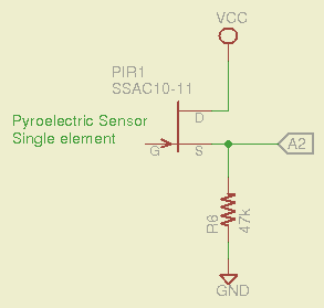
A pyroelectric detector is basically a high-impedance element buffered by a JFET, with its drain and source terminals brought out. IR radiation produces a bias change on the gate, which connects to the (grounded) case through a very very very large-value resistor. That means we can build what amounts to a source follower around the JFET (with all the PIR stuff to the left of the gate not shown):
Passive IR Sensor
The output runs around half a volt, which is a bit low. If you were serious, you’d pass it through an op-amp to boost it by a factor of four or five to around 2.5 V, which would have the additional benefit of lowering the impedance to work better with the Arduino’s ADC input circuitry. For now, I’ll pipe the voltage directly to an Arduino analog input:
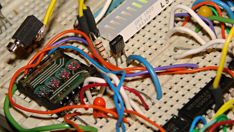
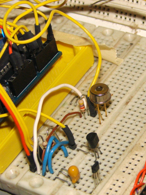
SSAC10-11 PIR Sensor – breadboard
The linear Hall effect magnetic sensor and LM335 temperature sensor live just this side of the PIR can, sharing their VCC and ground connections in a most intimate manner. Remember, this is a breadboard, not a finished circuit… [grin]
The SSAC10-11 (if, indeed, that’s what it is) reports the voltage difference between a reference element shielded within the can and an active element exposed to incoming IR. The DC bias for that lashup produces 650 mV on the 47 kΩ source resistor (about 14 μA) and the internal arrangement produces a lower voltage (and thus current) when the exposed element sees a warmer object, which isn’t quite what I expected. Warming the can by direct finger contact produces an increasing voltage, due to heating the reference element and leaving the sensing element (relatively) cool, at least until conduction equalizes the elements.
I threw in a bit of averaging for each reading, not that it really matters:
#define PAVG 3

word ReadPIR(byte Pin) {
word Sense;

	Sense = analogRead(Pin);
	for (byte i = 1; i < PAVG; i++)
		Sense += analogRead(Pin);

	return Sense / PAVG;
}
The LED bargraph shows the current input as a single bar scaled between the minimum and maximum values, so that the display automatically adjusts to changing conditions. The boolean shift direction sends the bar upward on the breadboard LEDs as the PIR element sees warmer objects, which makes much more sense than showing the actual decreasing sensor voltage. The input generally rests in the green zone and both extremes show nice red bars:
In real life, you’d want a reset button, or some code that gradually drifts the extrema toward the running average of the input, so they’re not stuck forever.
Updating the displays every 100 ms seems about right. It’s crazy sensitive to anything within its field of view; sitting down two feet away is good for a few counts and a palm at 30 cm gives you 15 counts. As expected, the increases and decreases fade away exponentially over the course of a few tens of seconds.
If you wanted to do it right, you’d put a shutter or rotating aperture wheel in front, then track the AC signal difference between “scene” and “reference” views. A tiny Peltier module to stabilize the can temperature would make a lot of sense, too. Or, hey, that LM335 could report the actual can temperature, perhaps with everything embedded in a big thermal mass inside an insulating jacket with a peephole to the outside world. All that’s in the nature of fine tuning…
The Arduino source code:
// Nicera SSAC10-11 Single PIR Sensor
// Ed Nisley - KE4ANU - November 2012
//#include <stdio.h>
//#include <math.h>
//----------
// Pin assignments
const byte PIN_PIR = A2; // Passive IR sensor
const byte PIN_MOSI = 8; // data to shift reg
const byte PIN_SCK = 6; // shift clock to shift reg
const byte PIN_RCKB = 7; // latch clock for LED Bargraph
const byte PIN_RCKC = 12; // latch clock for LED character display
const byte PIN_HEARTBEAT = 13; // DO - Arduino LED
//----------
// Constants
const int UPDATEMS = 100; // update LEDs only this many ms apart
#define TCCRxB 0x02 // Timer prescaler
#define LED_SIZE 4 // chars per LED
#define LED_DISPLAYS 1 // number of displays
#define LED_CHARS (LED_DISPLAYS * LED_SIZE)
union DL1414_ {
word ShiftWord; // word overlay
struct { // bitfield sent to the display
unsigned int Addr:2;
unsigned int NotWrite:1;
unsigned int Ctl3_7:5; // unused bits
unsigned int Data:7;
unsigned int Data7:1; // unused bit
} ShiftBits;
};
//----------
// Globals
int PIRBase, PIRSense, PIRMin, PIRMax, PIRRange, PIRDelta;
int PIRShift;
word LEDBits = 0x5555;
char LEDCharBuffer[LED_CHARS + 1] = "HELO"; // raw char buffer, can be used as a string
unsigned long MillisNow;
unsigned long MillisThen;
//-- Helper routine for printf()
int s_putc(char c, FILE *t) {
Serial.write(c);
}
//-- Send bits to LED bar driver register
void SetBarBits(word Pattern) {
shiftOut(PIN_MOSI,PIN_SCK,MSBFIRST,Pattern >> 8);
shiftOut(PIN_MOSI,PIN_SCK,MSBFIRST,Pattern & 0x00ff);
digitalWrite(PIN_RCKB,HIGH);
digitalWrite(PIN_RCKB,LOW);
}
void PulsePinHigh(byte PinID) {
digitalWrite(PinID,HIGH);
digitalWrite(PinID,LOW);
}
//-- Write single char to DL1414
void WriteLEDChar(char Char,char CharID) {
union DL1414_ DL1414;
DL1414.ShiftBits.Data = Char & 0x7F;
DL1414.ShiftBits.Addr = ~CharID & 0x03; // reverse order of chars
DL1414.ShiftBits.NotWrite = 1; // set up data and address
shiftOut(PIN_MOSI,PIN_SCK,MSBFIRST,DL1414.ShiftWord >> 8);
shiftOut(PIN_MOSI,PIN_SCK,MSBFIRST,DL1414.ShiftWord & 0x00ff);
PulsePinHigh(PIN_RCKC);
// delay(1000);
DL1414.ShiftBits.NotWrite = 0; // write the character
shiftOut(PIN_MOSI,PIN_SCK,MSBFIRST,DL1414.ShiftWord >> 8);
shiftOut(PIN_MOSI,PIN_SCK,MSBFIRST,DL1414.ShiftWord & 0x00ff);
digitalWrite(PIN_RCKC,HIGH);
PulsePinHigh(PIN_RCKC);
// delay(1000);
DL1414.ShiftBits.NotWrite = 1; // disable write
shiftOut(PIN_MOSI,PIN_SCK,MSBFIRST,DL1414.ShiftWord >> 8);
shiftOut(PIN_MOSI,PIN_SCK,MSBFIRST,DL1414.ShiftWord & 0x00ff);
PulsePinHigh(PIN_RCKC);
// delay(1000);
}
void WriteLEDString(char *pString) {
for (byte i=0; (i < LED_CHARS) && *pString; ++i)
WriteLEDChar(*pString++,i);
return;
}
//-- Sample PIR with a dab of averaging
#define PAVG 3
word ReadPIR(byte Pin) {
word Sense;
Sense = analogRead(Pin);
for (byte i = 1; i < PAVG; i++)
Sense += analogRead(Pin);
return Sense / PAVG;
}
//------------------
// Set things up
void setup() {
pinMode(PIN_HEARTBEAT,OUTPUT);
digitalWrite(PIN_HEARTBEAT,LOW); // show we arrived
// TCCR1B = TCCRxB; // set frequency for PWM 9 & 10
// TCCR2B = TCCRxB; // set frequency for PWM 3 & 11
pinMode(PIN_MOSI,OUTPUT);
digitalWrite(PIN_MOSI,LOW);
pinMode(PIN_SCK,OUTPUT);
digitalWrite(PIN_SCK,LOW);
pinMode(PIN_RCKB,OUTPUT);
digitalWrite(PIN_RCKB,LOW);
pinMode(PIN_RCKC,OUTPUT);
digitalWrite(PIN_RCKB,LOW);
Serial.begin(9600);
fdevopen(&s_putc,0); // set up serial output for printf()
printf("Passive IR sensor - SSAC10-11\r\nEd Nisley - KE4ZNU - November 2012\r\n");
WriteLEDString(LEDCharBuffer);
SetBarBits(LEDBits);
PIRBase = ReadPIR(PIN_PIR);
PIRMin = PIRBase - 5;
PIRMax = PIRBase + 5;
PIRRange = PIRMax - PIRMin;
printf("Passive IR base: %d\n",PIRBase);
delay(1000);
MillisThen = millis();
}
//------------------
// Run the test loop
void loop() {
MillisNow = millis();
if ((MillisNow - MillisThen) > UPDATEMS) {
digitalWrite(PIN_HEARTBEAT,HIGH);
PIRSense = ReadPIR(PIN_PIR);
PIRDelta = PIRSense - PIRMin;
PIRMin = min(PIRMin,PIRSense);
PIRMax = max(PIRMax,PIRSense);
PIRRange = PIRMax - PIRMin;
// printf("PIR: %d Min: %d Max: %d Range: %d Delta: %d\n",
// PIRSense,PIRMin,PIRMax,PIRRange,PIRDelta);
PIRShift = (9 * PIRDelta)/PIRRange;
LEDBits = 0x00001 << PIRShift;
SetBarBits(LEDBits);
	sprintf(LEDCharBuffer,"%4d",PIRSense);
	WriteLEDString(LEDCharBuffer);
digitalWrite(PIN_HEARTBEAT,LOW);
MillisThen = MillisNow;
}
}
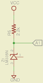
Temperature seems an obvious thing to measure, so a bit of rummaging disgorged a classic LM335 temperature sensor that produce an output voltage directly calibrated in Kelvin at 10 mV/K: room temperature runs 296 K = 2.96 V. Nothing could be easier than this:
LM335 Temperature Sensor
The downside: a 1 °C temperature change corresponds to only 10 mV, which is barely two LSB of the Arduino ADC. In round numbers, a 1 °F change = 1 LSB, which doesn’t leave much room for measurement noise. I average five successive readings, which may be excessive, but the result seems stable enough:
For better accuracy, you must measure VCC on the Arduino board and plug that into the AVREF constant, because the ADC reference voltage comes from the power supply. If you’re powering the Arduino from a USB port, then don’t bother worrying about analog conversion accuracy, because VCC depends on which PC you use, the USB cable length, what load current you draw from the regulator, and probably the phase of the moon.
The magic number 100.0 converts 10 mV/K to K.
The four character DL1414 LED display works well enough for the kind of temperatures you might find around a human being and, if you have an LED bargraph display, you may as well throw that into the mix, too.
LM335 Temperature Sensor – 19 C
The bargraph has RRYYGGYYRR LEDs, so I scaled the temperature at 5 °C/bar and put 0 °C on the bottom of the display, which means 15-19 and 20-24 °C occupy the green bars in the middle. Fingertip temperatures light up the two yellow bars and body heat gets you into the red, so it’s a reasonable display. Just to show it works, here’s a closer look (0 °C is on the right, but you can reverse that easily enough):
LM335 Temperature Sensor – 25 C
The Arduino source code:
// LM335 Temperature sensor sensor
// Ed Nisley - KE4ANU - November 2012

//#include <stdio.h>
//#include <math.h>

//----------
// Pin assignments

const byte PIN_TEMPERATURE = A1;			// Temperature sensor - LM335 = 10 mV/K

const byte PIN_MOSI = 8;			// data to shift reg
const byte PIN_SCK  = 6;			// shift clock to shift reg
const byte PIN_RCKB  = 7;			// latch clock for LED Bargraph
const byte PIN_RCKC  = 12;			// latch clock for LED character display

const byte PIN_HEARTBEAT = 13;				// DO - Arduino LED

//----------
// Constants

const int UPDATEMS = 1000;					// update LEDs only this many ms apart

const float AVREF = 4.94;					// Arduino analog reference
const float KTOC = -273.2;					// Kelvin to Centigrade offset

const float BARSCALE = 5.0;					// degrees per bar increment

#define TCCRxB 0x02							// Timer prescaler

#define LED_SIZE		4				// chars per LED
#define LED_DISPLAYS	1				// number of displays
#define LED_CHARS		(LED_DISPLAYS * LED_SIZE)

union DL1414_ {
	word ShiftWord;				// word overlay
	struct {					// bitfield sent to the display
	unsigned int Addr:2;
	unsigned int NotWrite:1;
	unsigned int Ctl3_7:5;			// unused bits
	unsigned int Data:7;
	unsigned int Data7:1;			// unused bit
	} ShiftBits;
};

//----------
// Globals

int Temperature, BaseTemperature;

word LEDBits;

char LEDCharBuffer[LED_CHARS + 1] = "HELO";		// raw char buffer, can be used as a string

unsigned long MillisNow;
unsigned long MillisThen;

//-- Helper routine for printf()

int s_putc(char c, FILE *t) {
  Serial.write(c);
}

//-- Send bits to LED bar driver register

void SetBarBits(word Pattern) {

	shiftOut(PIN_MOSI,PIN_SCK,MSBFIRST,Pattern >> 8);
	shiftOut(PIN_MOSI,PIN_SCK,MSBFIRST,Pattern & 0x00ff);

	digitalWrite(PIN_RCKB,HIGH);
	digitalWrite(PIN_RCKB,LOW);

}

void PulsePinHigh(byte PinID) {
	digitalWrite(PinID,HIGH);
	digitalWrite(PinID,LOW);
}

//-- Write single char to DL1414

void WriteLEDChar(char Char,char CharID) {

	union DL1414_ DL1414;

	DL1414.ShiftBits.Data = Char & 0x7F;
	DL1414.ShiftBits.Addr = ~CharID & 0x03;		// reverse order of chars

	DL1414.ShiftBits.NotWrite = 1;				// set up data and address

	shiftOut(PIN_MOSI,PIN_SCK,MSBFIRST,DL1414.ShiftWord >> 8);
	shiftOut(PIN_MOSI,PIN_SCK,MSBFIRST,DL1414.ShiftWord & 0x00ff);
	PulsePinHigh(PIN_RCKC);

	//	delay(1000);

	DL1414.ShiftBits.NotWrite = 0;				// write the character

	shiftOut(PIN_MOSI,PIN_SCK,MSBFIRST,DL1414.ShiftWord >> 8);
	shiftOut(PIN_MOSI,PIN_SCK,MSBFIRST,DL1414.ShiftWord & 0x00ff);
	digitalWrite(PIN_RCKC,HIGH);
	PulsePinHigh(PIN_RCKC);

	//	delay(1000);

	DL1414.ShiftBits.NotWrite = 1;				// disable write

	shiftOut(PIN_MOSI,PIN_SCK,MSBFIRST,DL1414.ShiftWord >> 8);
	shiftOut(PIN_MOSI,PIN_SCK,MSBFIRST,DL1414.ShiftWord & 0x00ff);
	PulsePinHigh(PIN_RCKC);

	//	delay(1000);

}

void WriteLEDString(char *pString) {

	for (byte i=0; (i < LED_CHARS) && *pString; ++i)
		WriteLEDChar(*pString++,i);

	return;
}

//-- Sample temperature with a dab of averaging

#define TAVG 5

float ReadLM335(byte Pin) {
float Kelvin;

	Kelvin = (float)analogRead(Pin);
	for (byte i = 1; i < TAVG; i++)
		Kelvin += (float)analogRead(Pin);

	return Kelvin * (100.0 * AVREF) / (TAVG * 1024.0);
}

//------------------
// Set things up

void setup() {
  pinMode(PIN_HEARTBEAT,OUTPUT);
  digitalWrite(PIN_HEARTBEAT,LOW);	// show we arrived

//  TCCR1B = TCCRxB;					// set frequency for PWM 9 & 10
//  TCCR2B = TCCRxB;					// set frequency for PWM 3 & 11

  pinMode(PIN_MOSI,OUTPUT);
  digitalWrite(PIN_MOSI,LOW);

  pinMode(PIN_SCK,OUTPUT);
  digitalWrite(PIN_SCK,LOW);

  pinMode(PIN_RCKB,OUTPUT);
  digitalWrite(PIN_RCKB,LOW);

  pinMode(PIN_RCKC,OUTPUT);
  digitalWrite(PIN_RCKB,LOW);

  Serial.begin(9600);
  fdevopen(&s_putc,0);				// set up serial output for printf()

  printf("Temperature sensor - LM335\r\nEd Nisley - KE4ZNU - November 2012\r\n");

  BaseTemperature = KTOC + ReadLM335(PIN_TEMPERATURE);

  WriteLEDString(LEDCharBuffer);

  LEDBits = 0x5555;
  SetBarBits(LEDBits);

  printf("Base Temperature: %d C\n",(int)BaseTemperature);

  delay(1000);

  MillisThen = millis();

}

//------------------
// Run the test loop

void loop() {

	MillisNow = millis();

	if ((MillisNow - MillisThen) > UPDATEMS) {
		digitalWrite(PIN_HEARTBEAT,HIGH);

		Temperature = KTOC + ReadLM335(PIN_TEMPERATURE);

		printf("Temperature: %d C\n",(int)Temperature);

		LEDBits = 0x0200 >> (1 + (int)(Temperature/BARSCALE));	// move upward on display!
		SetBarBits(LEDBits);

		sprintf(LEDCharBuffer,"%-3dC",(int)Temperature);
		WriteLEDString(LEDCharBuffer);

		digitalWrite(PIN_HEARTBEAT,LOW);

		MillisThen = MillisNow;
	}

}
Any gadget goes better with a knob and what better knob than one with detents all the way around? This one even has a push-on momentary switch on the shaft, so you can switch gain / change modes / control power while turning:
Quadrature Knob with Push Switch
Using the Arduino’s internal pullups means you just plug the wires into the header sockets and it works:
Quadrature Knob and Switch – breadboard
The code uses the same interrupt-driven state machine I described there to avoid glitches and twitches. The test code dumps the accumulated knob rotation count and switch state out the serial port:
Yes, you (well, I) can spin the knob fast enough to accumulate a few counts between the 10 ms updates and it will return to zero at the same physical location, so it’s not losing any counts in the process.
Attaching a linear Hall effect sensor to an Arduino doesn’t require much effort at all:
Linear Hall Sensor
Despite what I observed on that breadboard lashup, the output will need a load resistor (output-to-ground, across pins 3 and 2) if there’s no internal constant-current sink; anything around 10 kΩ should suffice. The one I have works fine with or without the resistor; I added a 10 KΩ resistor that’s not shown here. The output voltage does, as you’d expect, change slightly with the resistor in place.
The sensor lives on a different part of the same breadboard now:
49E Linear Hall Effect Sensor – breadboard
The test code drives the RGB LED strip: red for positive field strength and blue for negative. The maximum and minimum values track the extremes, for plenty of color regardless of how weak a magnet it sees. It works great with the one on my fingernail… and random screwdrivers, digital calipers, scissors, and suchlike.
The OpenSCAD source code:
// Hall sensor
// Ed Nisley - KE4ANU - November 2012

//----------
// Pin assignments

const byte PIN_RED = 9;				// PWM - LED driver outputs +active
const byte PIN_GREEN = 10;
const byte PIN_BLUE = 11;

const byte PIN_FIELD = A0;			// Hall sensor input, 0 field = 2.5 v, more or less

const byte PIN_HEARTBEAT = 13;		// DO - Arduino LED

//----------
// Constants

const int UPDATEMS = 5;					// update LEDs only this many ms apart

#define TCCRxB 0x02						// Timer prescaler

//----------
// Globals

float FieldHigh, FieldLow, FieldRange, FieldBase, Field;

byte Red,Blue,Green;

unsigned long MillisNow;
unsigned long MillisThen;

//-- Helper routine for printf()

int s_putc(char c, FILE *t) {
  Serial.write(c);
}

int sign_float(float val) {
	if (val < 0.0)
		return -1;
	else if (val > 0.0)
		return 1;

	return 0;
}

//-- Sample magnetic field with a dab of averaging

#define FIELDAVERAGE 5

float ReadSensor(byte Pin) {
float Field;

	Field = (float)analogRead(Pin);
	for (byte i = 1; i < FIELDAVERAGE; i++)
		Field += (float)analogRead(Pin);

	return Field / (FIELDAVERAGE * 1024.0);
}

//------------------
// Set things up

void setup() {
  pinMode(PIN_HEARTBEAT,OUTPUT);
  digitalWrite(PIN_HEARTBEAT,LOW);	// show we arrived

  TCCR1B = TCCRxB;					// set frequency for PWM 9 & 10
  TCCR2B = TCCRxB;					// set frequency for PWM 3 & 11

  pinMode(PIN_RED,OUTPUT);
  analogWrite(PIN_RED,0);			// force gate voltage = 0

  pinMode(PIN_GREEN,OUTPUT);
  analogWrite(PIN_GREEN,0);

  pinMode(PIN_BLUE,OUTPUT);
  analogWrite(PIN_BLUE,0);

  Serial.begin(9600);
  fdevopen(&s_putc,0);				// set up serial output for printf()

  printf("Hall effect sensor\r\nEd Nisley - KE4ZNU - November 2012\r\n");

  Field = ReadSensor(PIN_FIELD);	// prime the field sensor pump
  FieldBase = Field;
  FieldHigh = 1.1 * Field;
  FieldLow = 0.9 * Field;
  FieldRange = FieldHigh - FieldLow;

  printf("Average field: %d\n",(int)(1024.0 * Field));

  MillisThen = millis();

}

//------------------
// Run the test loop

void loop() {

	MillisNow = millis();

	if ((MillisNow - MillisThen) > UPDATEMS) {
		digitalWrite(PIN_HEARTBEAT,HIGH);

		Field = ReadSensor(PIN_FIELD);
		FieldHigh = max(FieldHigh,Field);
		FieldLow = min(FieldLow,Field);
		FieldRange = FieldHigh - FieldLow;

//		printf("Field: %d\n",(int)(1024.0 * Field));

		switch (sign_float(Field - FieldBase)) {
			case -1:
				Blue = (byte)(255.0*(FieldBase - Field)/FieldRange);
				Red = 0;
				break;
			case 1:
				Red = (byte)(255.0*(Field - FieldBase)/FieldRange);
				Blue = 0;
				break;
			case 0:
				Red = Blue = 0;
				break;
			default:
				printf("Whoops!\n");
				delay(1000);
		}
		Green = 0;

		analogWrite(PIN_RED, Red);
		analogWrite(PIN_BLUE,Blue);
		analogWrite(PIN_GREEN,Green);

		digitalWrite(PIN_HEARTBEAT,LOW);

		MillisThen = MillisNow;
	}

}