Ed Nisley's Blog: Shop notes, electronics, firmware, machinery, 3D printing, laser cuttery, and curiosities. Contents: 100% human thinking, 0% AI slop.
A brace of cheap HD USB cameras may improve the scenery around here during video meetings. They were $16, marked down from an absurd $130:
HD USB Camera price history
Some poor schlubs certainly dropped more than twice the price of a Genuine Logitech camera on these critters, but a nearly total lack of demand must have had some effect.
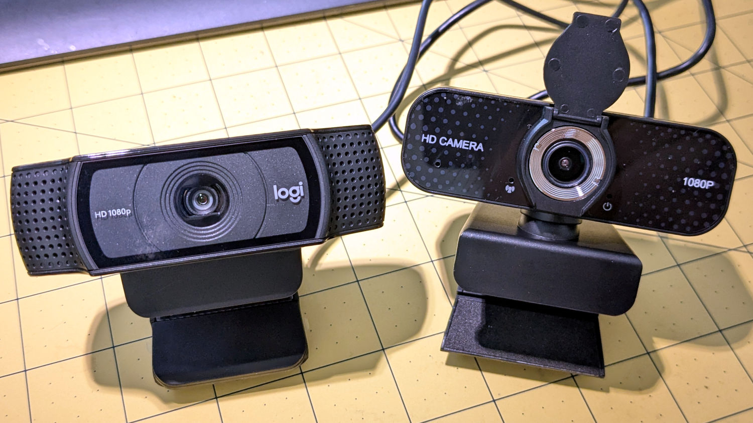
They do take their stylin’ cues from Logitech, although the speckled pattern on a shiny plastic sheet is amusing:
HD USB Camera – styling vs Logitech C920
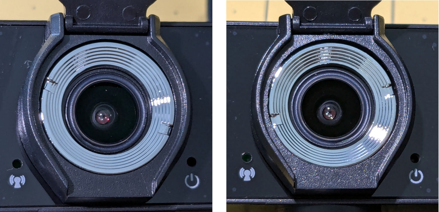
Unsurprisingly, the lens is fixed / manual focus. What looked like focus rings were in different positions on the two cameras:
HD USB Camera – lens focus notches
It turns out the rings were not glued in place, perhaps because they have absolutely no effect on the camera’s focus. Maybe there’s another camera model where they rotate the lens in a threaded socket, but this ain’t that.
The front panel has three pores:
A red Power LED is always on when it’s plugged in
A green On the air LED lights up when the camera is selected; I have no idea what the WiFi-ish glyph is supposed to represent
The “advanced noise canceling microphone” sits behind a pore offscreen left; the claim seems dubious.
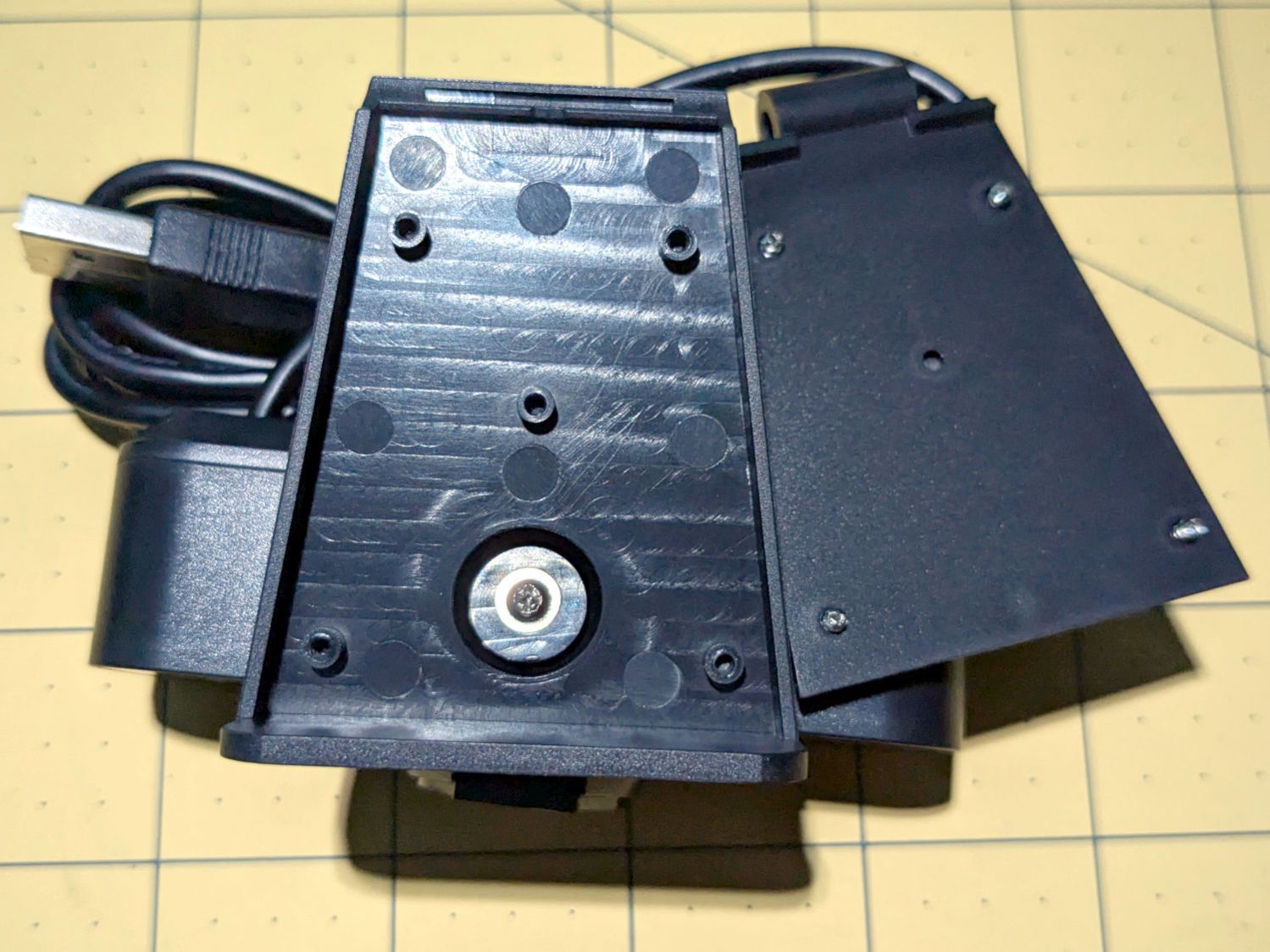
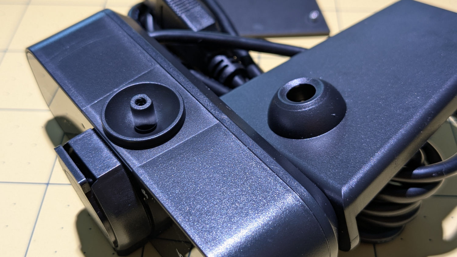
Because these may go into smaller spaces, I dismantled the base to see what was involved. Most of the screws lie underneath thin foam sheets:
HD USB Camera – ball mount interior
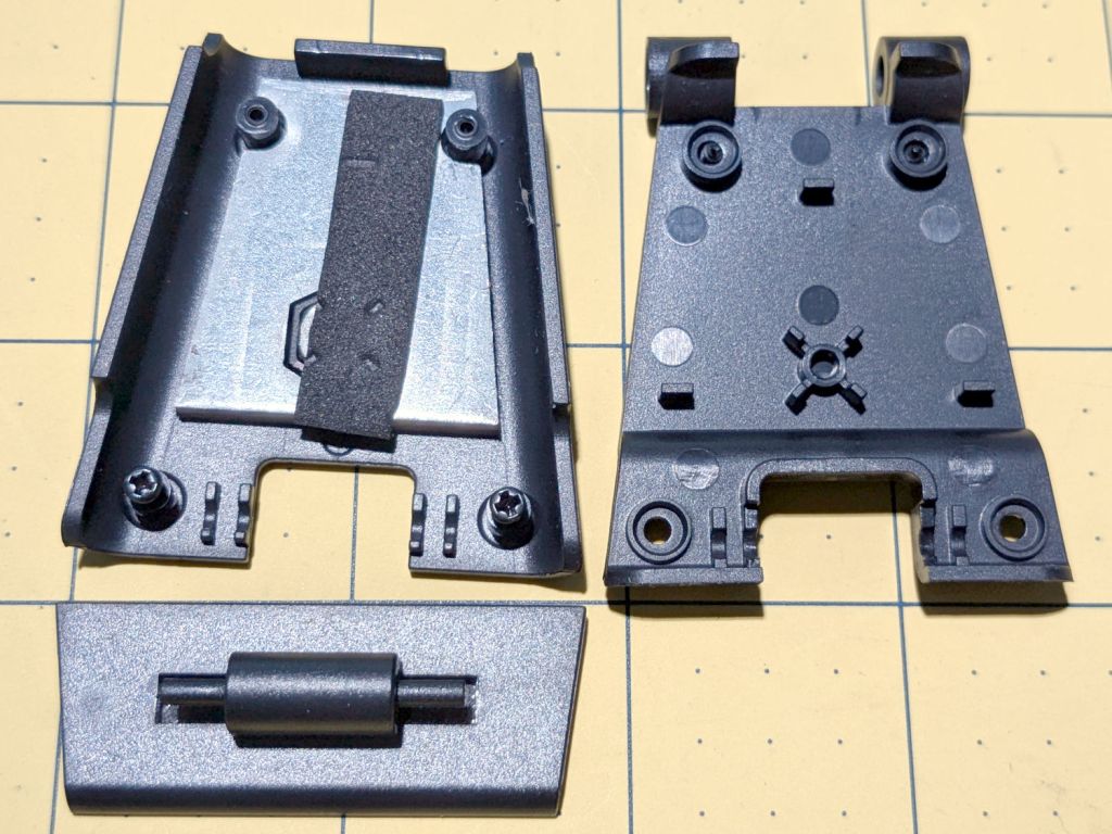
The lower plate has a tripod mount and a folding bracket:
HD USB Camera – baseplate interior
The camera body has a ball mount with a few degrees of movment:
HD USB Camera – ball mount detail
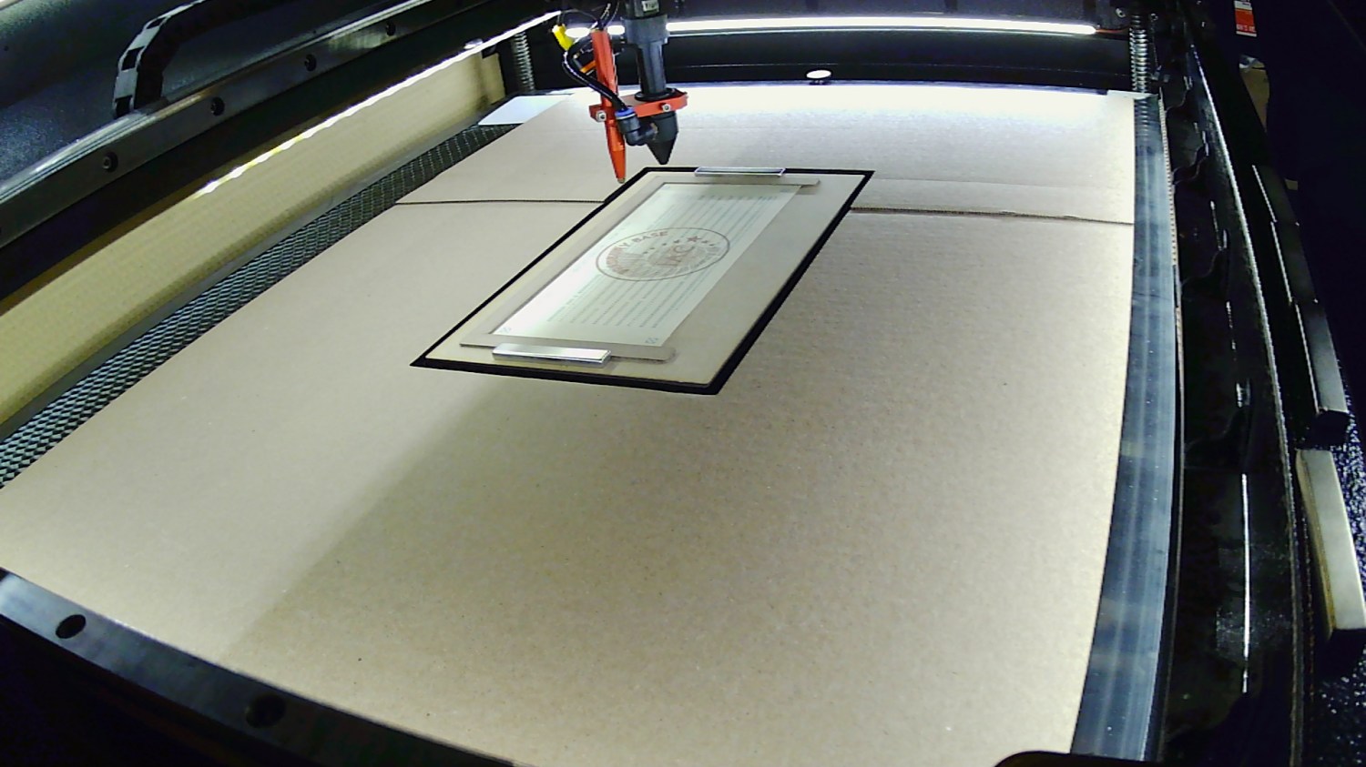
Reassembled and stuck inside the laser cabinet with some good double-sided foam tape, it definitely produces a better image than the previous camera:
Platform camera view
Whatever noise cancellation the mic may provide is irrelevant in there: nobody’s listening.
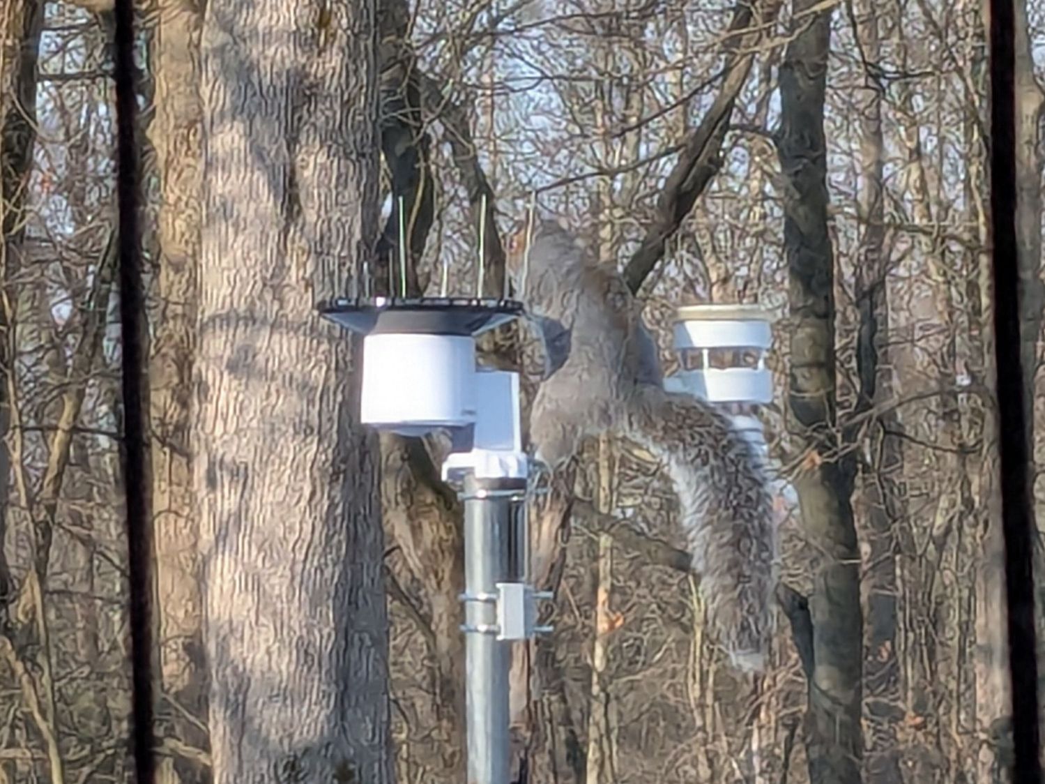
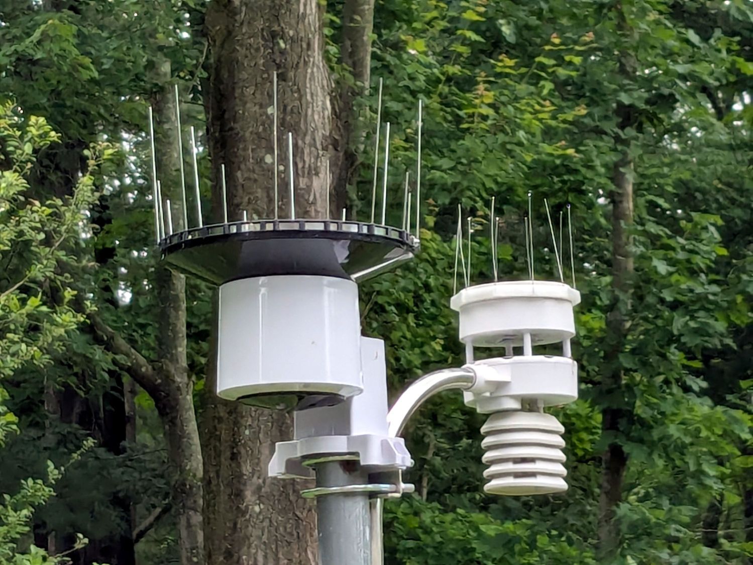
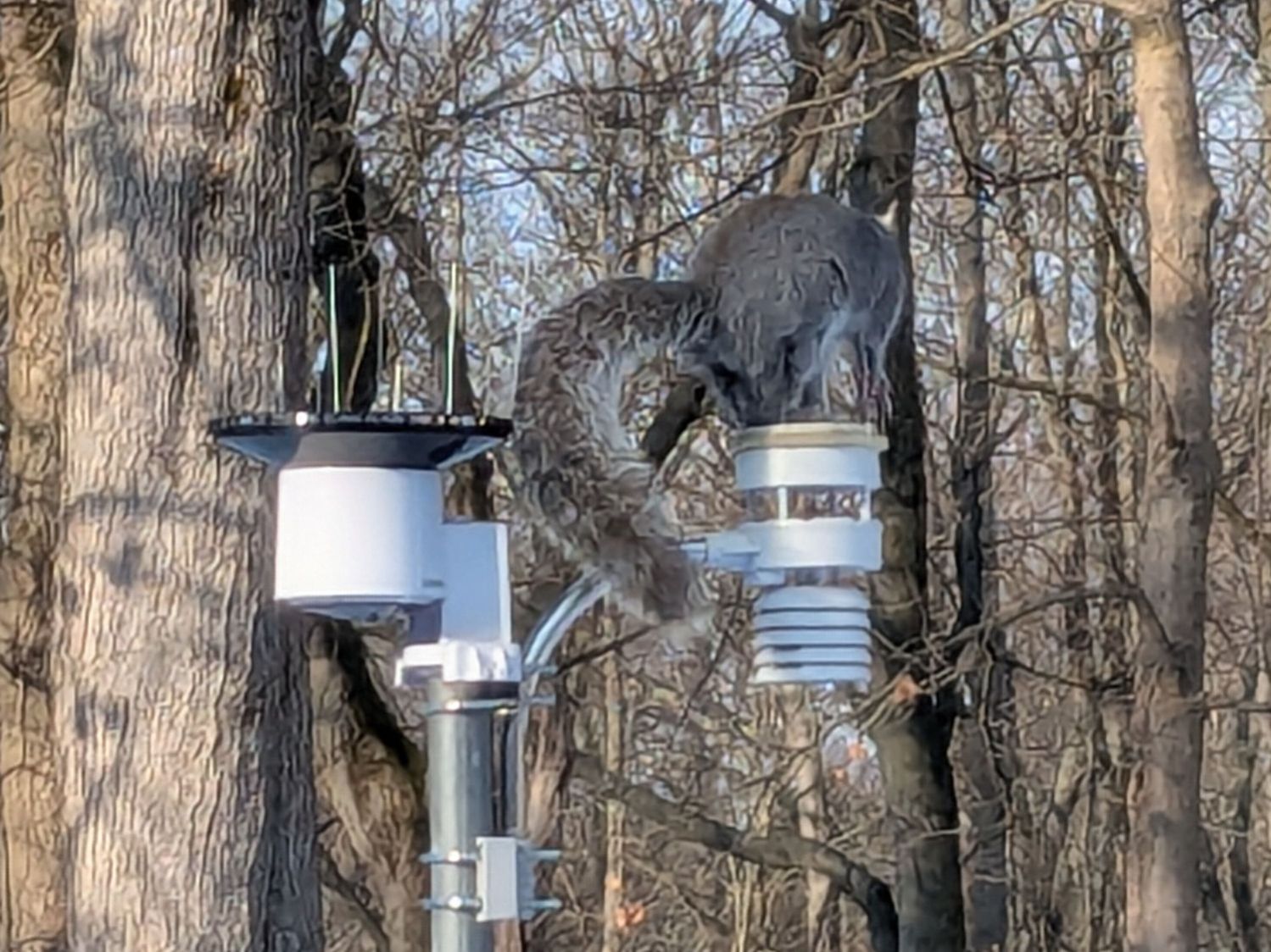
Chickadees can perch between the wires and squirrels apparently just ignore the sharp ends:
Squirrel on WS-5000 Anemometer spikes
No matter how hard that squirrel looked, there were no nuts to be found anywhere in that tree. Moments later it ran down the pole and loped across the yard to forage under the seed feeder.
The terrible picture quality comes from a Pixel 6a phone camera zoomed all the way tight. I want an optical telephoto lens built into the phone, but those phones seem intended to reduce the risks of having severe wallet overpressure.
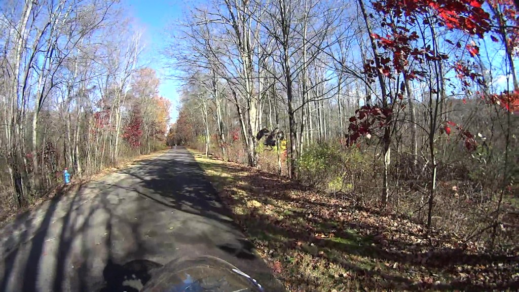
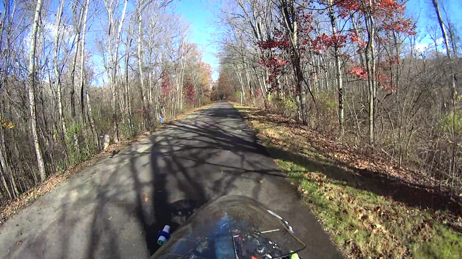
(The last three digits in the caption tick along at 60 frame/s. Opening each iamge in a new tab will let you embiggen the details, although the images aren’t all that great.)
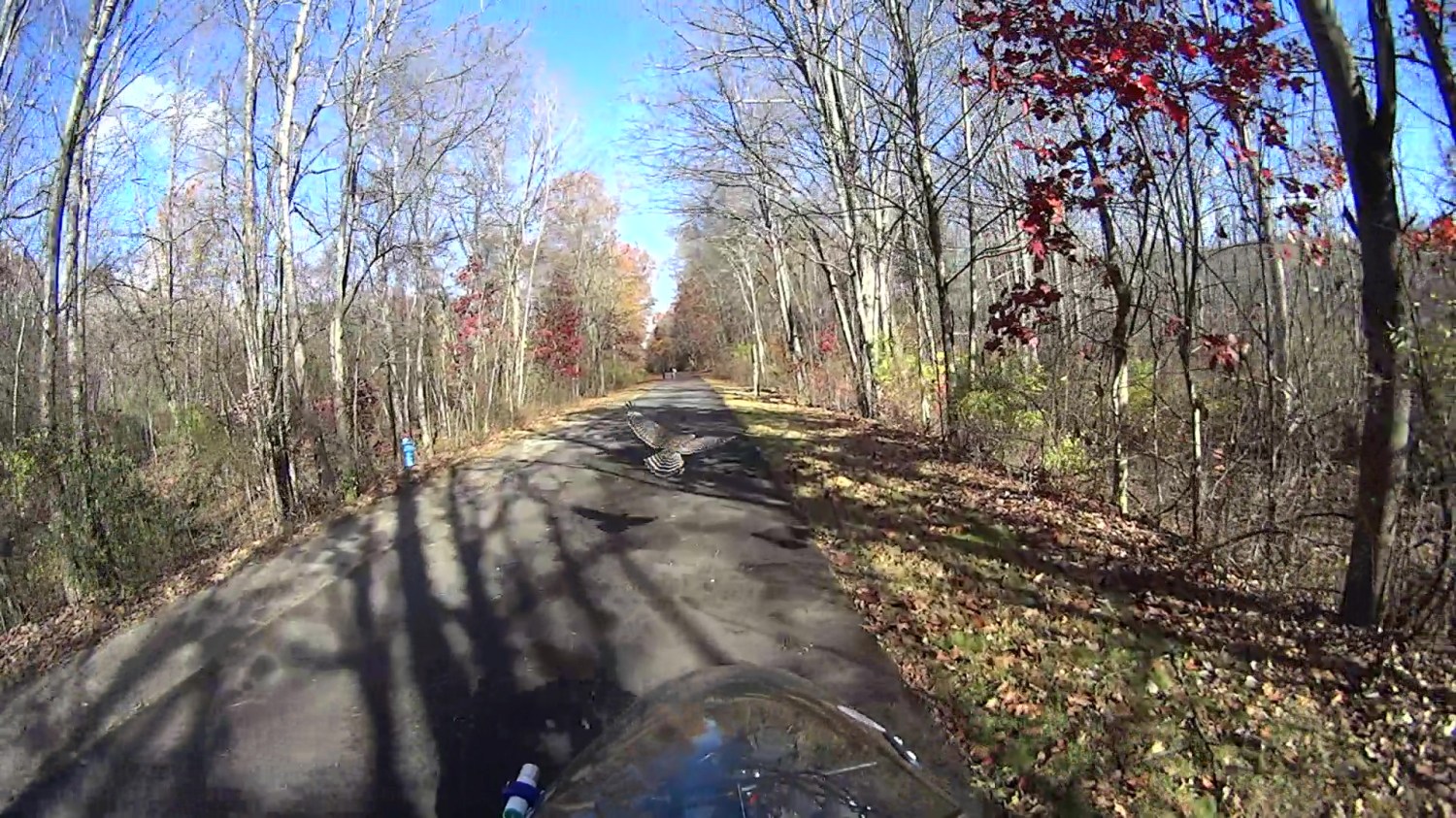
The second wingbeat, over on the left, is more visible as the hawk lifts off:
Hawk with snake 2025-11-04 – 112
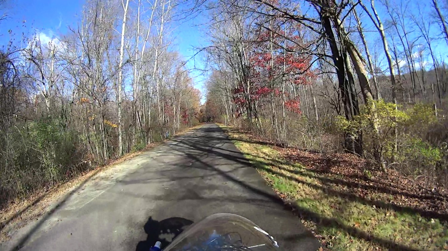
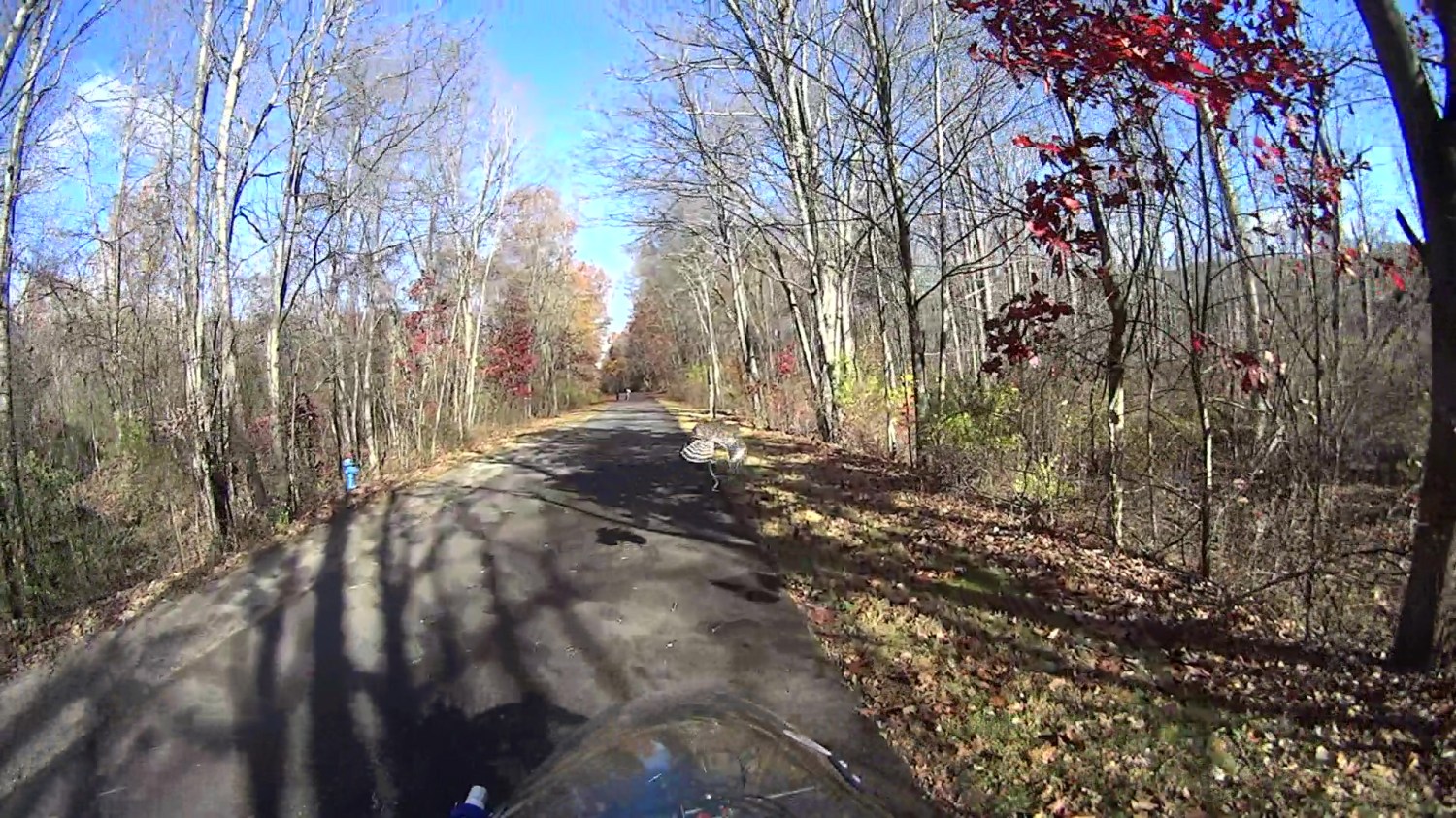
This was about when I figured out what was going on:
Hawk with snake 2025-11-04 – 151
A hawk can easily outfly me!
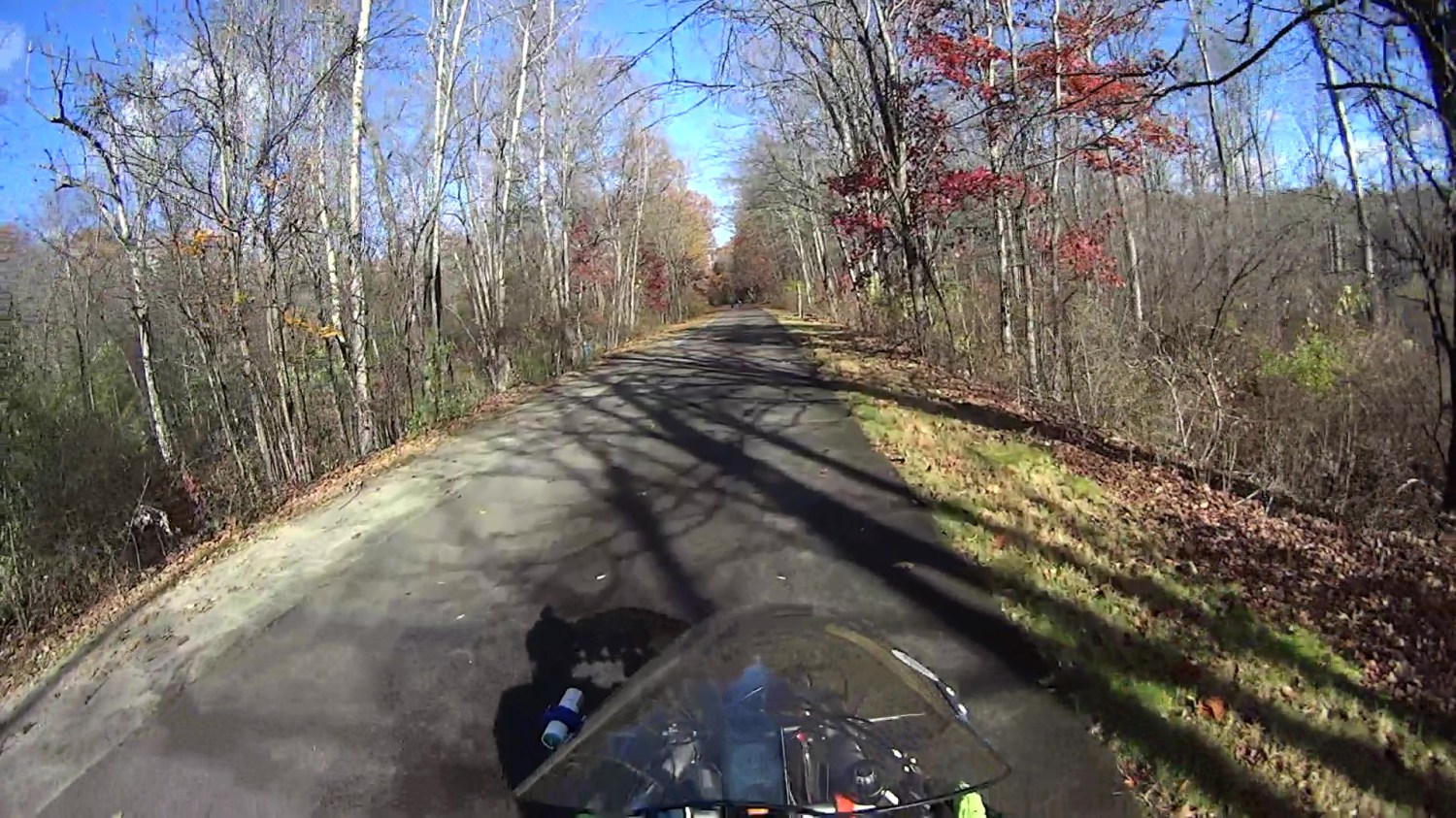
Hawk with snake 2025-11-04 – 207
The snake dangling from the hawk’s talons didn’t see it coming, either:
Hawk with snake 2025-11-04 – 213
Up and away!
Hawk with snake 2025-11-04 – 225
About 2.3 s of elapsed time: plenty for a hawk and not nearly enough for me. Or the snake, for that matter.
The laser-engraved guide lines confused GIMP’s edge detection to no end.
It came from a large sheet of 1 mm acrylic, formerly a poster cover, bearing scars of its long history in the “might be useful someday” stash. I wondered if I could remove enough scratches and scuffs to ease GIMP’s workload.
Stipulated: I am a cheapskate.
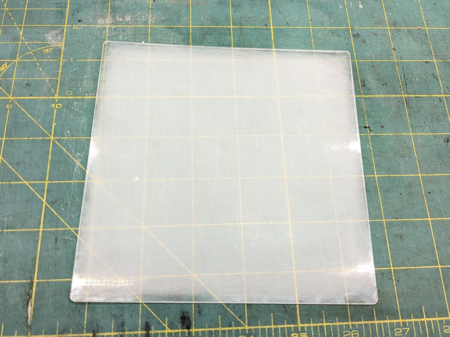
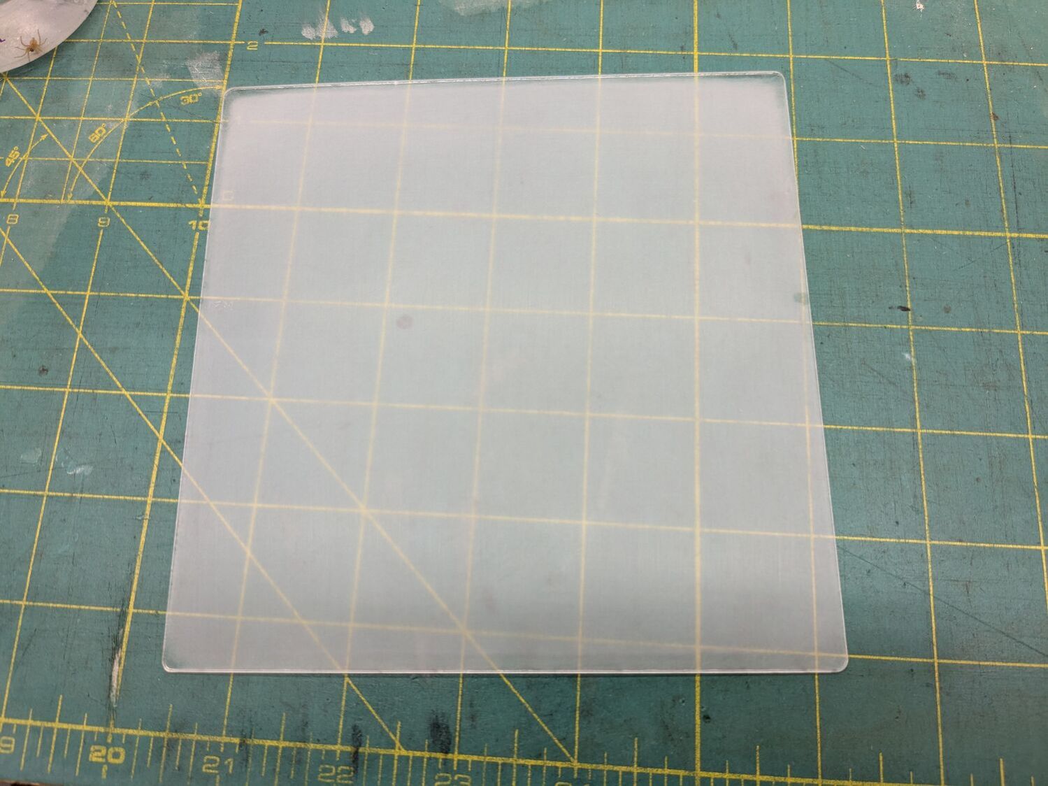
Laser-cut a suitable sheet and sand both sides with 220 grit paper to what looked like a uniform surface:
Acrylic polishing – 220
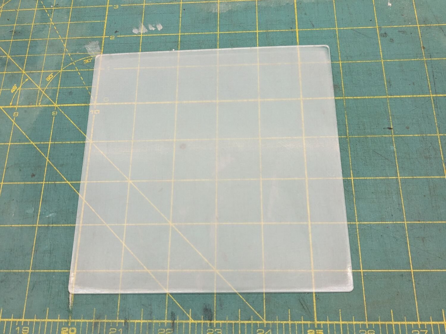
Continue scrubbing with 400, 800, 1000, 1500, and 3000 grit papers:
Acrylic polishing – 3000
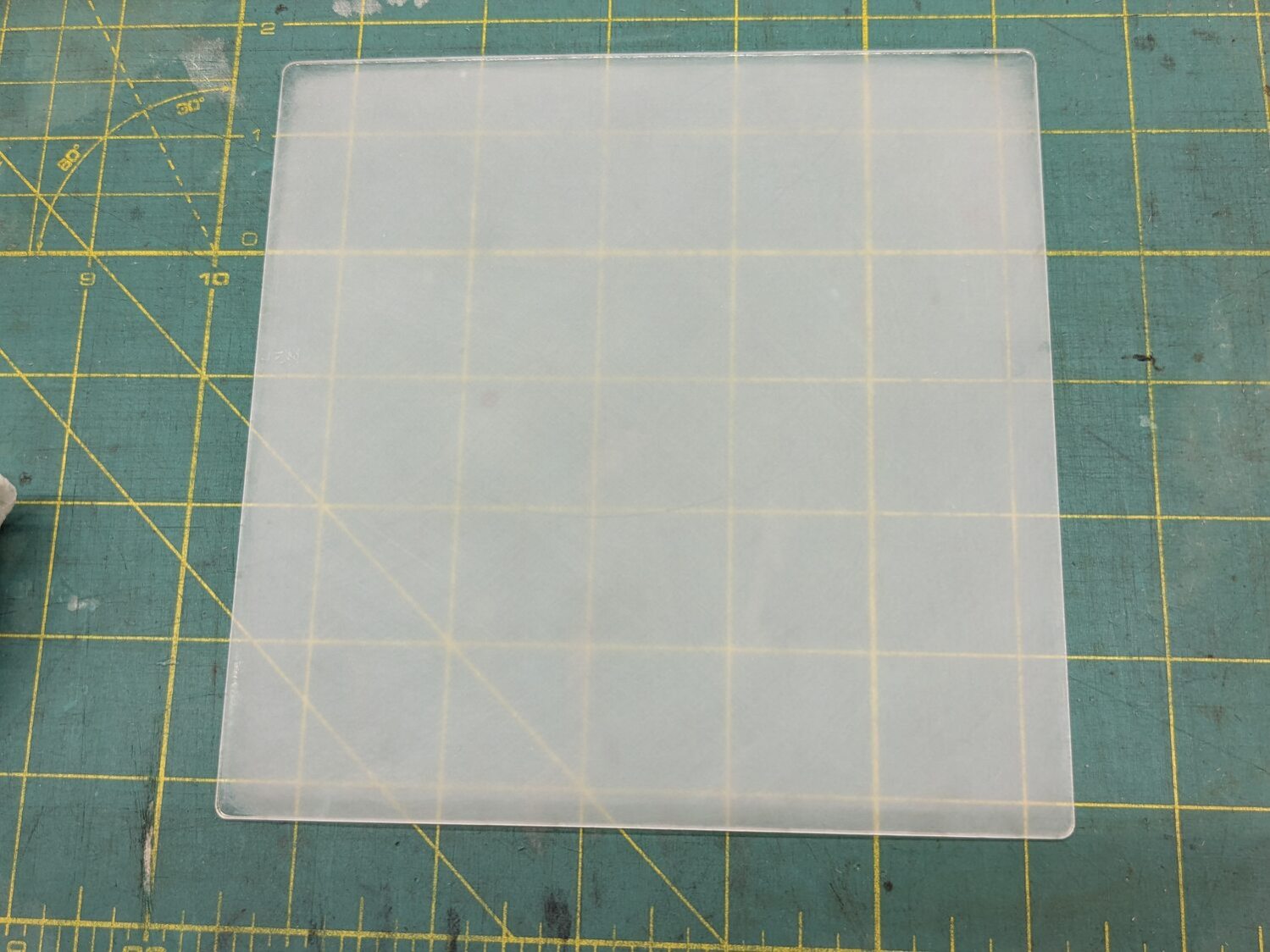
Massage it with Novus Polish 3, 2, and 1:
Acrylic polishing – Novus 1
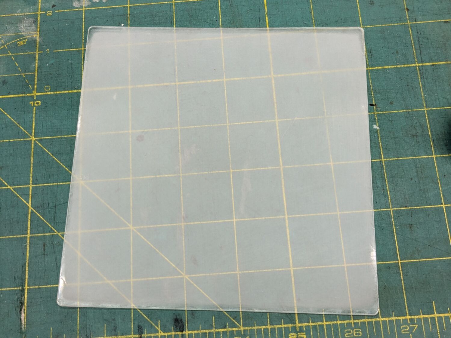
At best, it’s more translucent than transparent and definitely not an optical-quality polishing job:
Acrylic polishing – translucency
Fortunately, I need not care about the edges, because it goes in a square frame with a circular cutout.
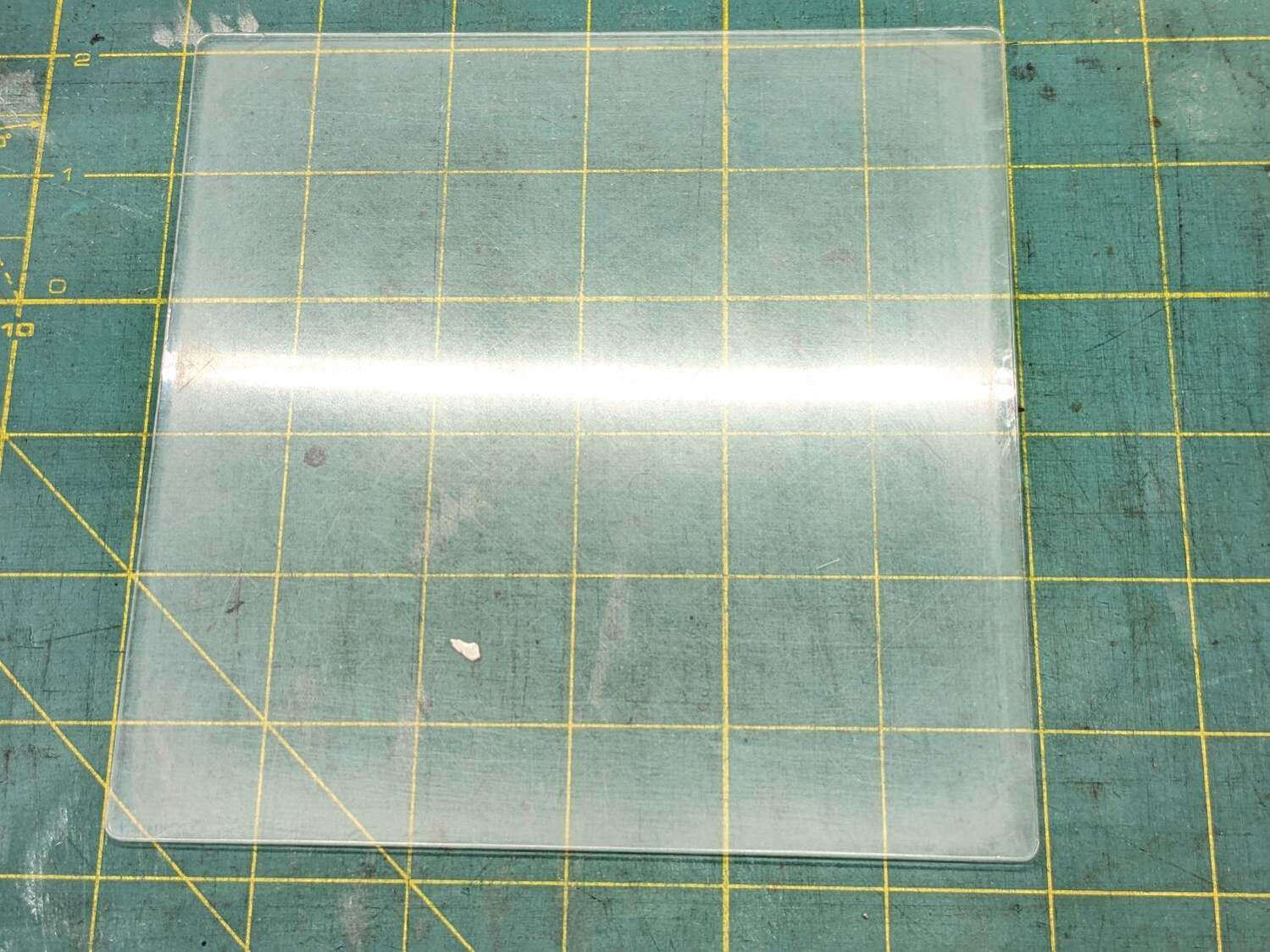
Tape it into that cardboard frame, scan it against a black background, and blow out the contrast to show I should have started with 100 grit paper and paid more attention to that “uniform surface” thing:
Acrylic polishing – scratches
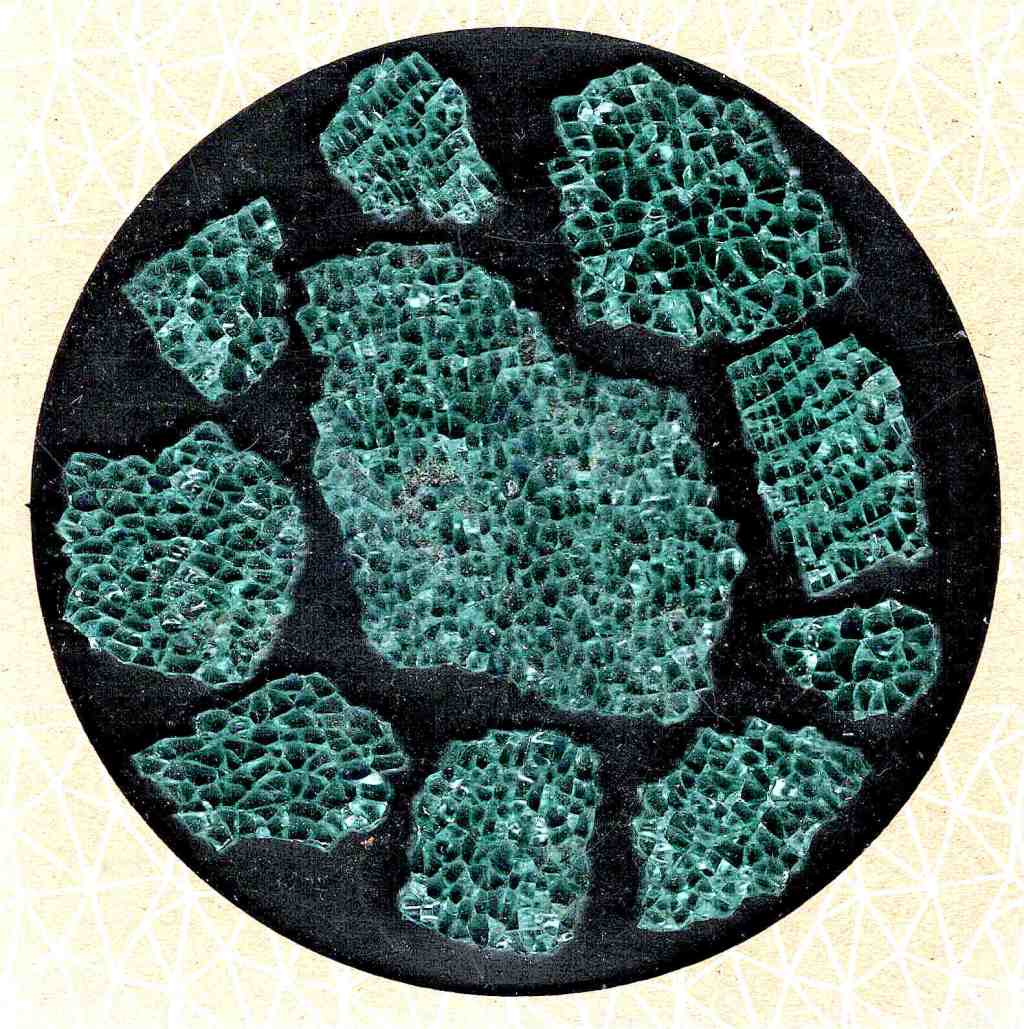
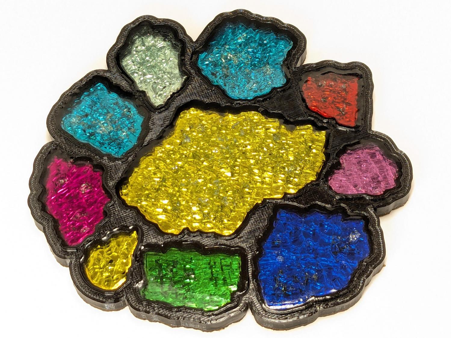
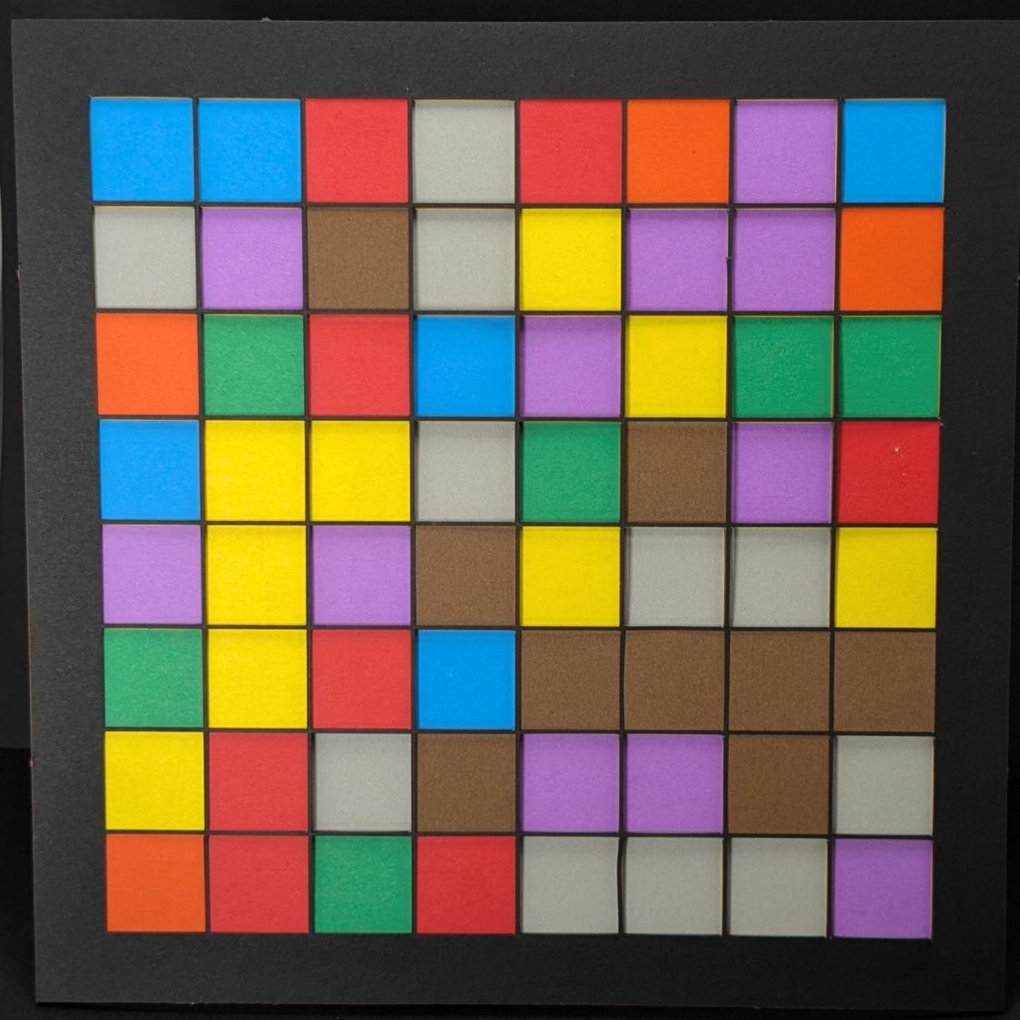
In use, though, it doesn’t look all that bad:
Fragment layout – 5in Set B – scan tweaked
Come to find out those glittery cracks between all the cuboids still confuse GIMP’s edge detection, but at least hand-tracing the outline is easier without all the lines.
The entire “polishing” series as a slideshow for your amusement:
Thresholding the distance from a randomly chosen point creates circular rainbows:
CenterPoint = (choice(range(args.width)),choice(range(args.height)))

CellMatrix = [[math.hypot(x - CenterPoint[X],y - CenterPoint[Y])
                for y in range(args.height)]
                for x in range(args.width)]

dmax = max(list(chain.from_iterable(CellMatrix)))

LayerThreshold = (ThisLayer/Layers)*dmax
The Python program generates one SVG image file representing a single layer, as determined by the Bash one-liner invoking it:
for i in {00..16} ; do python Layers\ -\ 200mm.py > Test_$i.svg ; done
In real life you’d also use a different random seed for each set of layers, but that’s just another command line optIon.
Import those 17 SVG images into LightBurn, arrange neatly, snap each one to the middle of the workspace grid (and thus the aligned template), then Fire The Laser:
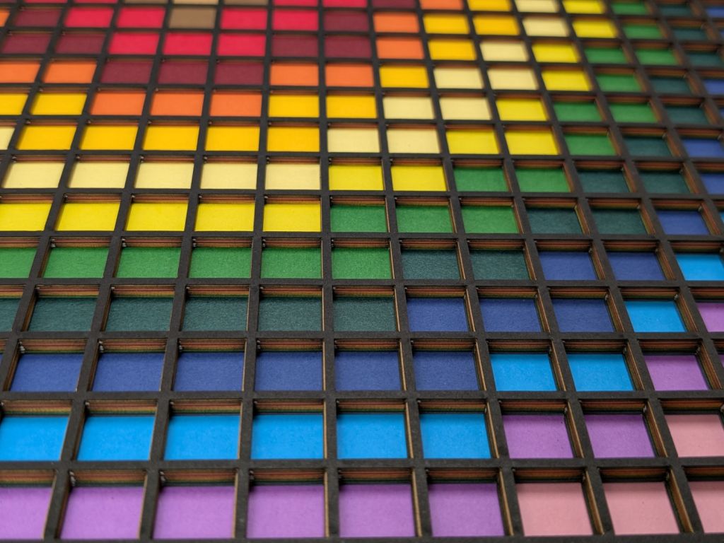
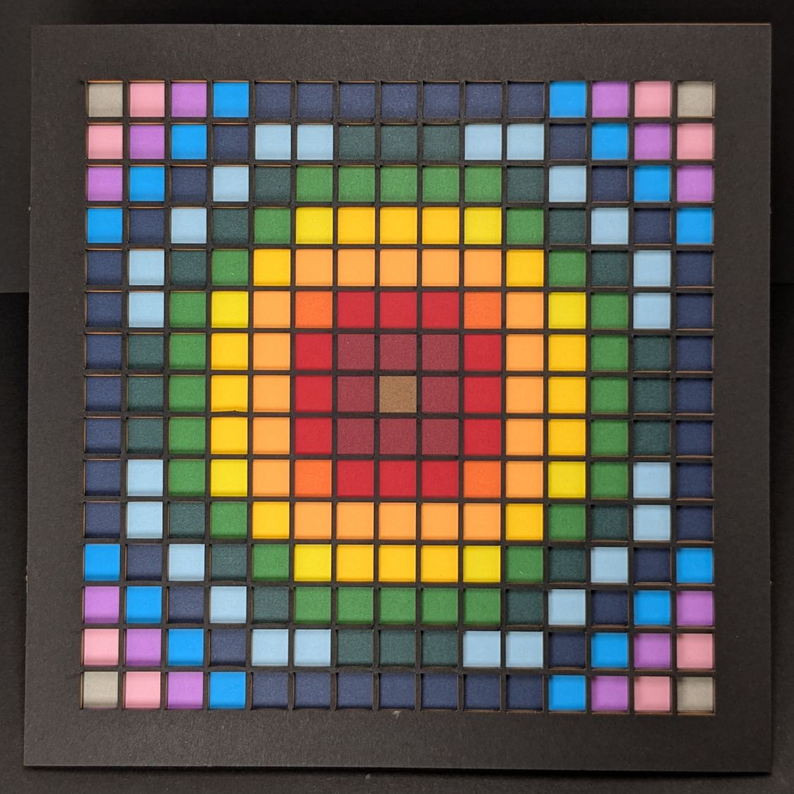
Feeding paper into the laser in rainbow (actually, heavily augmented / infilled EIA color code) order, plus the black mask, produces the aforementioned pleasing result:
Layered Paper – rainbow oblique view
Glue the sheets in the assembly fixture:
Layered Paper – gluing fixture side view
The white layer is uncut, other than the four alignment holes (with a rivnut poking up) and its binary layer number (16, backwards because upside-down), and appears in only the farthest corners of the rainbow.
Protip: doing the stack upside-down means you smear glue stick on the hidden side of each sheet. If you avoid slobbering glue into the cut square holes, nothing can go wrong.
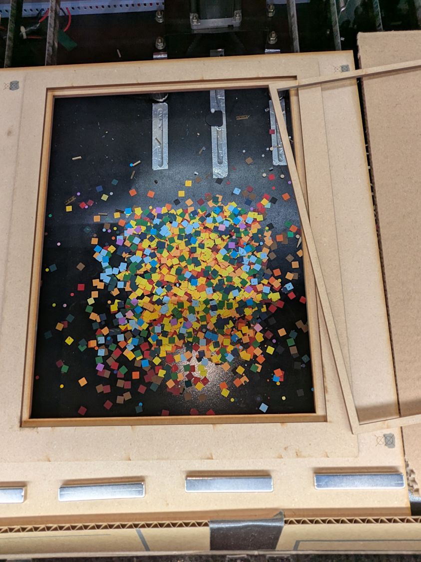
Making these things produces the happiest chip tray ever:
Layered Paper – rainbow chip tray
I swept half a dozen pictures worth of squares into a small box and gave it away to someone with a larger small-child cross-section than mine, whereupon a slight finger fumble turned the contents into a glitter bomb. Sorry ’bout that.
This file contains hidden or bidirectional Unicode text that may be interpreted or compiled differently than what appears below. To review, open the file in an editor that reveals hidden Unicode characters.
Learn more about bidirectional Unicode characters
# cut layer ID holes except on mask layer
if ThisLayer > 0:
    c = ((1,1))
    h = f'{ThisLayer:0{Layers.bit_length()}b}'
    for i in range(Layers.bit_length()):
        SheetEls.append(
            svg.Circle(
                cx=as_mm(SheetCenter[X] + c[X]*AlignOC[X]/2 - (i + 2)*AlignOD),
                cy=as_mm(SheetCenter[Y] + c[Y]*AlignOC[Y]/2),
                r=AlignOD/4 if h[-(i + 1)] == '1' else AlignOD/8,
                stroke=SheetCut,
                stroke_width=DefStroke,
                fill="none",
             )
        )
Filling the matrix of blocks with random numbers turned out to be a one-liner:
CellMatrix = [[randint(1,args.colors) for _ in range(args.height)] for _ in range(args.width)]
That matrix is a constant for all the layers, which is why you must feed the program the same random number seed to generate the layers.
Given the layer number and that matrix, deciding what to do for each hole is a walk through the cells:
MatrixEls = []                  # accumulates matrix cuts
for i in range(args.width):
    x =i*CellOC[X]
    for j in range(args.height):
        y = j*CellOC[Y]

        if ThisLayer == 0:                          # black mask
            s = HeavyCellCut
        elif ThisLayer < CellMatrix[i][j]:          # rest of sheets above color layer
            s = CellCut
        else:
            s = Tooling                             # at or below color layer

        MatrixEls.append(
            svg.Rect(
                x=as_mm(SheetCenter[X] - MatrixOA[X]/2 + x),
                y=as_mm(SheetCenter[Y] - MatrixOA[Y]/2 + y),
                width=as_mm(CellSize[X]),
                height=as_mm(CellSize[Y]),
                stroke=s,
                stroke_width=DefStroke,
                fill="none",
            )
        )
After accumulating all the other elements in similar lists, this creates and emits the entire SVG file to stdout:
The whole program has a bit more going on, but those are the high points.
Invoke the program with a Bash one-liner:
for i in {00..08} ; do python Layers.py --layernum=$i > Test_$i.svg ; done
That produces nine SVG image files that you import into LightBurn and arrange in a tidy array:
Layered Paper – Random Blocks – MVP – LightBurn import
I discovered that holding down the Shift key while importing the SVG files stacks them at the workspace origin (the upper-right corner for my machine) in the order of the file names, so clicking on the stack selects successive layers in the right order; just drop each one wherever you need it, then tidy the lineup.
The Python program sets the vector stroke colors using LightBurn palette values, so that LightBurn automagically assigns them to the appropriate layers. It turns out the black paper I used for the mask requires different speed / power values than the other colored paper.
I put the alignment features on a different layer than the matrix holes to make them more visible, even though they have the same speed / power values.
Align the template so the middle of the layer pattern is in the middle of the grid, then use LightBurn’s Print and Cut to align the template with the fixture on the laser platform:
Layered Paper – Random Blocks – MVP – template
Then the process requires just a few clicks per layer:
Drop a sheet of paper into the fixture
Click to select a layer layout
Ctrl-D to duplicate it
P to snap it to the middle of the grid
Alt-S to Fire The Laser
Del to delete that layer (which is why it’s a duplicate!)
Iterate until done!
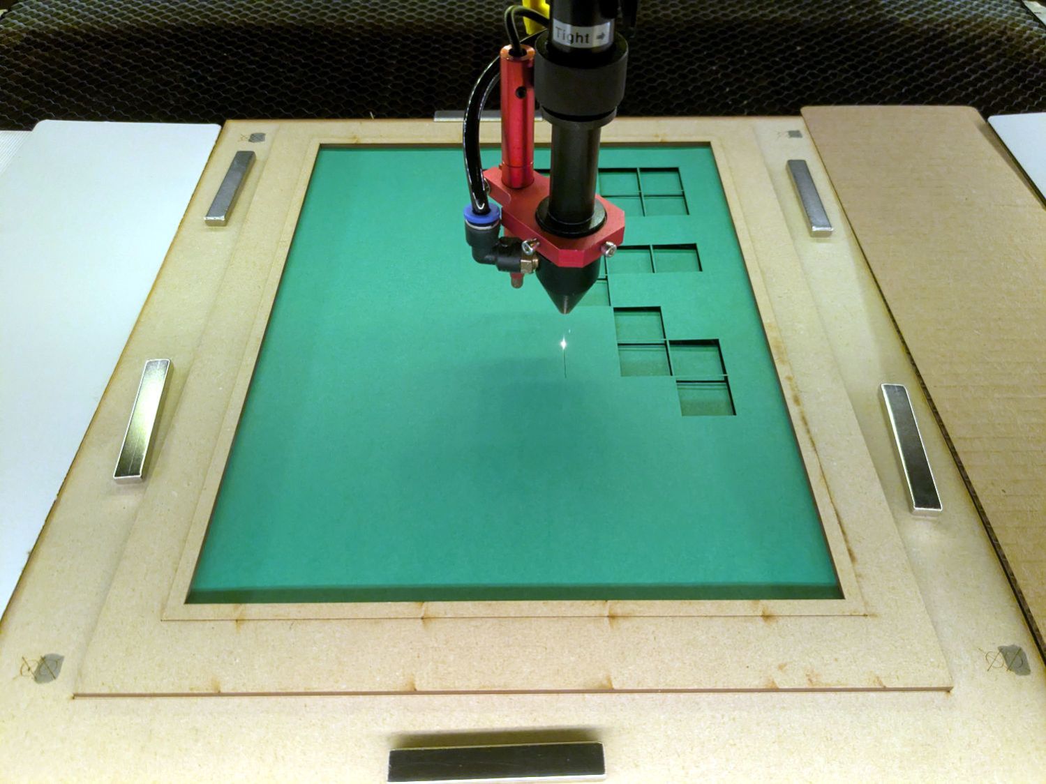
Which looks pretty much like you’d expect:
Layered Paper – Random Blocks – cutting
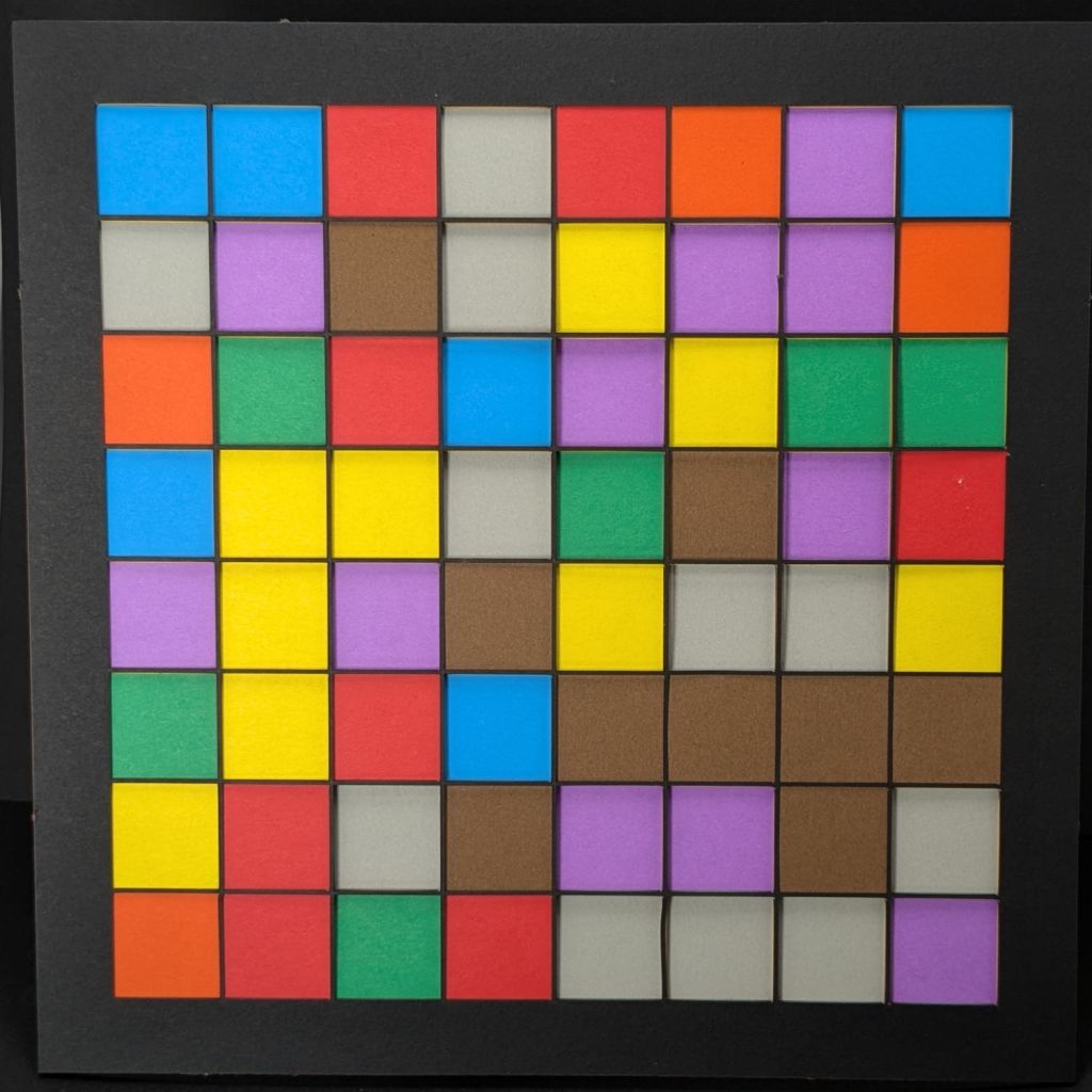
Take the stack of paper to the workbench, use an Xacto knife to cut the tabs holding the square into the Letter page, apply glue stick, stack in the fixture, and iterate to create a solid sheet with lots of holes:
Layered Paper – Random Blocks – MVP
More refinement is in order, but that’s the overview …
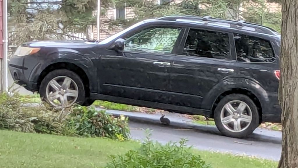
We’ve seen several new rabbits munching greenery in the back yard, but this little one may be studying auto repair under our neighbor’s car:
Rabbit – automotive hiding place
Unlike mice, even a small rabbit won’t take up residence in the air cleaner.
The weird granulated look comes from a Pixel 6a camera zoomed all the way tight through two layers of 1960-era window glass at an acute angle. The bad camera you have is always better than the good camera you don’t.