Ed Nisley's Blog: Shop notes, electronics, firmware, machinery, 3D printing, laser cuttery, and curiosities. Contents: 100% human thinking, 0% AI slop.
Follow the money: being a bank / credit card / fintech company, it’s safe to assume they sell your sensitive bits and have zero incentive to let you limit their actions in any way.
A week later, that part of their site remains broken, presumably as intended.
For reasons that surely made sense at the time, the Huion H610Pro (V2) tablet can recognize when it’s connected to an Android device’s USB port and enter a special mode where the stylus only responds in a phone-shaped portrait rectangle over on the left side:
Huion H610Pro (V2) Tablet – Android layout
There’s a Vulcan Nerve Pinch button push to force the tablet into Android mode if it doesn’t automagically get there on its own, but AFAICT there’s no way to force it out of Android mode.
It’s a USB 2.0 device, but I had plugged it into a USB 3.0 port on my desktop box, whereupon it would enter Android mode on pretty nearly every boot. The only way to coerce it back into normal mode was to unplug it, replug it, then manually run the xsetwacom incantation to restrict the coordinates to the portrait monitor.
I just discovered it works perfectly when plugged into one of the few USB 2.0 ports on the box.
Apparently, USB 3.0 ports keep the thing powered all the time, whereupon it doesn’t see the proper sequence of events (or, perhaps, sees the Android sequence) during the next boot. USB 2.0 ports don’t do that and it works fine all the time.
Just before midnight, the garage door opened, but, being early-to-bed folks, it wasn’t either of us. I pulled my fingernails out of the ceiling, padded out to the garage, verified there was nobody (not even a critter more substantial than a spider) inside, closed the door with the hardwired control button on the wall, and went back to bed. An hour later, the door opened again, then tried to take a bite out of me when I walked under it.
I pulled the opener’s plug, yanked its emergency release latch, lowered the door, and returned to bed; it was not a restful night.
The key to the diagnosis came from the little yellow LED on the back of the opener, just above the purple LEARN button:
Craftsman Garage Opener – indicator LED
In addition to indicating various programming states, it also lights when the opener’s radio receives a transmission from one of the remote controls. The LED was flickering continuously, showing that something was hosing the receiver with RF.
We have three remotes: one in the car, one on my bike, and one in the back room overlooking the garage. None of them worked reliably, suggesting the RF interference was clobbering their transmissions.
Disabling the remotes by removing their batteries (which were all good) also stopped the interference. Reinstalling the batteries one-by-one identified the rogue opener:
Craftsman Garage Opener – remote innards
The slip of paper let me isolate the battery terminal and stick a milliammeter in the circuit, which showed the remote was drawing about 1.5 mA continuously. I thought one of the pushbutton switches had gone flaky, but swapping an unused one for the main door switch had no effect.
I lost track of which remote it was, but it lived in the car or the back room for all its life, so it hasn’t suffered extreme environmental stress. I have no idea why it would fail late one night, although I admit to not monitoring the LED on a regular basis. For whatever it’s worth, in the weeks leading up to the failure, activating the opener sometimes required two pokes at the remote, but nothing bad enough to prompt any further investigation.
A new cheap knockoff remote arrived in few days and it’s all good.
Protip: different openers, even from the same company, use different RF frequencies. For Craftsman openers, the color of the LEARN button is the key to the frequency; purple = 139.53753 MHz.
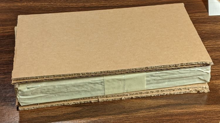
For reasons not relevant here, I sent the Beckman DM73 to a good home in Europe. Having some experience with the brutality applied to innocent packages by various package-delivery organizations, I filled a Priority Mail Flat Rate Small Box with a solid block of corrugated cardboard:
DM73 – cardboard armor
One inner layer has a cutout for the manual:
DM73 – Operator Manual package
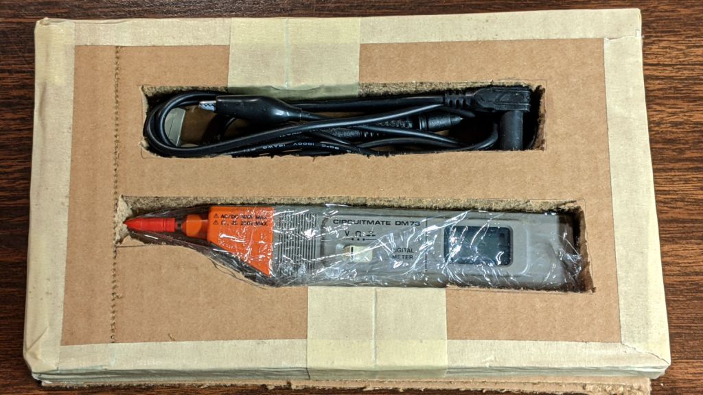
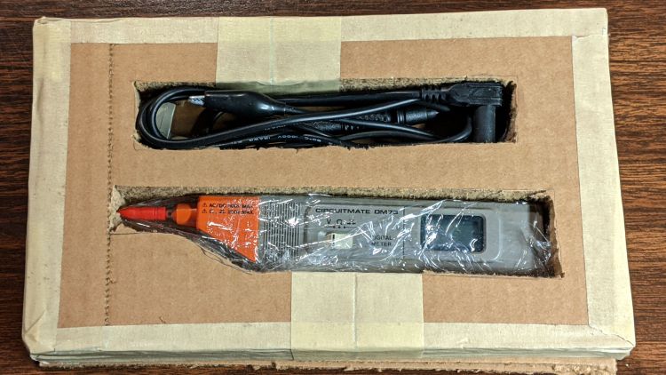
The meter and its leads tuck into form-fitting cutouts:
Beckman DM73 – cardboard packing
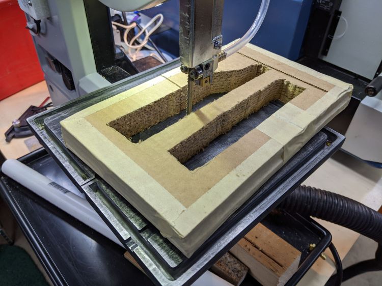
I bandsawed the cutouts from a block with enough layers for some space on the top and bottom:
DM73 – bandsawing cardboard package
After mulling that layout overnight, I made a similar block with the saw cuts on diagonally opposite corners, so pressure on the center of the edges won’t collapse the unsupported sides. A slightly larger meter cutout allowed a wrap of closed-cell foam sheet that likely doesn’t make any difference at all.
With everything in place, the box had just enough space for a pair of plastic sheets to better distribute any top & bottom impacts.
I won’t know how the armor performed for a few weeks, but it’s definitely the best packaging idea I’ve had so far.
Update: After nearly two weeks, the package arrived undamaged and the meter was in fine shape. Whew!