Ed Nisley's Blog: Shop notes, electronics, firmware, machinery, 3D printing, laser cuttery, and curiosities. Contents: 100% human thinking, 0% AI slop.
It’s easy to find the two front screws holding the top in place, although you’ll need either a bendy or offset screwdriver to remove them:
Sears Progressive Vacuum – front case screws
Pull up hard on the cord retraction plunger to remove it, revealing the two rear screws:
Sears Progressive Vacuum – rear case screws
Extract the wires and motor control PCB from their niches:
Sears Progressive Vacuum – motor assembly overview
Prying the latch in the middle of the rear panel (over on the right) releases the motor assembly, which you can then wiggle-n-jiggle upward and out:
Sears Progressive Vacuum – extracting motor assembly
Disconnect the wires, peel off various foam bits, and extract the motor from its carapace. Measure the blower diameter and cut a suitable plywood clamp for the bench vise:
Sears Progressive Vacuum – custom motor clamp
I loves me some good laser cutter action, even when the plywood crate the laser came in doesn’t have much to recommend it:
Sears Progressive Vacuum – failed plywood clamp
I vaguely recall reading the purple tinge comes from the bromine vapor used to dis-insect the wood during manufacturing, before shipping it halfway around the planet.
One area of the commutator looks like it’s in bad shape:
Sears Progressive Vacuum – as-found commutator
Clean the commutator bars in the desperate hope it’s just random crud, even though that seems unlikely, then connect a widowmaker cord to the motor terminals:
Sears Progressive Vacuum – widowmaker line cord
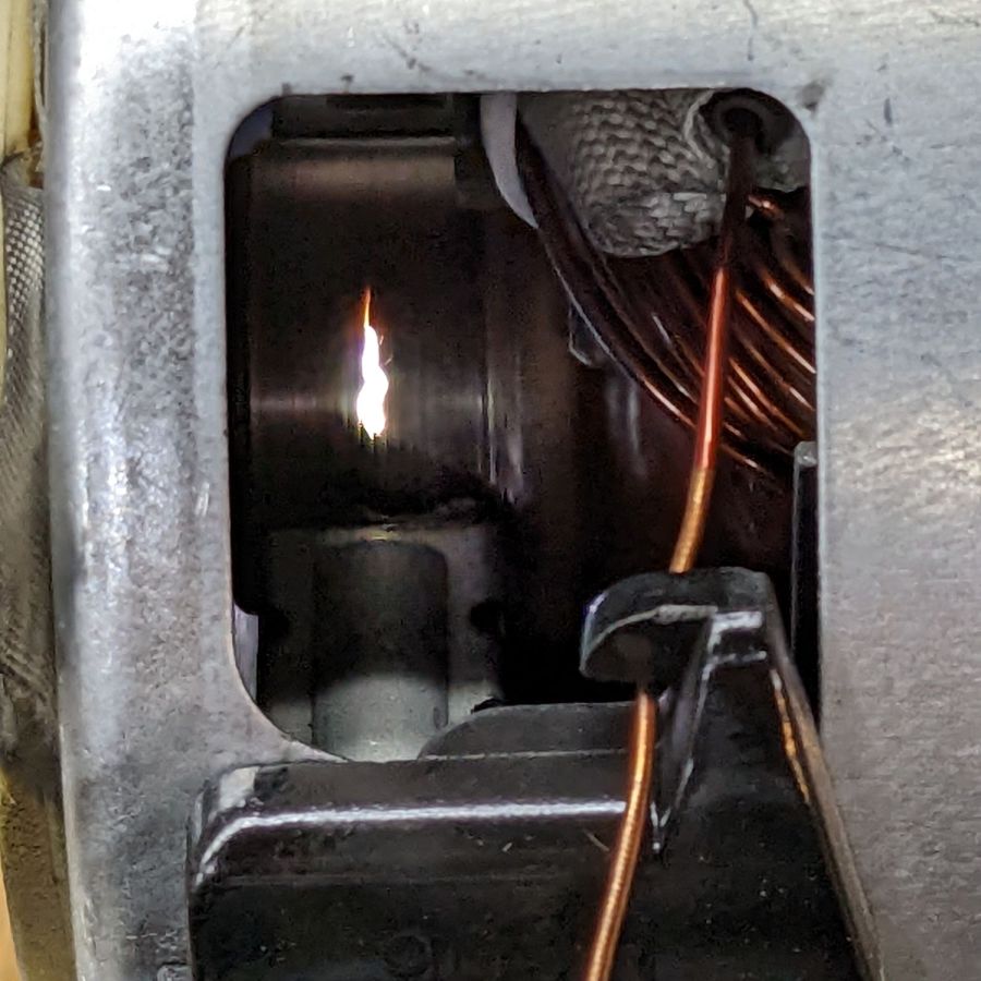
Use a Variac to spin the motor at a (relatively) low speed while watching the brushes and commutator:
Sears Progressive Vacuum – commutator sparking
Now, that is not a nominal outcome.
The cleaned commutator again shows signs of distress:
Sears Progressive Vacuum – scarred commutator
Indeed, measuring the resistance across the line cord terminals shows a shorted winding: 0.0 Ω with the brushes aligned on the bars just antispinward of the scars.
So the motor is definitely, irretrievably dead.
Extracting the brushes shows the arcs have eroded their spinward edges:
Sears Progressive Vacuum – eroded motor brushes
The dark smudge on the windings seems due to internal problems, rather than just the arcs, because the wiring crossing between the commutator and the smudge remains clean:
Sears Progressive Vacuum – charred motor windings
One can buy a used motor assembly on eBay for about $40, with no assurance it doesn’t also have a shorted winding.
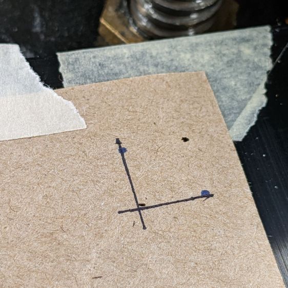
Burn some holes and draw lines 10 mm in from the physical corners, like this:
LB Camera Cal – corner target
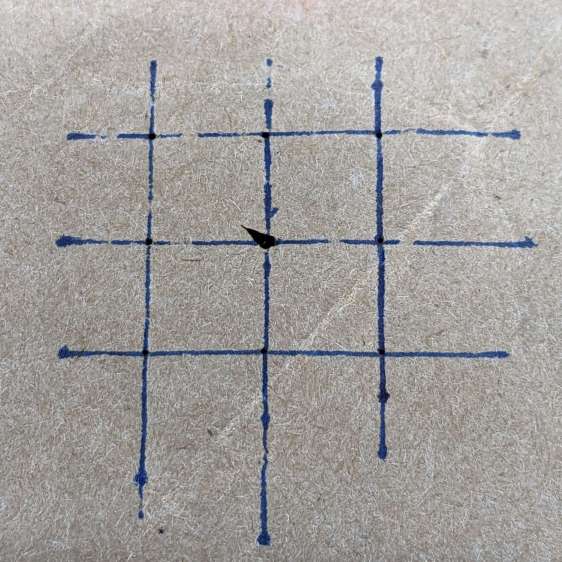
Burn holes and lay in a 10 mm grid at the center point:
LB Camera Cal – center grid
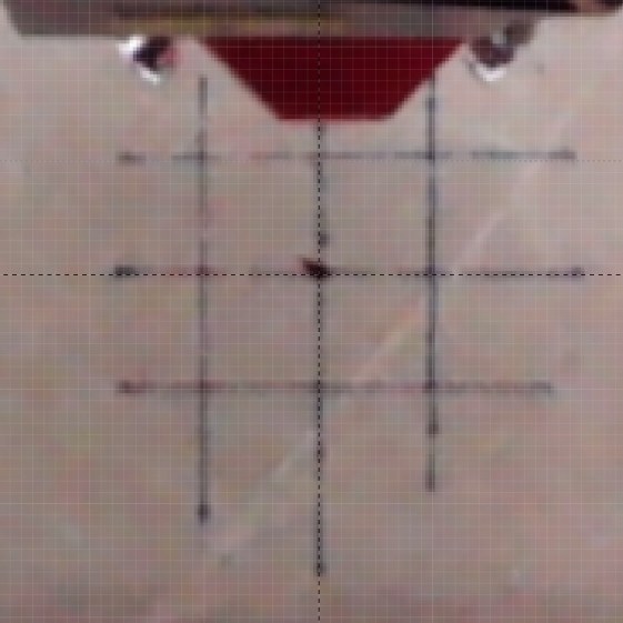
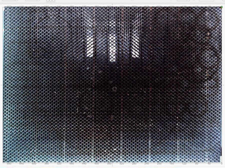
The center grid as seen through the camera:
LB Camera Cal – center grid overlay
That’s after adjusting the X and Y offset to align the center of the imaged grid with the center of the design grid. That’s using the non-faded image to make the target lines more visible.
The corner markers don’t quite line up with the grid, but they’re not off by much (using the faded image to make the grid more visible):
You could, of course, split the difference among all five sites, but I think having the middle of the platform be more accurate than the far corners makes more sense.
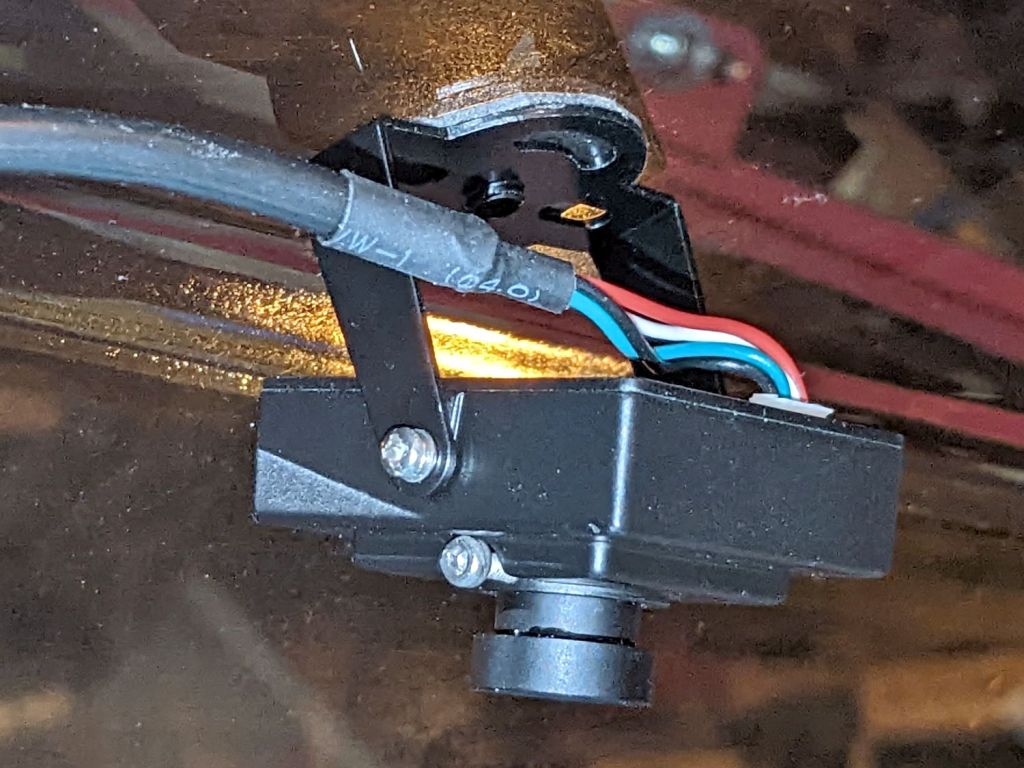
Early on, I stuck a camera to the lid of my OMTech 60 W laser:
OMTech Laser – camera mount
The uncorrected view from the camera (through VLC):
LB Uncorrected Camera View
After calibration and alignment, LightBurn underlays this view of the platform behind the workspace:
LB Corrected Camera View
The correction depends critically on the camera maintaining its position / orientation / focus, which turns out to be a bad assumption for the camera I’ve been using, because the (metal) focus locking screw binds directly on the (metal) lens threads. This works, until vibrations slightly loosen the screw and the lens shifts ever so slightly.
After noticing the focus had shifted again, I tucked a snippet of silicone insulation from some 30 AWG hookup wire into the screw hole to compress against the lens thread, then re-did the entire sequence with some attention to detail.
Pulsing the laser in each corner produced pinholes exactly 700×500 mm apart. One diagonal is 859.0 mm and the other is 861.5 mm, pretty close to the ideal 860.2 mm.
Next, to measure the offsets from some known positions …
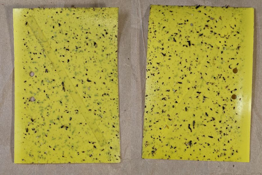
Mary left the sticky card traps in the onion patch until the last onions came out, clustered them around the leeks, and collected them long after the season was over.
I count maybe twenty flies that might be onion maggot flies or cabbage maggot flies.
The cards protected the onion crop, failed miserably for the leeks, and did nothing for the nearby cabbages. Deploying the cards while planting worked very well, refreshing them after a month continued the protection, but the main fly season seems to end shortly thereafter.
All the sticky cards as a slideshow, starting with the three along the border fence:
VCCG Onion Card – fence A – 2022-11
VCCG Onion Card – fence B – 2022-11
VCCG Onion Card – fence C – 2022-11
VCCG Onion Card – plot A – 2022-11
VCCG Onion Card – plot B – 2022-11
VCCG Onion Card – plot C – 2022-11
VCCG Onion Card – plot D – 2022-11
The cards remain sticky to my fingers, but an adroit fly could skate over the debris field and emerge unscathed.
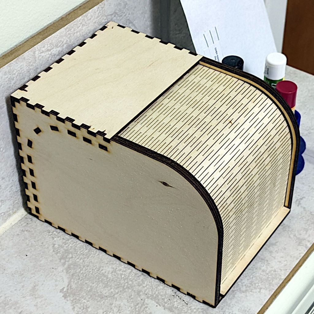
It’s actually the sample Bread Box, sized just about right for a cupcake or two:
Rolltop cupcake box – closed
Even if I have a soft spot for cupcakes, it’s also the right size to corral the batteries we use on the bikes:
Rolltop cupcake box – open
I’d never done anything with flexible plywood sheets, so I started by cutting the door all by itself. Turns out 3 mm plywood flexes wonderfully well, which led to cutting the rest of the box.
The zit on the left side is a knot on the “bad” side of the plywood, visible due to not reversing that piece to put its “good” side downward. I also had to re-cut the curved door guides along the front edge (using the paper support) after they fell through the stock (up on spikes) and got torched during subsequent cuts:
Rolltop cupcake box – cutting guides
The instructions recommend applying wax to the sliding surfaces and that’s a very good idea; although I used cutting wax, paraffin should work. In addition, I filed off the projecting edges of the guide plates around the interior curve, if only to be sure the door couldn’t possibly catch after it was permanently assembled.
I glued it in about five stages to keep everything aligned, starting with the right rear corner stabilized by the bench block and eventually coaxing the left side over all those fingers.
It did, however, dry the tubing and the construction was Pretty Close™ to being the proper size.
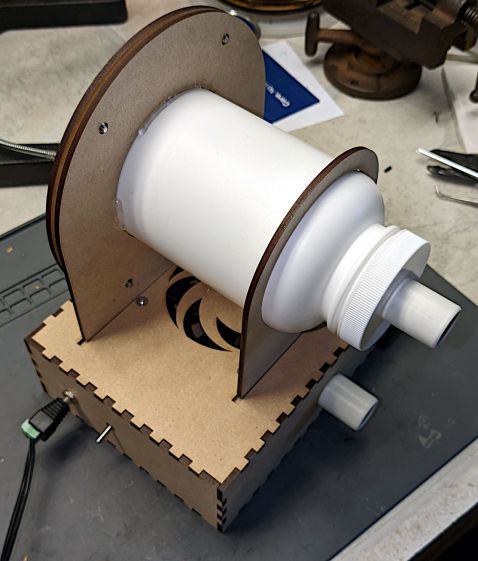
Making the stand from acrylic sheet eliminates the MDF stench:
CPAP Dryer filter – acrylic stand – fitting end
Incoming air passes through a dome-style N95 mask:
CPAP Dryer filter – acrylic stand – filter end
The mask sets the overall size of the stand:
CPAP Dryer – Filter holder – LB layout
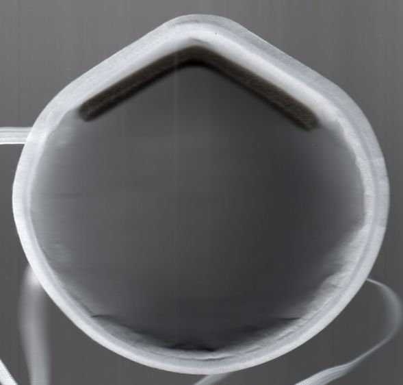
Given that we’re not talking Level 4 Biohazard, any filter would work equally well. A dome mask has a nicely defined and self-supporting shape with a flange around the edge.
The flange provides a convenient way to build the clamp ring, starting with a scan from the face side:
Demetech Dome Mask – interior scan
Tracing the flange outline using GIMP’s Scissor Select tool and doing a little cleanup in Quick Mask mode produced a selection suitable for becoming a binary mask of the N95 mask:
Demetech Dome Mask – perimeter mask
Ex post facto, I realized the mask has a sufficiently regular outline to fit a much simpler Beziér spline:
CPAP Dryer – Filter holder – LB splines
That began in LightBurn as a circle fitting the lower part of the mask, converted to a path, then tweaked with the Node Editor to fit the top of the nose and add two nodes to pull the path inward on either side. In the unlikely event I make another bottle stand, the cut will be irrelevantly smoother.
The hole in the clamp comes from insetting that path by the flange width of 4 mm, whereupon the N95 mask pretty much self-centers in the hole:
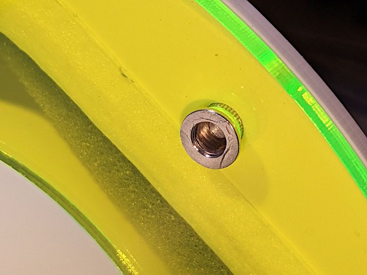
They’re shortened by 1 mm (from the original length shown in the upper right) to fit 1 mm of mask sandwiched inside a pair of 3 mm acrylic sheets:
CPAP Dryer filter – Rivnut installed
The glowy edge-lit acrylic sheet has 4.8 mm holes for a snug push fit and the white clamp ring has 5.1 mm holes for a loose alignment fit. I drilled out the laser-cut holes for nice smooth sides.
I picked a bottle large enough to also hold the mask’s elbow, so that it would dry in the same stream of clean air. So far, the elbows dry well enough on their own, but the bottle remains a convenient size for fitting the mask on its end.
On the other end of the bottle, the lid gets a hose fitting turned from PVC pipe:
CPAP Dryer – filter hose fitting glue rings
The Official ResMed fittings on the masks and the AirSense 11 machine are about 20 mm long and just over 22 mm OD with a slight taper. The unheated hose has silicone rubber ends fitting very snugly around those cylinders, so I made the pipe fittings 25 mm long and 21 mm OD to ensure a low-effort, but still secure, fit.
The grooves cut into the fitting anchor a generous hot-melt glue blob sealing it to the lid:
CPAP Dryer – filter hose fitting inside
Yes, the foam disk and the hole through the lid were both laser-cut. Making perfect circles in thin organic material with zero drama is wonderful.
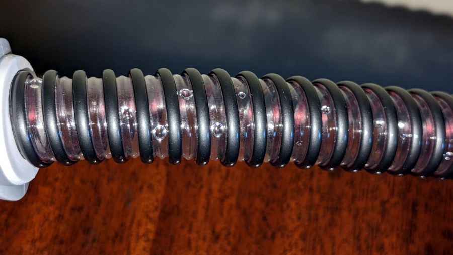
The downstream / mask end of the heated ClimateLine hose (left) is physically identical to the unheated hose ends, but the machine / upstream end (right) sports an electrical connector for the spiral heating element and the thermistor (in the white stud protruding into the mask end lumen):
ResMed ClimateLine heated hose ends
Yes, that does look a lot like a naked USB connector, as does the main power connection on the machine, and you can actually slide a Type A USB connector around it. The ResMed manual pointedly notes:
•Do not insert any USB cable into the AirSense 11 device or attempt to plug the AC adaptor into a USB device. This may cause damage to the AirSense 11 device or USB device. •The electrical connector end of the heated air tubing is only compatible with the air outlet at the device end and should not be fitted to the mask.
The four ribs inside the upstream end slide over a 23.5 mm cylinder, which is enough larger than the 22 mm cylinder on the machine to wiggle the not-USB connector into place. Without a connector to worry about, I turned a sleeve adapting the smaller fitting to those ribs:
CPAP Dryer filter – heated hose bushing
It’s 27 mm long to keep the lip of the silicone seal away from the setscrew, 23.5 mm OD to exactly fit between the ribs, and a 21.5 mm ID slip fit over the bottle snout.
The tiny M3 setscrew lives in a hole tapped into the inner tube, because the sleeve is only 1 mm thick:
CPAP Dryer filter – acrylic stand – bushing center drill
The setscrew turns outward into a clearance hole drilled in the sleeve to lock it in place.
The outer PVC pipe in the vise is a simple cylinder fixture bored to match the sleeve, so I could grab it in the lathe chuck / vise without distortion. Just the force from a normal grip squishes the fixture enough to keep the sleeve from turning / moving / getting annoyed.
Improving the MDF fan box awaits a few parts, but, being downstream, isn’t on the critical path for drying hoses. The only trick is keeping the bottle inlet upstream of the fan exhaust.
For all the usual reasons, we’re now confronted with the need to dry a freshly washed CPAP hose:
CPAP Dryer – water droplets in hose
Those droplets might not seem like much, but I am reliably informed they produce over-humid air and sprinkle when they migrate into the mask during the night.
Commercial drying machines are available, but seem grossly overqualified and require proprietary foam filters. I wondered if simply pulling air through the hose for a few hours would work:
CPAP Dryer – dried hose
Why, yes, it does.
That test took two hours and another with a different hose required about five, but simply “hanging the hose up to dry” consistently produced poor results after three days, so we count a few hours as a win.
Stipulated: MDF is absolutely the wrong material for an air-handling project, because laser-cut MDF stinketh unto high heaven. This was the first pass using cheap material to see how well, if at all, the idea worked.
The CPAP hose goes between the fittings on the bottle and box, with air entering the bottle through a hole drilled in what was its bottom:
CPAP Dryer – filter bottle cutout
An air filter seemed like a Good Idea™, if only to keep ordinary room fuzz out of the bottle and hose. In this Third Pandemic Year, I could simply pull a least-favorite N95 mask from the stockpile and fit a clamp ring around it:
CPAP Dryer – filter clamp installed
The motivation for pulling air through the tube, rather than pushing it, came when I realized I could build a much cleaner intake structure by starting with an ordinary HDPE bottle than I could possibly assemble from random parts.
So the fan in the box pulls air through the fitting on the side of the box and blows it out the swirl on top:
CPAP Dryer – fan box
The box contains a coaxial power jack, the switch, and an 80 mm fan extricated from the Box o’ MostlyFans. I briefly considered an LED, but it’s obvious when the fan runs. The box and swirl cutting patterns come from the invaluable festi.info.
The two slots give the bottle somewhere to stand while idle. In use, the hose is sufficiently unwieldy to require standing the bottle wherever it wants to be, rather than insisting on putting it anywhere in particular.