The Smell of Molten Projects in the Morning

Ed Nisley's Blog: Shop notes, electronics, firmware, machinery, 3D printing, laser cuttery, and curiosities. Contents: 100% human thinking, 0% AI slop.

Category: Machine Shop

Mechanical widgetry

  • Prusa MK4 + MMU3 Test Piece

    Prusa MK4 + MMU3 Test Piece

    The slanted layers mean this simple block requires something like 180 filament changes while verifying the Prusa MK4 + MMU3 / filament buffer setup:

    Prusa MK4 MMU test piece - finished
    Prusa MK4 MMU test piece – finished

    Because of all the color changes, the Wipe Tower holding the extruder waste is much much larger than the block:

    Prusa MK4 MMU test piece - on platform
    Prusa MK4 MMU test piece – on platform

    The first attempt taught me, once again, the value of cleanliness:

    Prusa MK4 MMU test piece - birds nest as found
    Prusa MK4 MMU test piece – birds nest as found

    The extruder head required tedious cleaning:

    Prusa MK4 MMU test piece - extruder tangle
    Prusa MK4 MMU test piece – extruder tangle

    Scrubbing the steel plate with dish detergent and wiping it with isopropyl alcohol improved the outcome, but one corner of the Wipe Tower still lifted:

    Prusa MK4 MMU test piece - wipe tower corner lifting
    Prusa MK4 MMU test piece – wipe tower corner lifting

    All’s well that ends well, but perhaps glue stick / hair spray under future Wipe Towers will ensure they don’t wander off.

  • Cutting Board Shim

    Cutting Board Shim

    The kitchen counter has only two useful places for the cutting board and the spot Mary favors puts a distinct swale under one corner. A bit of measuring and solid modeling produced a simple shim to make the answer come out right:

    Cutting Board shim - solid model
    Cutting Board shim – solid model

    The basic shape is union() of a trio of hull() operations forming the three sides, with the text label as a separate object to verify I understood how to build a multi-material object.

    Export it as a 3mf file, open it in PrusaSlicer, slice, print:

    Cutting Board shim - label
    Cutting Board shim – label

    Putting the label on the bottom surface takes advantage of the nubbly finish on the Textured Steel Sheet to make it look like it just grew in there.

    The label is just barely visible from the top, despite extending only 1/4 of the way through the 1.6 mm bottom slab:

    Cutting Board shim - top
    Cutting Board shim – top

    So white PETG needs more than 1.2 mm of thickness to hid a black feature. Today I Learned, etc.

    Multi-material printing produces a Wipe Tower to hold all the extruded junk during color changes:

    Cutting Board shim - wipe tower
    Cutting Board shim – wipe tower

    The curl under the nozzle comes from the final ramming used to shape the end of the filament into a point for reliable material / color changing.

    Although a shim is something of a nuisance, it works perfectly:

    Cutting Board shim - in use
    Cutting Board shim – in use

    Much easier than installing an L-shaped Corian slab with a sink cutout!

    The faded engraving dates back to the early days of the laser

    The OpenSCAD source code as a GitHub Gist:

    // Cutting Board alignment shim
    // Ed Nisley KE4ZNU – 2024-08-20
    //—–
    // Dimensions
    ShimThick = 1.6; // thickness of shim under board
    /* [Hidden] */
    ShimOA = [25.0,25.0,15.0]; // overall size of shim
    WallThick = 4.0;
    ShimRadius = WallThick/2;
    LabelThick = ShimThick/4;
    NumSides = 3*4;
    //—–
    // Build it
    union() {
    hull()
    for (i=[0,1])
    translate([i*(ShimOA.x – ShimRadius),0,0])
    cylinder(r=ShimRadius,h=ShimOA.z,$fn=NumSides);
    hull()
    for (j=[0,1])
    translate([0,j*(ShimOA.y – ShimRadius),0])
    cylinder(r=ShimRadius,h=ShimOA.z,$fn=NumSides);
    hull() {
    for (i=[0,1])
    translate([i*(ShimOA.x – ShimRadius),0,0])
    cylinder(r=ShimRadius,h=ShimThick,$fn=NumSides);
    translate([0,1*(ShimOA.y – ShimRadius),0])
    cylinder(r=ShimRadius,h=ShimThick,$fn=NumSides);
    }
    }
    color("Black")
    translate([ShimOA.x/3,ShimOA.y/3,LabelThick])
    rotate([180,0,90 + 45])
    linear_extrude(height=LabelThick,convexity=20)
    text(text=str(ShimThick),size=6,spacing=1.00,
    font="Arial:style:Bold",halign="center",valign="center");
  • Under-cabinet LED Light Brick Mounts

    Under-cabinet LED Light Brick Mounts

    Descending directly from the holders for the MPCNC power brick, slightly smaller brackets for the power bricks attached to the under-cabinet LED strip light in the kitchen:

    Kitchen Under-cabinet light power brick mounts - slicer view
    Kitchen Under-cabinet light power brick mounts – slicer view

    Made from black PETG (because they’re in the kitchen) they fit fine:

    Under-cabinet light - brick B
    Under-cabinet light – brick B

    Although the elegance depends on which way the brick points:

    Under-cabinet light - brick A
    Under-cabinet light – brick A

    They have the distinction of being the first “real” objects from the Prusa MK4. All my hard-won knowledge of forcing solid models into reality through a 3D printer is obsolete: the default slicer settings on a new printer work perfectly, with no fiddling required.

    The OpenSCAD source code as a GitHub Gist:

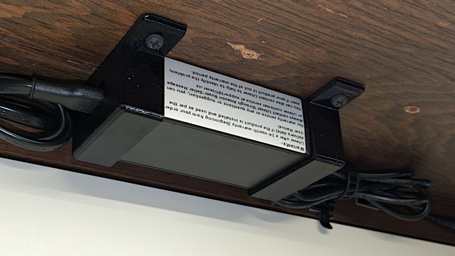
    // Power Supply Brick brackets
    // Ed Nisley KE4ZNU 2024-08-19
    Layout = "Show"; // [Show,Build]
    //– Extrusion parameters
    /* [Hidden] */
    ThreadThick = 0.20;
    ThreadWidth = 0.45;
    HoleWindage = 0.3; // enlarge hole dia by this amount
    function IntegerMultiple(Size,Unit) = Unit * ceil(Size / Unit);
    Protrusion = 0.1; // make holes look good and joints intersect properly
    //– Useful sizes
    ID = 0;
    OD = 1;
    LENGTH = 2;
    //– Bracket Dimensions
    Brick = [115.0,51.0,32.0]; // overall size, add details in module
    Socket = [20.0,10.0]; // binocular power socket
    Cable = [5.0,12.0]; // DC output cable ID=wire OD=strain relief
    //Socket = [30.0,24.0]; // IEC power socket
    //Cable = [6.0,15.0]; // DC output cable ID=wire OD=strain relief
    WallThick = 3.0; // default wall thickness
    BaseThick = 4.0;
    Screw = [5.1,10.0,3.0]; // screw size, more-or-less 10-32, OD & LENGTH for head
    NumSides = 3*4;
    //———————-
    // Useful routines
    module PolyCyl(Dia,Height,ForceSides=0) { // based on nophead's polyholes
    Sides = (ForceSides != 0) ? ForceSides : (ceil(Dia) + 2);
    FixDia = Dia / cos(180/Sides);
    cylinder(r=(FixDia + HoleWindage)/2,
    h=Height,
    $fn=Sides);
    }
    //———————-
    // Models
    module BrickMount(End="Both") {
    difference() {
    union() {
    hull() // main block
    for (i=[-1,1], j=[-1,1], k=[0,1])
    translate([i*(Brick.x/2 + WallThick – WallThick),
    j*(Brick.y/2 + WallThick – WallThick),
    k*(Brick.z + WallThick – WallThick)])
    sphere(r=WallThick,$fn=NumSides);
    hull() // screw flanges
    for (i=[-1,1], j=[-1,1])
    translate([i*(Brick.x/2 + WallThick – BaseThick),
    j*(Brick.y/2 + WallThick + 2*Screw[OD] – BaseThick),
    0])
    sphere(r=BaseThick,$fn=NumSides);
    }
    for (i=[-1,1], j=[-1,1]) // remove screw holes
    translate([i*(Brick.x/2 + WallThick – Screw[OD]),
    j*(Brick.y/2 + WallThick + Screw[OD]),
    -Protrusion])
    rotate(180/6)
    PolyCyl(Screw[ID],2*WallThick,6);
    translate([0,0,Brick.z/2]) // remove center part to leave ends
    cube([(Brick.x + 2*WallThick – 4*Screw[OD]),2*Brick.y,2*Brick.z],center=true);
    if (End == "Socket")
    translate([Brick.x/2,0,Brick.z/2]) // remove cable end to leave socket
    cube([(Brick.x + 2*WallThick – 4*Screw[OD]),2*Brick.y,2*Brick.z],center=true);
    if (End == "Cable")
    translate([-Brick.x/2,0,Brick.z/2]) // remove socket end to leave cable
    cube([(Brick.x + 2*WallThick – 4*Screw[OD]),2*Brick.y,2*Brick.z],center=true);
    translate([0,0,Brick.z/2 – Protrusion/2]) // remove power supply brick from interior
    cube(Brick + [0,0,Protrusion],center=true);
    translate([0,0,-Brick.z]) // remove below XY plane
    cube(2*Brick,center=true);
    translate([0,0,Brick.z/2]) // remove AC socket
    rotate([0,-90,0])
    rotate(90)
    linear_extrude(height=Brick.x,convexity=2)
    square(Socket,center=true);
    translate([0,0,Brick.z/2]) // remove DC cable
    rotate([0,90,0])
    rotate(180/8)
    PolyCyl(Cable[OD],Brick.x,8);
    translate([Brick.x/2,0,Brick.z/4 – Protrusion/2]) // … and wire slot
    cube([Brick.x,Cable[ID],Brick.z/2 + Protrusion],center=true);
    }
    }
    //———————-
    // Build it
    if (Layout == "Show")
    BrickMount("Both");
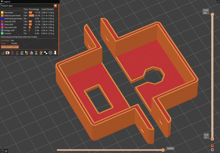
    if (Layout == "Build") {
    translate([5,0,Brick.x/2 + WallThick])
    rotate([0,90,0])
    BrickMount("Cable");
    translate([-5,0,Brick.x/2 + WallThick])
    rotate([0,-90,0])
    BrickMount("Socket");
    }
  • Water Shutoff Valves: Autopsy

    Water Shutoff Valves: Autopsy

    After a bit more than half a century, the rubber washer in the cold water shutoff valve for the kitchen sink had fossilized:

    Sink shutoff - cold washer
    Sink shutoff – cold washer

    The hot water washer was in much worse condition:

    Sink shutoff - hot washer
    Sink shutoff – hot washer

    The shutoff valve for the hose bib in the front of the house, mounted knob-downward, has been dripping quietly for many many years before I replaced it:

    Hose valve shutoff - knob corrosion
    Hose valve shutoff – knob corrosion

    I’d turned the valve off to no avail, so this was no surprise:

    Hose valve shutoff - washer
    Hose valve shutoff – washer

    While it is theoretically possible to replace those washers, even the professionals know better than to disturb a sleeping valve:

    Dishwasher valve doubling
    Dishwasher valve doubling

    The tandem valve was likely installed half a decade ago, along with the dishwasher it services. Perhaps the washer inside remains soft.

  • GripStic Shortening

    GripStic Shortening

    We’ve been using GripStic Bag Sealers on bags around the kitchen with good results, but the “XLarge” pink sticks far exceed the largest bags we have. While not the worst problem I’ve encountered in the last year, I can fix that:

    Gripstic - shortened assortment
    Gripstic – shortened assortment

    An elaborate latch aligns the yellow rod along the axis of the outer shell:

    Gripstic - rod end feature
    Gripstic – rod end feature

    I shortened the stick with Tiny Bandsaw™, cleaned up the ends, squirted hot melt glue into the shell, set it on a bench block, rammed the yellow rod into the glue, and paused for contemplation:

    Gripstic - shortened glue
    Gripstic – shortened glue

    Trim off the blob and it’s all good.

    The WordPress AI suggests “Additionally, including tips for handling the Tiny Bandsaw™ and hot melt glue would be beneficial.” So, as always, use your tools carefully, OK?

    Adding the preceding paragraph changed the AI suggestion to “To further improve the content, consider adding tips for handling the Tiny Bandsaw™ and hot melt glue for the readers’ benefit. Always prioritize safety when using tools.” I recommend not juggling Tiny Bandsaw™ and a hot melt glue gun, particularly went they’re running.

  • Prusa MK4 Y Motor Shim

    Prusa MK4 Y Motor Shim

    Having been viciously nerd-sniped by The Great Dragorn of Kismet, I’m in the process of building a Prusa MK4 3D printer with an MMU3. This has been a generally pleasant experience, although I am beginning to loathe Genuine Haribo Goldbären.

    Anyhow, the Y axis motor position puts the belt too close to one side of the pulley, with no further adjustment possible:

    Prusa MK4 Y axis motor mount - as-built
    Prusa MK4 Y axis motor mount – as-built

    The stepper motor stator laminations are the striped gray area on the far left, the 3D printed motor mount is the striped black area on the right, and the belt pulley is snugged up against the motor as far as it can go on the shaft.

    Pushing the motor a little more to the left requires a shim:

    Prusa MK4 Y axis motor mount - shim
    Prusa MK4 Y axis motor mount – shim

    Rather than fiddle with scanning the motor mount, I imported its STL model from the Prusa MK4 files:

    Prusa MK4 Y Axis Motor mount - solid model
    Prusa MK4 Y Axis Motor mount – solid model

    Importing the STL into OpenSCAD and converting the motor face into an SVG file is basically a one-liner:

    projection(cut=true)
    translate([0,0,-5.0])
    import("/mnt/bulkdata/Project Files/Prusa Mk4/Calibration/y_motor_holder_R3.stl");
    

    Import the SVG into LightBurn, round the corners a little, set it up for 1.5 mm Trocraft Eco, Fire. The. Laser. and it fits perfectly and stands out nicely:

    Prusa MK4 Y axis motor mount - shimmed
    Prusa MK4 Y axis motor mount – shimmed

    Having the right tools for a job makes it easy …

  • Home Depot Glacier Bay Kitchen Faucet: Round 2

    Home Depot Glacier Bay Kitchen Faucet: Round 2

    The kitchen faucet worked its way loose again. Attempting to shut off the water revealed a pair of leaky valves under the sink, so I shut off the house water in the basement, cut the valve pipes below the solder drips, and installed a pair of push-connect shutoffs:

    Kitchen faucet shutoff valve - push connection
    Kitchen faucet shutoff valve – push connection

    I loves me some good push-connect fitting action, which is new news to me. Back in the Bad Old Days™, I’d be under the sink with a propane torch, trying to solder a pair of wet pipes and failing miserably.

    With that out of the way and the faucet dismantled for the first time (by my hands, anyway), the threads holding the base to the spout column may have been damaged during factory assembly:

    HD Glacier Bay kitchen faucet - damaged threads
    HD Glacier Bay kitchen faucet – damaged threads

    I thought the gunk was thread lock compound, but it’s shredded plastic from the base fitting threads. The corresponding female threads inside the spout column are undamaged, so I think somebody tried screwing it together with the threads misaligned, backed off, then muscled it together.

    It’s worth noting there are no keys or stops fixing the correct orientation of any of these parts. In particular, the trim ring bearing the small Front label (facing you in the picture) has no fixed orientation: whoever assembles the faucet in the factory must position it correctly on the fly as the base screws into the column and jams tight.

    So I cleaned up the damaged threads as best I could, flipped the threaded brass tube end-for-end to put the cleanest part into the base, and reassembled everything with careful attention to starting the threads correctly:

    HD Glacier Bay kitchen faucet - flipped brass tube
    HD Glacier Bay kitchen faucet – flipped brass tube

    Tightening the base fitting into the column is much easier with everything on the kitchen counter, although centering the label on the molded opening required several tries.

    Protip: a pair of grippy gloves and rubber sheets help a lot.

    I want to find out how secure the original design, properly tightened and aligned, will be, so I did not apply any threadlocker.