Ed Nisley's Blog: Shop notes, electronics, firmware, machinery, 3D printing, laser cuttery, and curiosities. Contents: 100% human thinking, 0% AI slop.
We deployed low-effort vole trap boxes a few weeks ago, only to discover no voles checked in, most likely due to wintertime gardens consisting of bare earth. I had weighted the boxes with convenient rocks that pretty much crushed them flat during rainstorms.
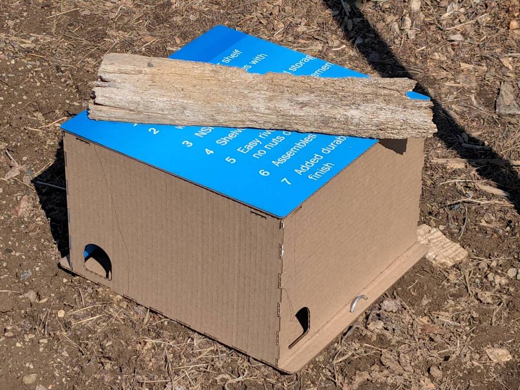
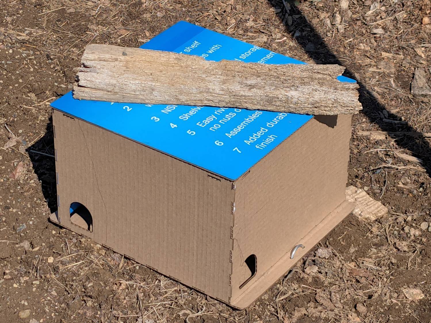
So I converted a few dozen square feet of cardboard into better-looking boxes and transferred the traps:
Vole Finger Box – large
That one has a rat trap inside.
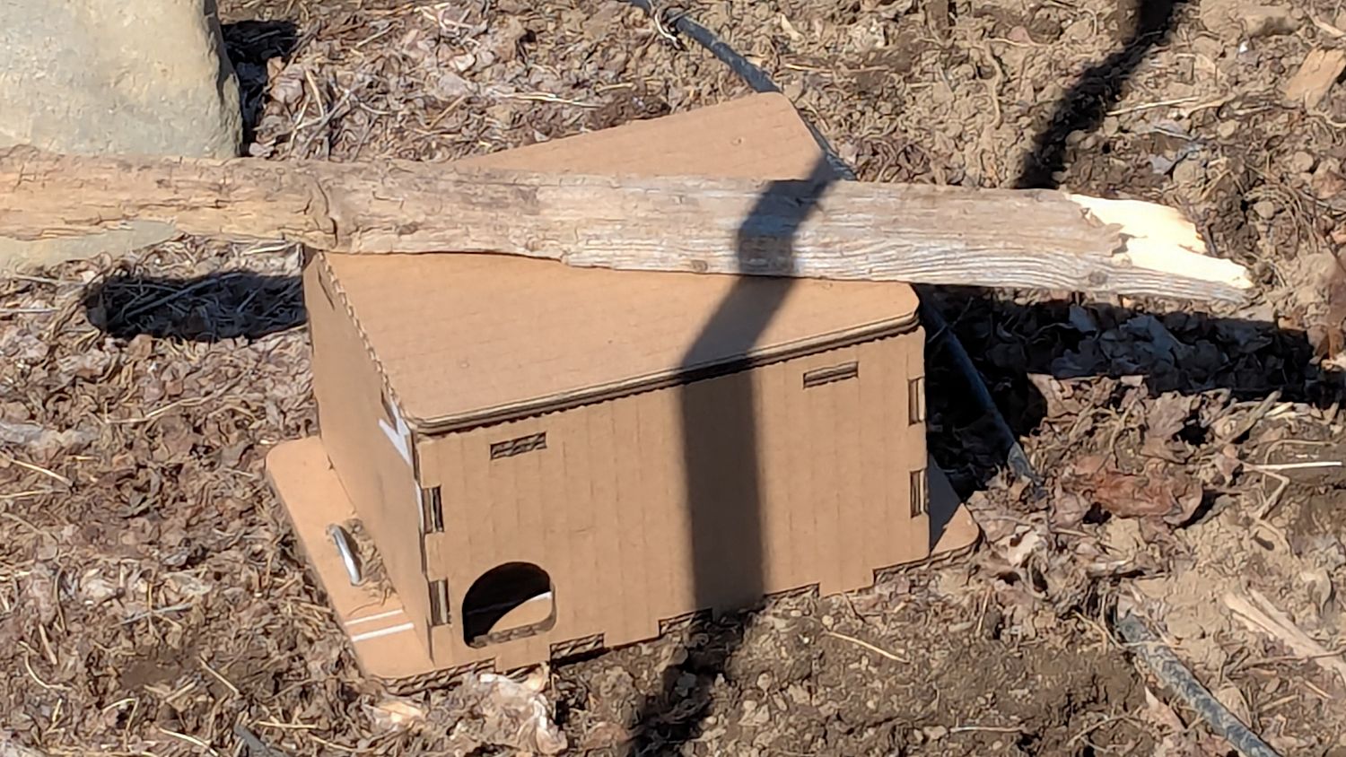
Smaller boxes hold mouse traps:
Vole Finger Box – small
Two pairs of 4 mm holes on the bottom flanges fit some spare irrigation pipe holddowns to, yes, hold them down, with those rotten planks keeping their lids in place.
They’re lightly customized “Electronics Boxes” held together by hot-melt glue. The jawbreaker URLs will get you started:
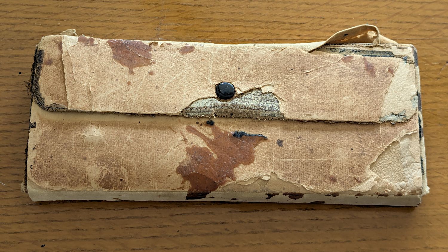
Our Young Engineer recently rebuilt the cover of a “vintage” drawing kit, with fabric pockets for protractors & scales and real leather hinges, thereby raising a long-procrastinated project to the top of my to-do list:
TEC Drawing Set – top old
I know my father used it when he took drafting after high school in 1929. His penmanship and drawing ability were up to par well before that.
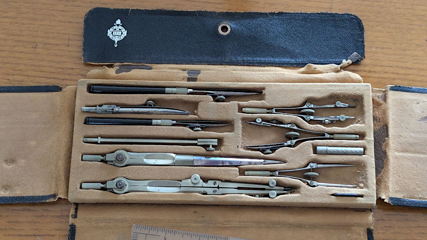
The inside sports a TEC logo:
TEC Drawing Set – open old
Some searching revealed it’s a No. 718 Drafting Set from the Technical Supply Company of Scranton and appeared in their 1913 catalog:
TEC Brand Catalog p68
The printing on the inside of the flap differs, but the logo has TEC in the middle.
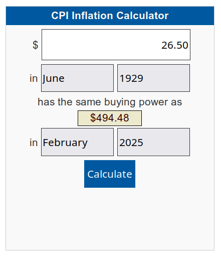
My father did not attend college and, in the teeth of The Great Depression, $26.50 was certainly too spendy for his family:
CPI Calculator – 1929 to 2025
When the catalog was printed in 1913, No. 718 cost the equivalent of $862.82. Nowadays, similar sets once again cost about twenty bucks on eBay, which tells you something about economics.
In retrospect, I should have used two leather snaps, but three would be excessive.
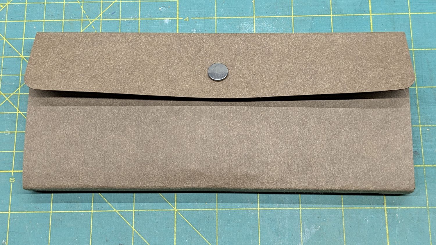
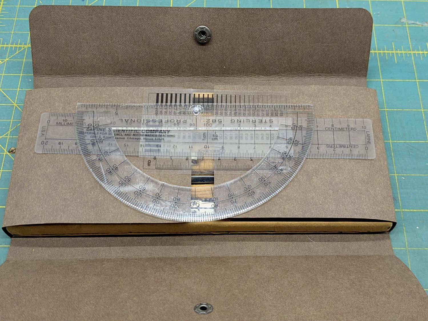
I folded the Kraft-Tex flat across a steel scale to make the first folds around the base, then finger-crimped folds at the top of the base with subsequent crisping around the scale:
TEC Drawing Set – open new
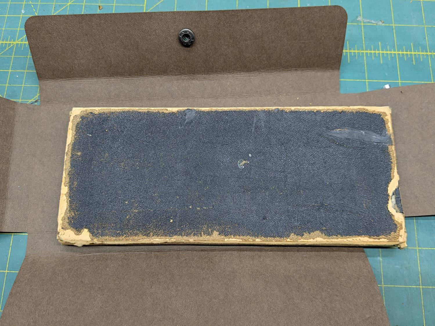
The underside of the original case seemed stable:
TEC Drawing Set – case bottom
This may be sacrilege, but I saw no point in peeling the bottom just to cover it up,so I stuck the Kraft-Tex in place with a rectangle of adhesive sheet.
It doesn’t look the same, but it still gives me a warm feeling.
It still has the tiny wrench needed to adjust all its screws:
TEC Drawing Set – wrench
It’s on 0.1 inch graph paper and is 40 mil = 1 mm thick, should you want to make your own. The blades taper down to essentially a knife edge, which is why it’s made from hard blue steel.
I remember being fascinated by that little pig when I was a pup.
Putting some scraps to good use, I stuck a cushion in the anvil for the next time I punch down a leather snap:
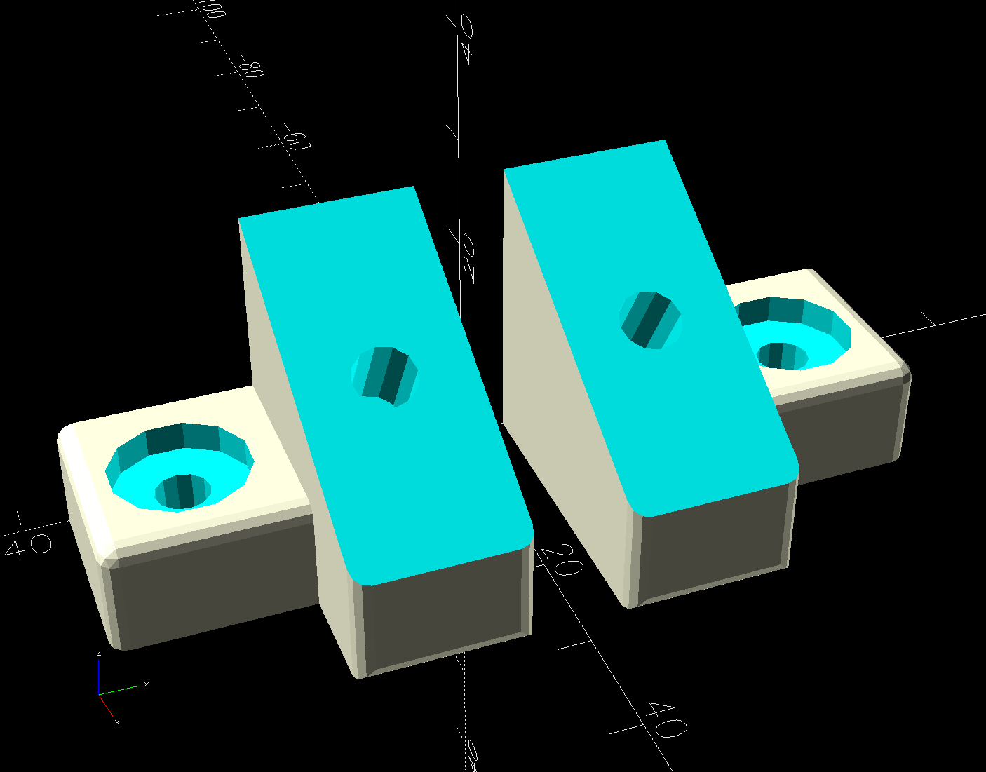
The object of the game being to tilt the LED strip lights at (maybe) 30° to put more light higher on the wall and further out on the ceiling, with the overriding constraint of no visible holes. Given their eventual home atop the window moulding along the front wall of the Living Sewing Room, these seemed adequate:
LED Bar Lamp Mount – solid model
The hole on the angled part fits an M4 brass insert and the recessed holes capture the washer-like head of a sharp-point lath screw.
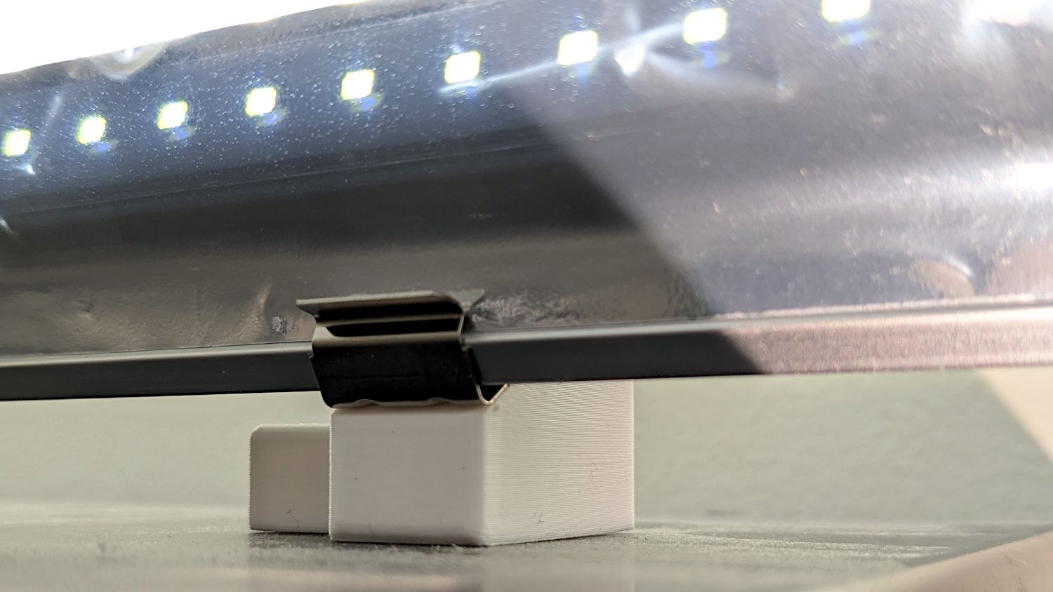
Two pairs applied to the lights sitting atop the Fabric Cabinets served to verify the fit:
LED strip light – moulding mount – on cabinet
They’re held firmly by the aluminum extrusion and don’t need a bigger footprint to remain stable.
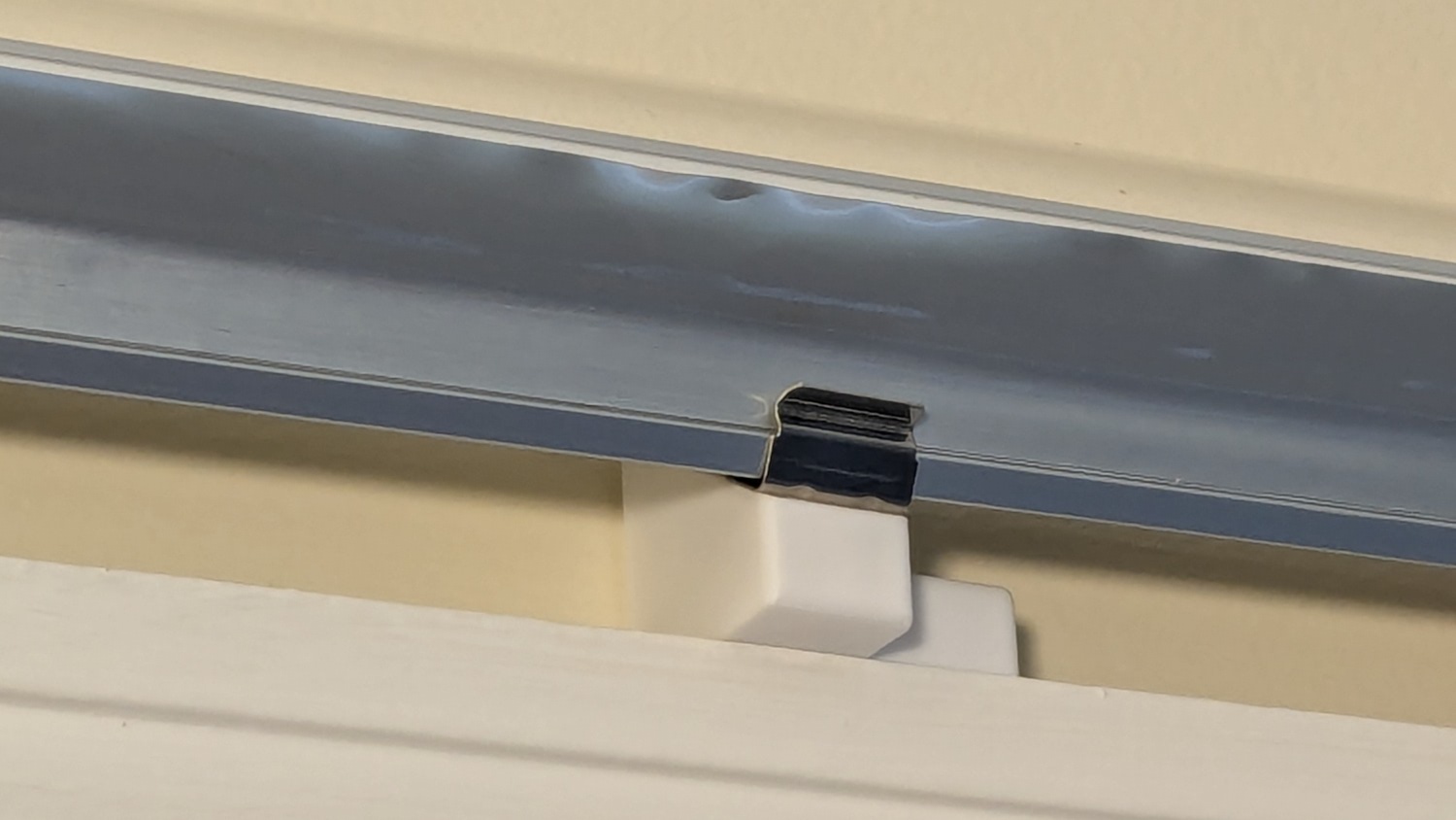
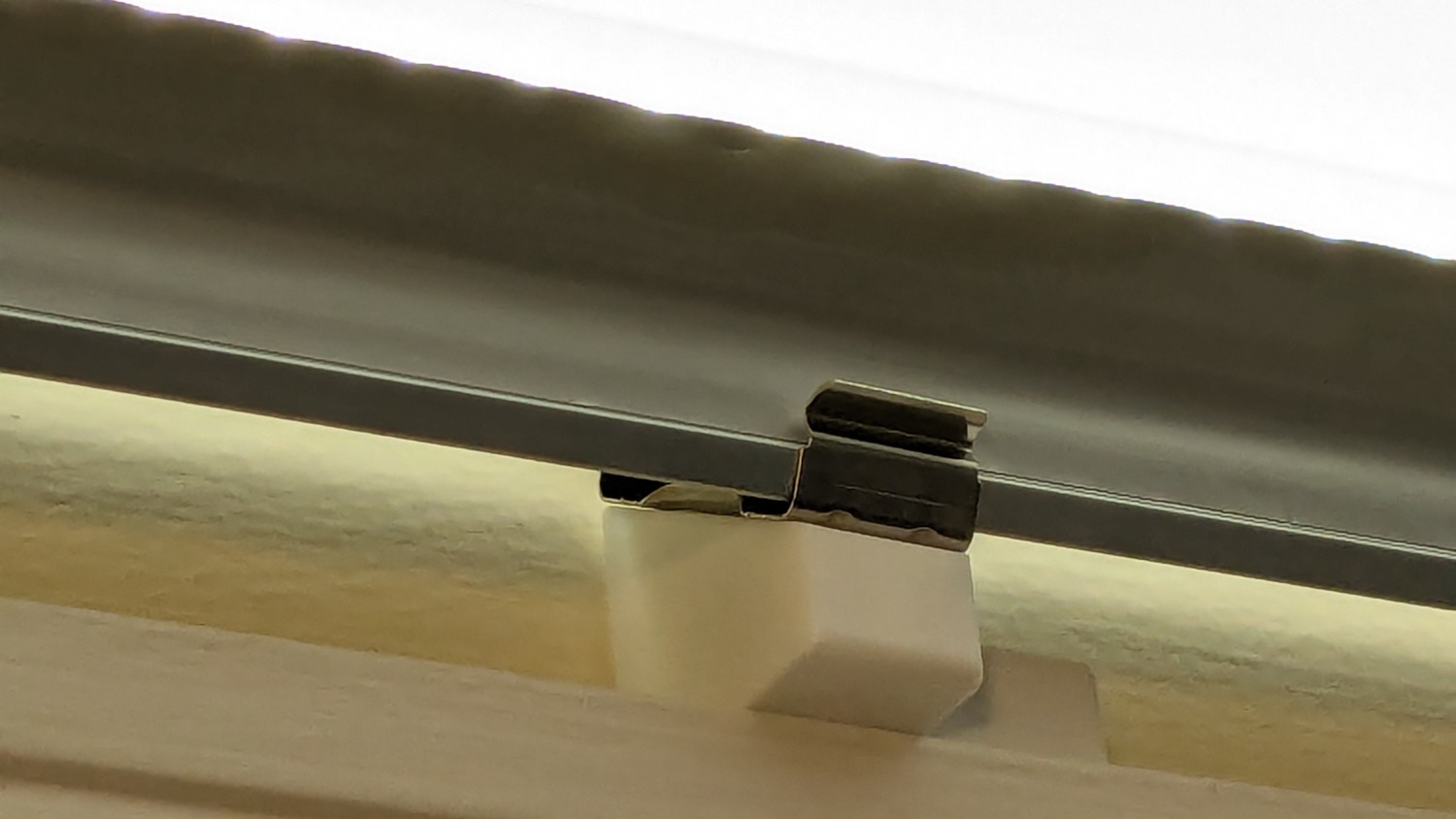
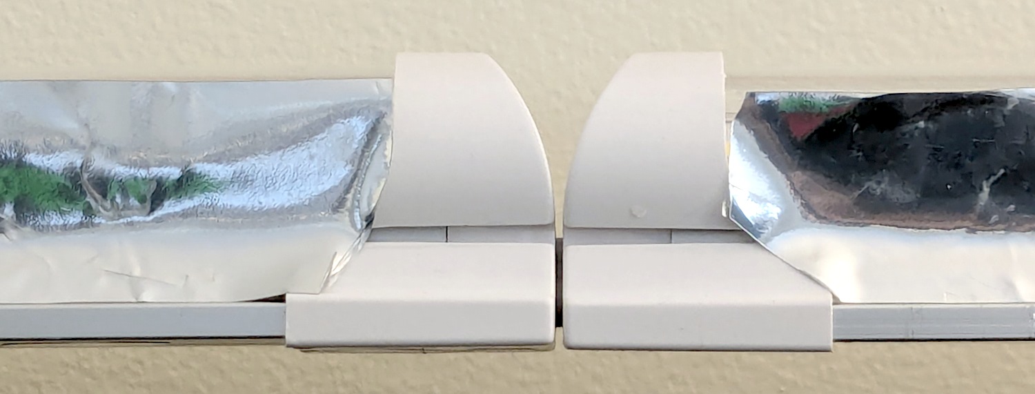
So I made another six, stuck on ⅞ inch strips of aluminized Mylar (cut from a bag in much better condition), and drilled holes where they can’t be seen:
LED strip light – moulding mount – installed
It’s almost too bright in there with 3 × 40 W of LED lights washing the wall and ceiling:
LED strip light – moulding mount – lit
I don’t like the cold 6000 K color temperature, but Mary doesn’t mind it. They fill the Sewing Table with shadowless / glareless light, although that kind of light makes the place look like a store.
I think moving the strip lower and away from the wall could hide the entire mount from view.
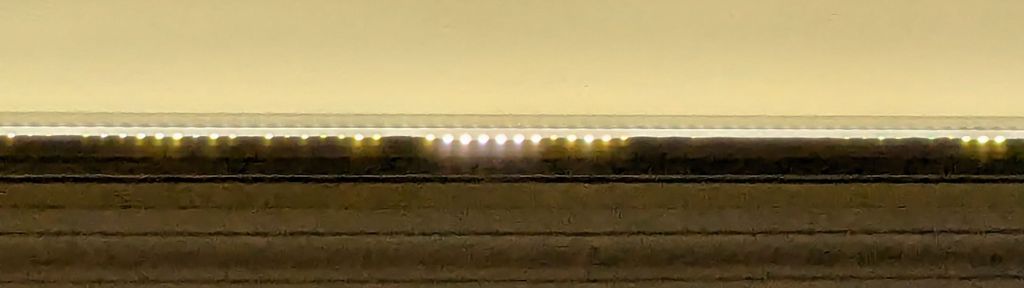
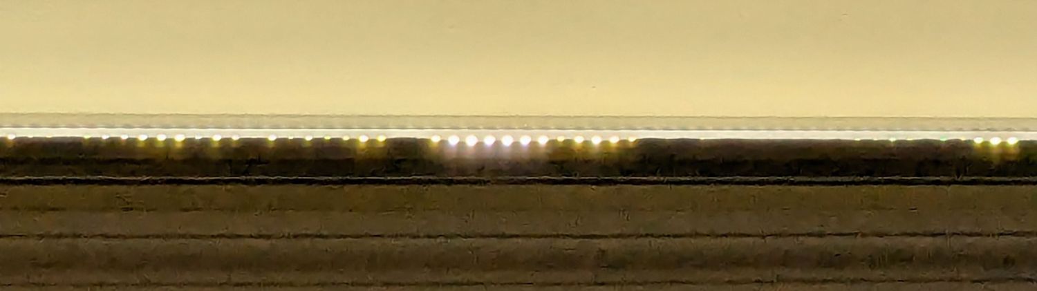
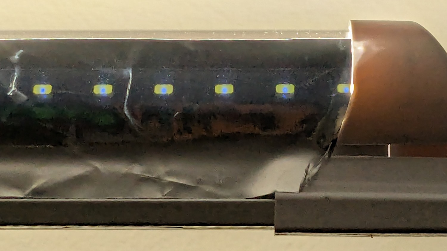
Contrary to what I expected, the Mylar reflectors must be at least an inch tall to avoid Baily’s Beads seen from across the room:
LED strip light – short reflector
With all that in mind, we’ll run these for a while to shake out any other improvements.
This file contains hidden or bidirectional Unicode text that may be interpreted or compiled differently than what appears below. To review, open the file in an editor that reveals hidden Unicode characters.
Learn more about bidirectional Unicode characters
This is a quick-and-ugly test to see how well aluminized Mylar will work as a reflective shade for some LED light bars eventually washing the Living / Sewing room ceiling with enough light to brighten the Sewing Table:
LED strip light – Mylar reflector – ugly fit
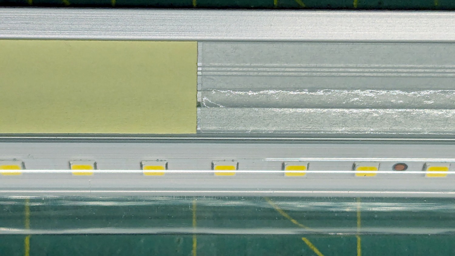
The key question: how well adhesive adheres Mylar to the pleasantly warm aluminum extrusion serving as the heatsink for 40 W of LEDs:
LED strip light – Mylar reflector – adhesive strips
Perhaps surprisingly, those ½ inch strips come from an A4 sheet by way of a paper cutter.
The LED bars will be directly visible, so bouncing the direct light against the wall reduces glare and puts it to good use.
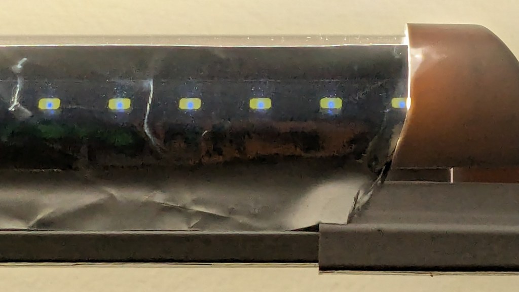
The Mylar strips are 1 inch wide, cut with a utility knife against a straightedge, although ⅞ inch seems adequate. The last LED over on the right sits at the endcap, so I will (try to) tuck the Mylar ends under the caps for a cleaner fit.
The bars have two 4 foot strips of LEDs in series, with a lump of circuitry buried in the aluminum extrusion that seems be a bridge rectifier and a small electrolytic capacitor. There’s not nearly enough capacitance to knock down the 120 Hz flicker and I have an uneasy expectation of stroboscopic effects on the sewing machines.
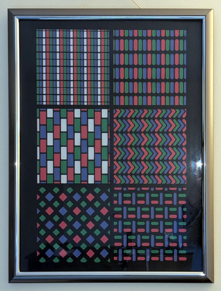
Having herded all the denizens of the Subpixel Zoo into one LightBurn workspace, framing them seemed appropriate:
SubPixel Zoo – wall hanging
We had some 18×24 inch frames which fit a standard construction paper size. The paper colors aren’t nearly as vivid as a real artist would want, but they’ll suffice for my simple needs.
Lay out a template and decide 180 mm blocks fill the frame:
SubPixels – LightBurn 18×24 template
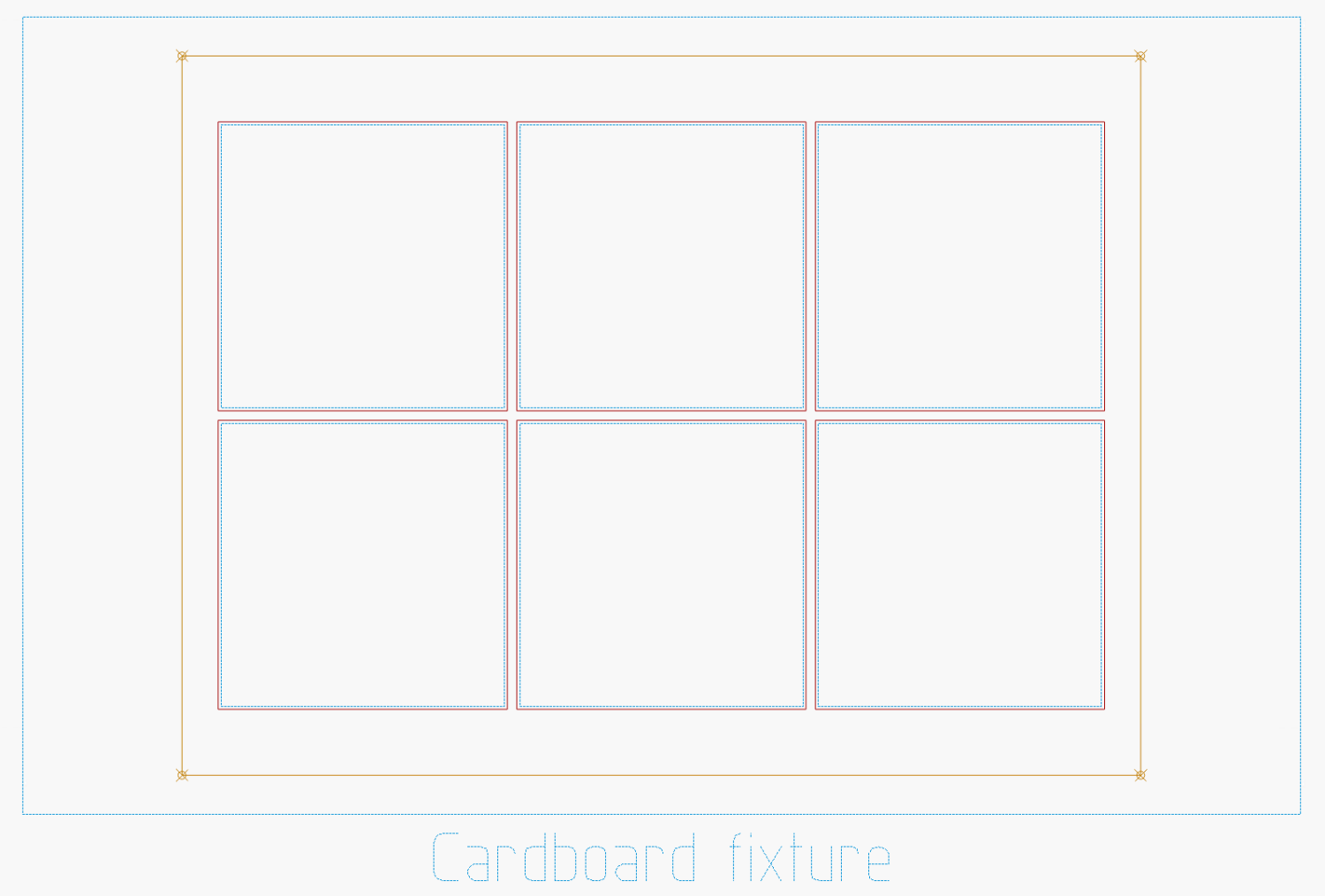
Offse the blocks 2 mm outward for cutting clearance and make a fixture:
SubPixels – LightBurn 18×24 fixture
The outer rectangle matches a blank sheet of corrugated cardboard cut by hand to fit the platform. The inner rectangle marks a line around the 18×24 inch position of the paper, giving me a mark within which I can center the paper well enough by eyeballometric approximation.
Cutting the blocks and marking the lines produces the template:
SubPixel Zoo – laser fixture and chaff
It’s held in place by four finger-crushingly strong magnets. If I ever do this again, I’ll throttle back on the power for the corner targets, because the laser cannot reach the top speed marking the outline, so it cut through the top layer of cardboard at the targets.
Embiggen the blocks to 180×180 mm, rotate them to their new orientation, then snap them into copies of the new template:
SubPixels – LightBurn 18×24 layers
I can only envision these things in the landscape orientation that will fit the laser platform, but you could build them in their final portrait orientation and rotate the result.
I put the template pattern in the middle of the LightBurn workspace and use Print and Cut to align the fixture with the corner targets. Then it’s just a sequence of laying a sheet of paper on the fixture, selecting the corresponding layout, hitting P to snap the layout to the center of the workspace, and Firing The Laser.
It’s not nearly as pretty as Mary’s quilts, but now I have a wall decoration of my very own.
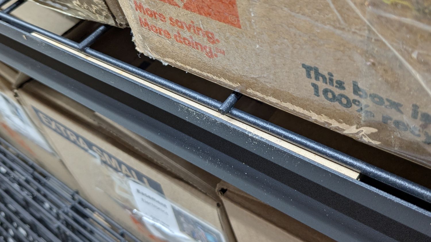
I’m finallyassembling the shelves for the last of the boxes cluttering the basement floor. Because the top of the wire shelf grid sits 4 mm below the top of the shelf rails, surely for some good reason, that pale strip is a 6 mm shim raising the grid just enough to let the boxes slide easily off without having to lift them over the rail.
It’s a pair of 3 mm thick MDF strips stuck together with tapeless sticky (a thin adhesive layer on backing paper), with the same adhesive holding the shim to the rail while I lay them down and plunk the shelf grid on top:
Wire Shelf Shim – side view
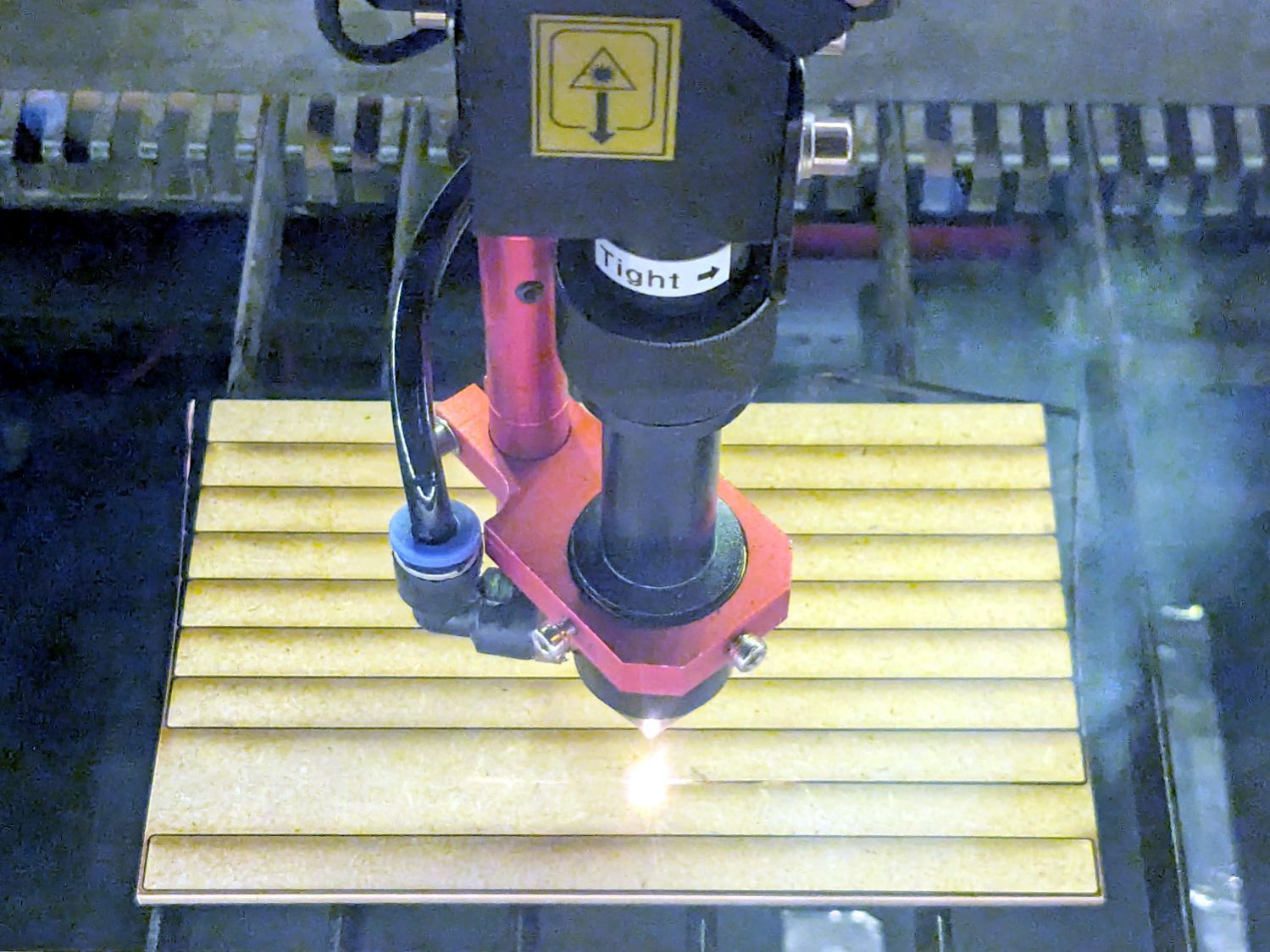
I made two sets of shims to fit the support rod spacing, with lengths carefully chosen to match two stacks from my Big Box o’ MDF Cutoffs, all 10 mm wide to fit the shelf rails:
Wire Shelf Shim – laser cutting
Admittedly, not all of the neatly rounded corners came through, due to slight variations in MDF sizing / Print-and-Cut alignment / whatever, but it’s a nearly zero waste way to turn stock into strips.
Each shelf needs 14 shims = 28 strips and I’m here to tell you if I had to bandsaw 140 little strips for each of three sets of shelves, well, I:
Probably wouldn’t ever get around to making them
Definitely would grumble about lifting those boxes, forever
The L4-L5 pair are part of an extensive human anatomic model locating all the pieces at their proper coordinates, so these two hovered about 800 mm above the XY plane. I ran them through the Grid:Tool mesh editor to center them at the XY origin, then put the bottom-most point at Z=0.
Rotating them individually in PrusaSlicer and painting only the most essential support got them to this state:
L4 L5 vertebrae – PrusaSlicer
Each one take about three hours, so I ran them individually to reduce surface blemishes and maximize the likelihood of happy outcomes. Worked like a champ.
The retina-burn orange disk is not anatomically correct, because the InterWebz apparently does not have a model for spinal cartilage:
L4 L5 vertebrae – assembled – disk detail
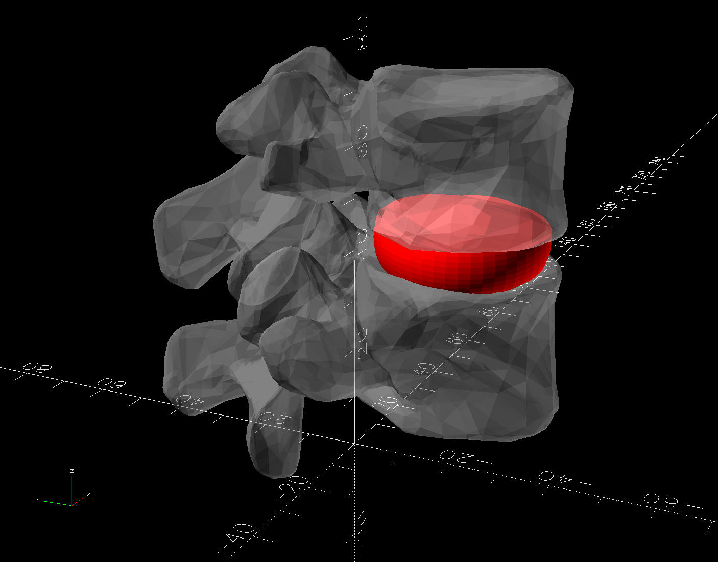
Instead, it’s a rounded cylinder resized into an oval, with its top and bottom surfaces formed by subtracting the vertebrae:
L4 L5 vertebrae disk – solid model
The OpenSCAD code doing the heavy lifting:
// Disk between L4 and L5 vertebrae
// Ed Nisley - KE4ZNU
// 2025-03-07

Layout = "Show";    // [Show,Build]

include <BOSL2/std.scad>

module Disk() {
  color("Red")
    difference() {
      translate([9,-18,36])
        rotate(110)
        resize([33,45])
        cyl(d=50,h=14,$fn=48,rounding=7,anchor=BOTTOM);
      import("../Spine/human-spinal-column-including-cervical-thoracic-and-lumbar-vertebra-model_files/L4 L5 vertebrae stacked.stl",
        convexity=10);
    }
}

if (Layout == "Show") {
  Disk();

  color("White",0.3)
      import("../Spine/human-spinal-column-including-cervical-thoracic-and-lumbar-vertebra-model_files/L4 L5 vertebrae stacked.stl",
        convexity=10);

}

if (Layout == "Build") {
  Disk();

}
All of the magic numbers come from eyeballometric measurement & successive approximation.
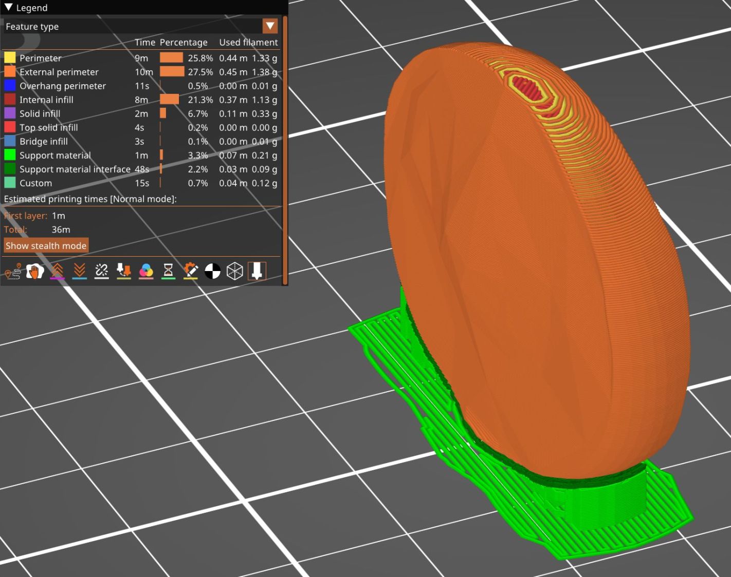
The Build layout left the disk floating in space, whereupon I used PrusaSlicer to reorient it edge-downward on the platform with painted-on support for minimal distortion:
L4 L5 vertebrae disk – PrusaSlicer
Two dots of E6000+ adhesive hold everything together.
All in all, it was a useful distraction. I’ve been vertically polarized for the last five days and it’s good to be … back.