The Axis user interface for EMC2 has a manual command entry mode, wherein you can type G-Code statements and EMC2 will do exactly what you say. That’s handy for positioning to exact coordinates, but I rarely use it for actual machining, as it’s just too easy to mis-type a command and plow a trench through the clamps.
OK, on a Sherline mini-mill, you’d maybe just snap off a carbide end mill, but you get the general idea.
I was making a simple front panel from some ancient nubbly coated aluminum sheet. The LCD and power switch rectangles went swimmingly.
Then I tried to mill an oval for the test prod wires using G42.1 cutter diameter compensation. I did a trial run 1 mm above the surface, figured out how to make it do what I wanted, then punched the cutter through the sheet at the center of the oval and entered (what I thought were) the same commands by picking them from the history list.
EMC2 now handles concave corners by automagically inserting fillets, so it must run one command behind your typing. I drove the cutter to the upper-right end of the oval (no motion) so it could engage cutter comp mode, entered the G2 right endcap arc to the lower edge (cuts straight to upper right), and then did something wrong with the next command.

The cutter carved the endcap properly, then neatly pirouetted around the end and started chewing out an arc in the other direction. Even looking at the command trace I can’t figure out what I mistyped, but as it turns out it doesn’t matter… I was using the wrong dimensions for the hole anyway.
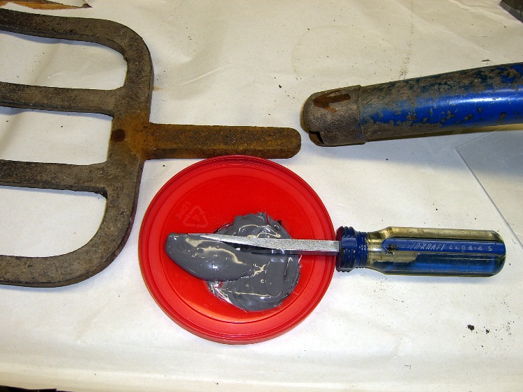
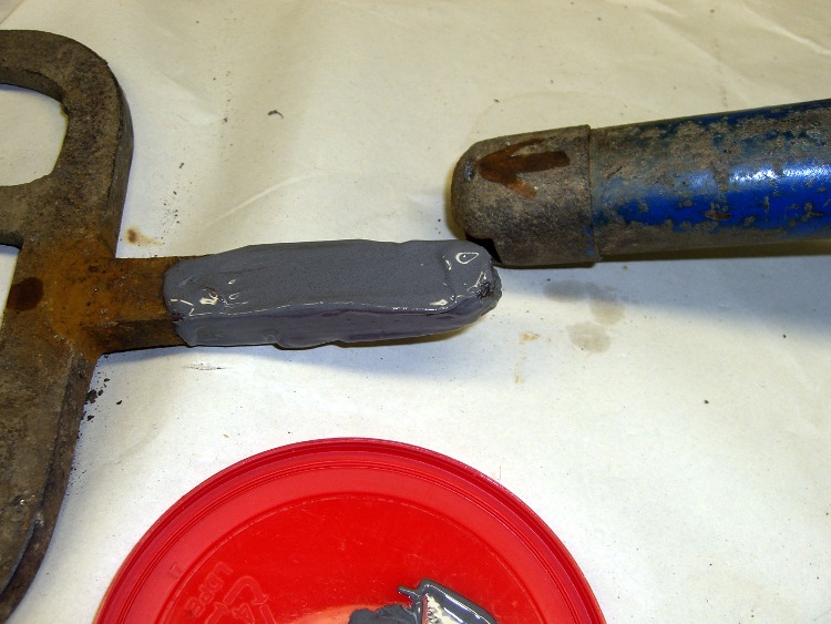
So it’s now patched with epoxy backed up by a small square of aluminum. When it’s done curing, I’ll manually drill a pair of holes at the right coordinates, manually file out the oval, shoot a couple of coats of paint, and it’ll be OK.
Nobody will ever know!
If I recall correctly, Joe Martin of Sherline was the first person to observe that, unlike word processing programs, CNC machines lack an Undo key…
Update: Like this…

The shoot-a-couple-of-coats thing did not go well: a maple seed landed on the front panel. Ah, well, it’s close enough. Here’s a trial fit; the bellyband height extenders on the sides need a dab of epoxy and a shot of paint, too, but I may never get a round ‘tuit for that.

It’s the long-awaited Equivalent Series Resistance meter…