Ed Nisley's Blog: Shop notes, electronics, firmware, machinery, 3D printing, laser cuttery, and curiosities. Contents: 100% human thinking, 0% AI slop.
The gear cover is an elaborate ten-pound iron casting, emblazoned with brass tags, and held in place by three 1/4-20 machine screws. The back gear covers, visible in the upper-left corner, are the same sort of wonderfully complex iron casting.
Make magazine, issue 17, has a snippet about an old sorghum press with instructions cast right into the machine, so you could literally RTFM: Read The Ferrous Metal. As it turns out, this 1928 South Bend lathe has instructions stamped into machined metal areas atop the change gear train: OIL.
Here’s a closeup…
Read The Ferrous Metal
Think about it: an iron casting, with machined-flat surfaces, stamped with instructions. How many man-hours did it take to get from raw material to finished product?
After un-jamming the 3-jaw chuck, I decided it was long past time to remove the accumulated slop in the lathe spindle. Modern lathes have a thrust bearing, usually with tapered needles or some such fancy arrangement. This lathe was shipped in 1928, has hulking brass bearings, and a nut to remove the slop.
If you’re following along in your copy of How to Run a Lathe, it’s Part Number 25 in the elevation view of the lathe, at least in my 1966 “Revised Edition 66”. Various copies are available here & there, but link rot seems to be a common failing.
The gear on the end of the spindle has 30 teeth and the nut thread is 20 TPI. After all these years, turning the nut 3 teeth takes the spindle from “free spinning” to “jammed tight”. The nut had accumulated about four teeth worth of end play before the “free-spinning” stage.
Call it 0.010 inches of play. Enough that I should have adjusted it out long ago, but not a big deal when there’s a tailstock pushing the work against the headstock bearing.
I don’t do any lengthy machining operations that would tend to heat the bearings and reduce the end play. If you do, that’s certainly something to consider.
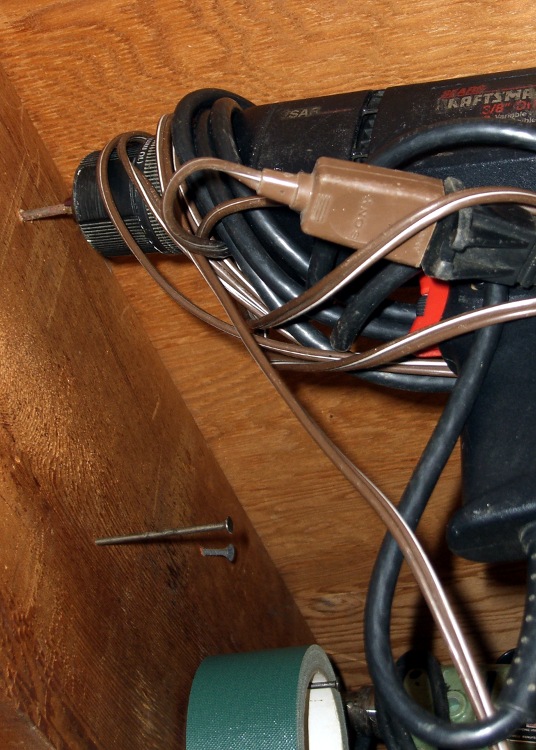
When you hang an electric hand drill on a nail pounded into a floor joist, you want the chuck jaws to just clear the nail. Too large and the drill tends to fall off. Too small and it won’t go.
I took way too long to figure this out, but…
Adjust the chuck properly just once, then run a fat marker around the jaws.
It’s trivially easy to get it right forever after: spin the chuck adjustment until the marks line up with the chuck nose and hang the drill up.
Some years ago, a friend convinced me I needed an Inova X1 LED flashlight. He was right; I’ve carried one in my belt pack ever since and, in fact, added a couple of X5s to the household armory.
Perforce, this is an old X1 with a coated glass lens to make the best of the LED. Newer X1s don’t have (or, likely) need the lens, as LED technology has made great strides in the last few years.
I couldn’t bear the thought of that lens rattling around in my belt pack, chewed upon by the assortment of other crap in there. So I made a lens protector: a length of heatshrink tubing with a polypropylene window. You might want to do the same for your flashlight to keep from grinding up the optical surfaces on its shiny end.
This tubing has an internal thermoplastic glue, but ordinary tubing would likely work as well. Position the tubing over the end of the flashlight with a few millimeters sticking out. Cut a circle from the clamshell case around some piece of consumer electronics, drop it on top of the lens, and shrink the tubing around the flashlight: watch it wrap right over the end and hold the circle in place. A dot or three of urethane glue may help for glue-less tubing.
It’s transparent enough for most purposes, but when you really need more light or a tighter beam, pull it off. That’s aided by dabbing a trace of oil on the X1, which you can get directly from the (outside) of your nose. Yeah, gross, but it’s a renewable natural resource…
Some years ago a friend brought a favorite old camera that he’d just rediscovered. As you might expect, the exposure meter battery had long since died and its lid was rust-welded in place. Alas, he’d tried and failed to remove the lid by applying, mmmm, inappropriate tools to the coin slot.
I proposed building a quick-and-dirty pin wrench from an aluminum knob, which requires a matching pair of holes in the lid. Given that the lid was already pretty well pooched, he had no objection.
IIRC, I laid a strip of masking tape over the lid, laid out the holes perpendicular to the slot, then drilled them out by eyeball. The trick is to avoid drilling into the battery; it’s likely all dried out by now, but there’s no reason to release any more of that glop than absolutely necessary.
Battery cover wrench
Then I turned the threaded boss off the bottom of the knob and drilled two slightly larger holes separated by the same distance. This would be ideal for manual CNC, but I didn’t have the Sherline at the time, difficult though that may be to imagine.
When you can’t do precision work, epoxy is your friend.
Lay new tape over the battery lid
Cut two lengths of music wire with a diameter to match the holes in the battery lid using a Dremel abrasive cutoff wheel
Stuff the wire stubs into the holes, wipe off excess epoxy
Jam the pins through the tape into the holes in the battery lid
Wait for a few minutes…
You can see the top pin is slightly offset in its hole, but the epoxy ensures that the pins are an exact fit to the lid. The tape prevents the wrench from becoming one with the battery lid. Not drilling into the battery means the pins bottom out on the battery. Music wire means the pins won’t bend; copper wire doesn’t work in this application.
If you’re good with the Dremel, the pins will be not only the same length, but the proper length. IIRC, I made them a bit long and then trimmed them to fit.
Battery lid removed
When the epoxy cures:
Remove the wrench
Remove the tape
Install the wrench
Twist the lid right off.
Works like a champ!
Much to our surprise, the inside of the battery compartment wasn’t a mass of corrosion and the threads were actually in pretty good shape, all things considered. It’s not clear why the lid was so corroded, but there you have it.
He went home happy… taking the wrench along, although we hope it’ll never be used again.
(I found these pix while I was looking for something else. My close-up technique has improved over the years: a tripod, bright lights, and the smallest possible aperture are my friends.)
Having had both of our commercial antenna mounts fail, I decided to make something that could survive a direct hit. It turns out that the new mounts are utterly rigid, which means the next failure point will be either the antenna mast or its base structure. We’ve occasionally dropped the bikes and when the antenna hits something on the way down, the mount is not the thing that bends…
Incidentally, the Nashbar 5-LED blinky white light aimed rearward seems to push motorists over another few feet to the left. Nobody quite knows what we are from a distance, but they do notice that something is up ahead. That’s just about as good as it gets; we tend to not ride in the wee hours of the morning when bike lights just give drunks an aiming point.
Rough-cut stock
The overall structure is a 2-inch square aluminum extrusion, with a hole in the top that matches the right-angle SO-239 base connector salvaged from the Diamond mount and a 1/2″ nylon stiffener plate in the middle. A pair of relentlessly square circumferential clamps attach it firmly to the top seatback rail. A coaxial cable pigtail ensures that the antenna base makes good electrical contact with the seat. I’m not convinced the bike makes a good counterpoise, so we’re now using dual-band antennas that are half-wave on VHF.
Stainless-steel hardware holds everything together, as I’m sick and tired of rust.
Drilling box beam
Not having a huge drill, I helix-milled the SO-239 hole, then reached down through the box to drill the hole for the plastic block retainer screw. Flip the box in the vise, drill four holes for the clamps (I love manual CNC for that sort of thing), manually deburr the holes, and it’s done.
The block of plastic is a tight slip fit inside the box extrusion, with slightly rounded corners to suit. I milled the slot across the top to a slip fit around the SO-239 connector.
The two clamps were the most intricate part of the project and got the most benefit from CNC.
Helix-milling the seat-bar clamp
The clamp hole must have exactly the same diameter as the seat top tube. I helix-milled the hole to an ordinary 5/8″; I have trouble drilling holes that large precisely in the right spot with the proper final diameter. Milling takes longer, but the results are much better.
Helix-mill the other block while you have the position set up, then flip and reclamp to drill the pair of holes that match the box extrusion. Drill 10-32 clearance (#9) all the way through.
Flycutting the Clamp Slit
Bandsaw the blocks in half, paying some attention to getting the cut exactly along the midline, then flycut the cut edge to make it nice & shiny & even. That should result in 1 or 2 mm of slit between the blocks when they’re clamped around the seat rail.
Finished seat-bar clamps
Break those relentlessly sharp edges & corners with a file.
I finagled the dimensions so a 1-1/2″ socket-head cap screw would have just enough reach to fill a nut, with washers under the screw and nut. Your mileage may vary; I’ve gotten reasonably good at cutting screws to length.
Normally, you tap one side of each clamp for the screws, but in this situation I didn’t see much point in doing that: the box must attach firmly to the clamps and I was going to need some nuts in there anyway.
Finished parts
With all those parts in hand, assembly is straightforward. Secure the SO-239 with its own thin nut, screw the plastic block in place, hold the clamps around the seat bar, poke the cap screws through, dab some Loctite on the threads, install nuts, and tighten everything. That all goes much easier with four hands!
The grounding braid fits into a huge solderless connector that must have been made with this application in mind. It originally fit a 1/2″ lug, but with enough meat that I could gingerly file it out to 5/8″ to fit the SO-239 inside the aluminum extrusion. I’ve had those connectors for years without knowing what they were for!
I eventually came up with a simpler and even more ruthlessly rugged mount that’ll appear in my column in the Autumn 2009 Digital Machinist. More on that later… [Update:There]
We used Diamond K540KM truck mirror-bracket antenna mounts clamped to the top seatback rail on our Tour Easy recumbents for several years, but they weren’t entirely satisfactory. The vibration from our ordinary on-road bike rides (a TE isn’t an off-road bike!) fractured the stamped-steel base after four years.
Antenna Bracket Repair
I fixed that by screwing a steel plate across the crack. It became obvious that these mounts weren’t suited to the application when the second mount failed shortly thereafter.
Broken Diamond K540KM Antenna Mount
But we kept using them and, as you might expect, Mary’s mount failed in the middle of a 350-mile bike ride when the die-cast support dingus broke. The fresh granular metal fracture looks dead white in the picture.
I lashed the pieces together with a multitude of cable ties and we completed the mission. When I rolled our bikes into the Basement Laboratory Bike Repair Wing after returning home, the mount on my bike failed.
These mounts aren’t intended for “high vibration” applications and, it seems, bicycles produce much higher vibration than trucks. I’m certain that the frequency range is higher, although I’m not sure about the amplitude.
Obviously, it was time for something better… which meant some quality shop time. More on that tomorrow.