In the process of fixing something else, I discovered my favorite desktop razor knife had a loose blade. There being nothing like a new problem to take one’s mind off all one’s previous problems, I obviously had to fix it before proceeding:
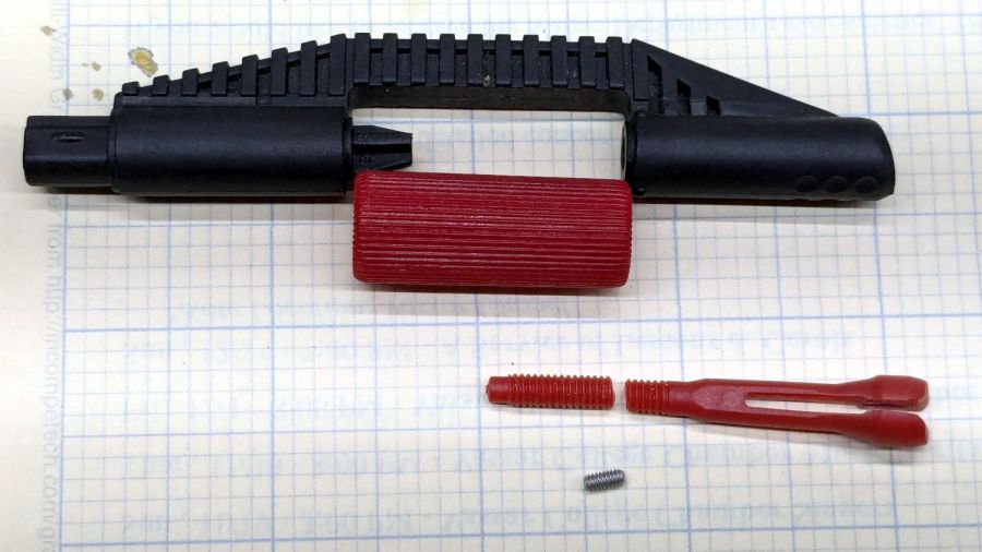
Come to find out the plastic screw tightening the blade collet had snapped. The remaining stub stuck out from the red ribbed nut just far enough to prevent sliding the nut out of the black plastic body, but jamming a small screwdriver through the body got enough traction to unscrew the stub. It’s threaded 8-32, despite being old enough to be Made in Taiwan.
The red plastic feels like HDPE or a similar un-glue-able material, so it was going to need a mechanical splice. A tiny 2-56 setscrew falls in the class of things my buddy Eks describes as “If your design needs those, you’re doing it wrong”, but sometimes you gotta do what you gotta do.
For the record, a 2-56 setscrew requires a 35 mil hex wrench. My tiny ziplock bag with tiny hex wrenches has one:
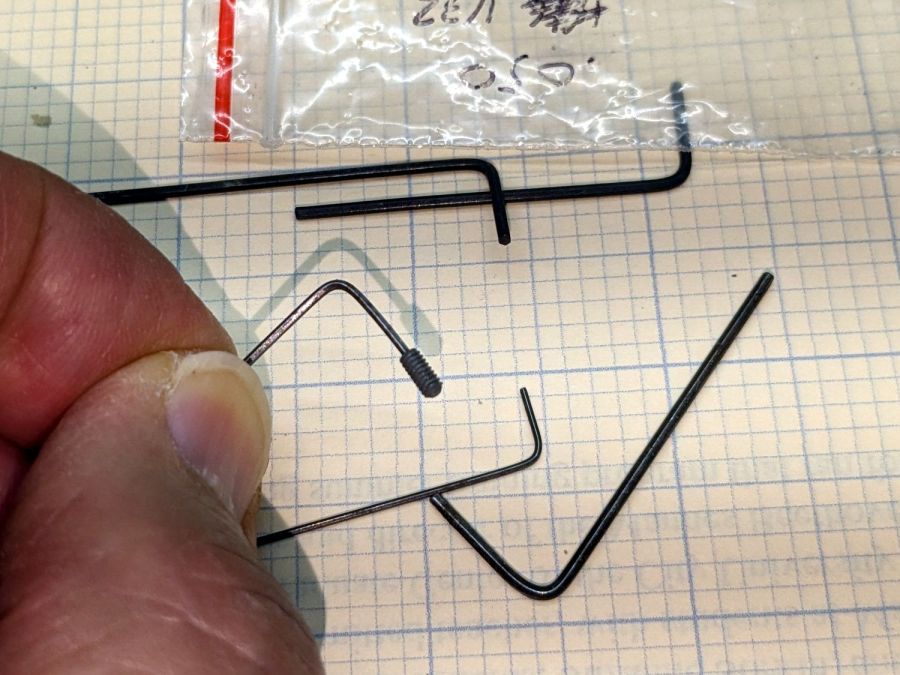
The little wrench in the background measures 28 mils for 0-80 setscrews, of which I have none and don’t expect to get any.
Anyhow, facing, drilling, and tapping the stub proceeded handily:
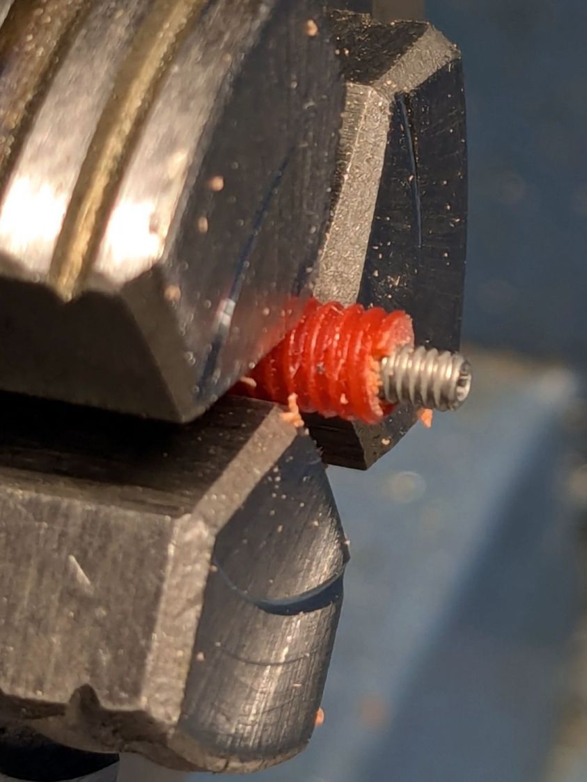
You’d think I hadn’t faced off the end, but you’d be wrong. As far as I can tell, the end of the screw would be happy to break for as long as I’d be willing to try cutting it. Perhaps this indicates why it broke and suggests this repair will be temporary, at best.
Doing the same to the collet required a clamp to fit its slightly oblong body:
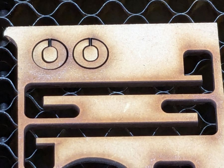
Those of long memory may recall the hooks.
Which then worked exactly as you’d expect:
That’s aggressive stick-out for a little plastic rod, but sissy cuts saved the day; it faced / drilled / tapped easily enough:
Despite the non-glue-able plastic, I tucked some JB PlasticBonder into the recesses, screwed everything together, and coerced the 8-32 threads into alignment inside the plastic nut:
Reassemble in reverse order after the adhesive set up:
Done!
Now, what was I doing?