Ed Nisley's Blog: Shop notes, electronics, firmware, machinery, 3D printing, laser cuttery, and curiosities. Contents: 100% human thinking, 0% AI slop.
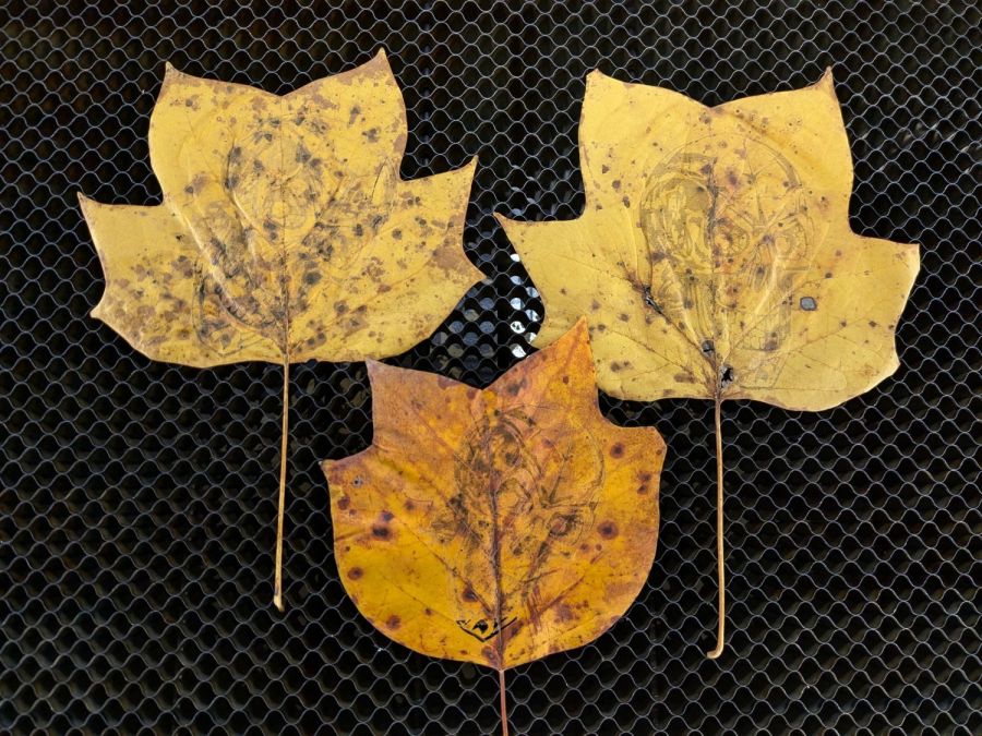
Three months of outdoor exposure suggest that laser test paper can survive use as a plant tag for one growing season, at least when it remains flat:
Laser test paper – small plant labels – 3 month exposure
The two upper tags demonstrated the paper has no flexibility worth mentioning, so it cannot become a tag wrapped around a stem.
The two lower labels spent their time tucked into a window frame where they got plenty of sun & rain without the benefit of a backing plate. Looks good to me!
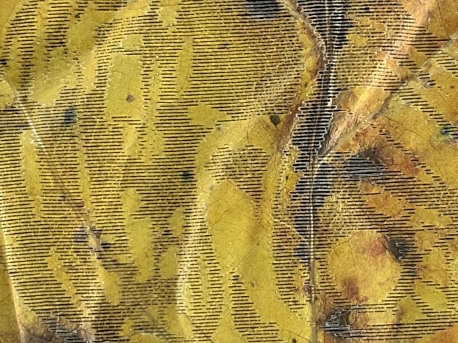
Contrary to my expectation, the craft adhesive sheet behind this label survived intact, although the label itself took some damage, perhaps from the more direct sunlight out on the deck:
Laser test paper – plant marker – 3 month exposure
In any event, they look Good Enough™ for our simple needs and next year’s plants will be properly labeled.
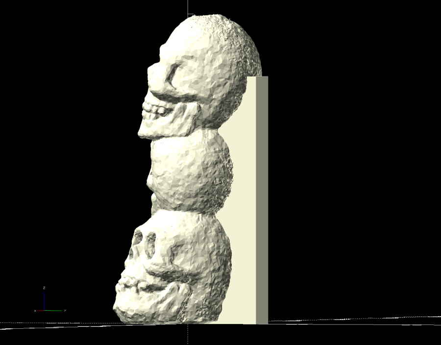
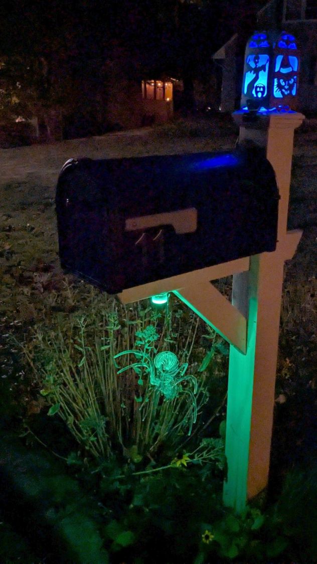
With only days to spare, I decorated the doorbell button:
Doorbell button skulls – installed
Yeah, I jammed Sharpies in the eye sockets, but they look exactly the way they should. The middle skull is in the middle of the actuator in the hope that’s where it’ll get pushed.
The “carbon fiber” part of PETG-CF consists of very very short fibers, unlike the longer fibers in real carbon fiber materials, so the strength is nowhere near what you might expect from the marketing. I knew this going in and the break wasn’t surprising.
The humidifier that Came With The House™ had a lid with two broken plastic hinges that I figured I could never replace, but while cleaning out the fuzz for the upcoming season I found one missing piece stuck inside the lid. Given a hint, I glued it back in place:
Humidifier Hinge – outlined
There’s a strip of duct tape around the outside holding the fragment in place while the adhesive cured.
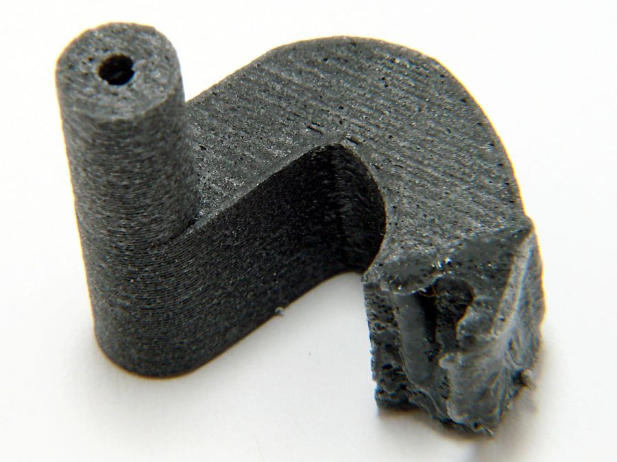
A manual curve fit to the image in Inkscape produced the red outline, which gets saved as a plain SVG and fed into OpenSCAD to create a solid model:
Humidifier Hinge – solid model
The cylinder doesn’t exactly fit the end of the hinge, but it’s close enough. The straightforward OpenSCAD code making that happen:
The pin has a hole for a M2 screw, but contemplation of the broken pieces suggested the pin wasn’t the weakest link, which later experience confirmed.
Figuring I’d need only one hinge, I made a spare for fitting:
Humidifier hinge – on platform
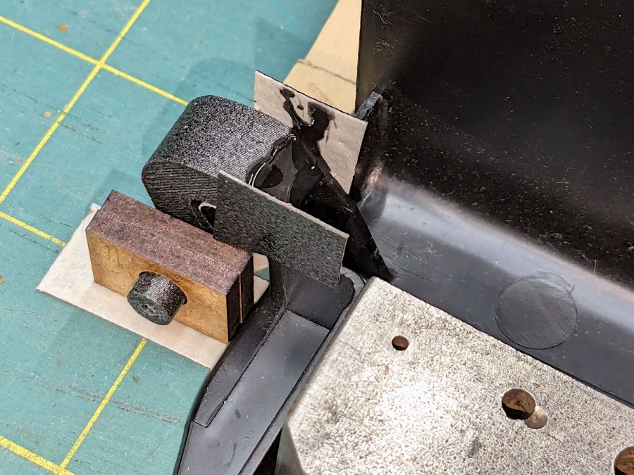
The unmodified part fit just about perfectly, whereupon a completely ad-hoc fixture involving a pair of laser-cut MDF slabs, a craft stick epoxy mixer, and more duct tape held it in place while the adhesive cured:
Humidifier hinge – fixturing
The hinge pin turned out to be half a millimeter too long, which is easily fixed, and it worked fine:
Humidifier hinge – installed
That’s more duct tape wrapped around the perimeter to hold the pieces in place, should it break again.
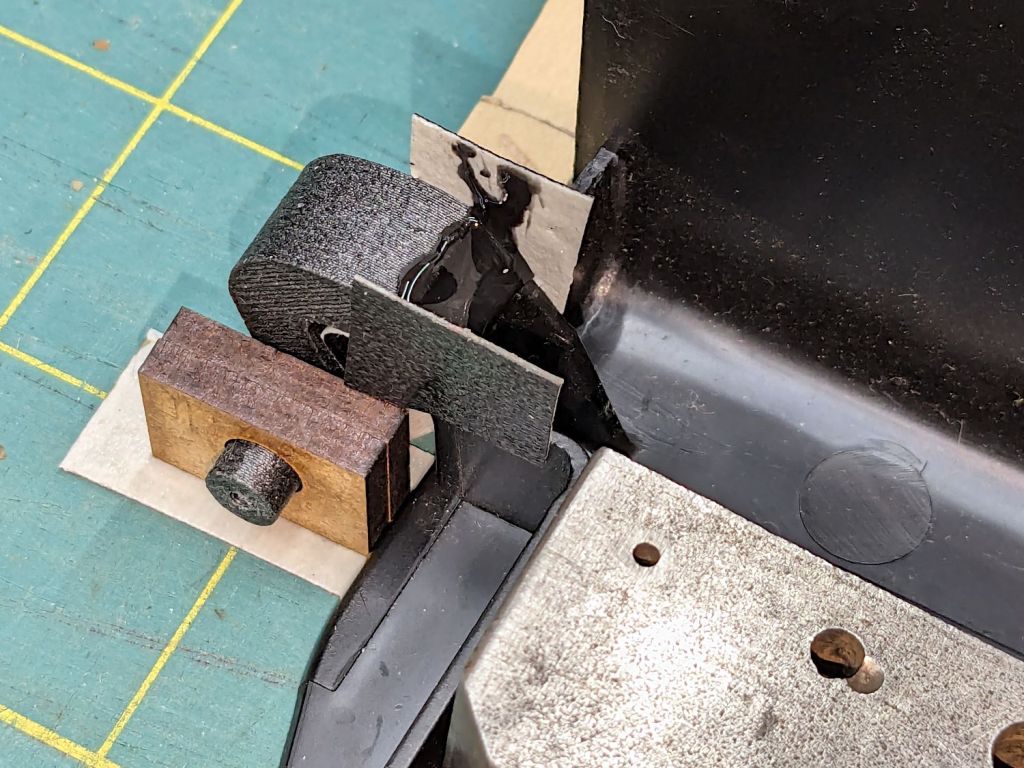
Which, I regret to report, occurred on the way up the stairs from the Basement Shop™ when the lid slipped from my grasp, fell away from the rest of the humidifer’s top panel, and jammed open:
Humidifier hinge – break
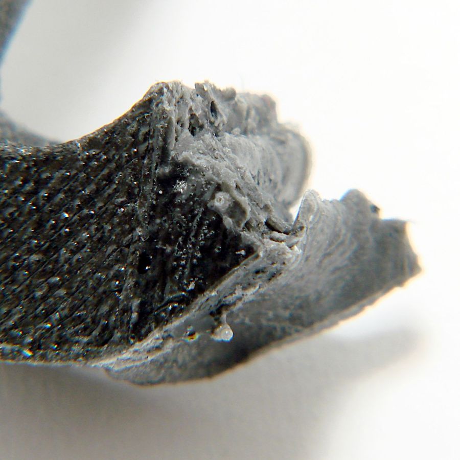
The PETG-CF part held together, the adhesive remained bonded to both pieces, but the original plastic fractured just below the joint. A closer look from the other side shows the break:
Humidifier hinge – break detail
The other hinge broke about where it did before.
So the humidifier remains in service with the lid in status quo ante and a small bag inside holding the fragments for the next return to the shop.
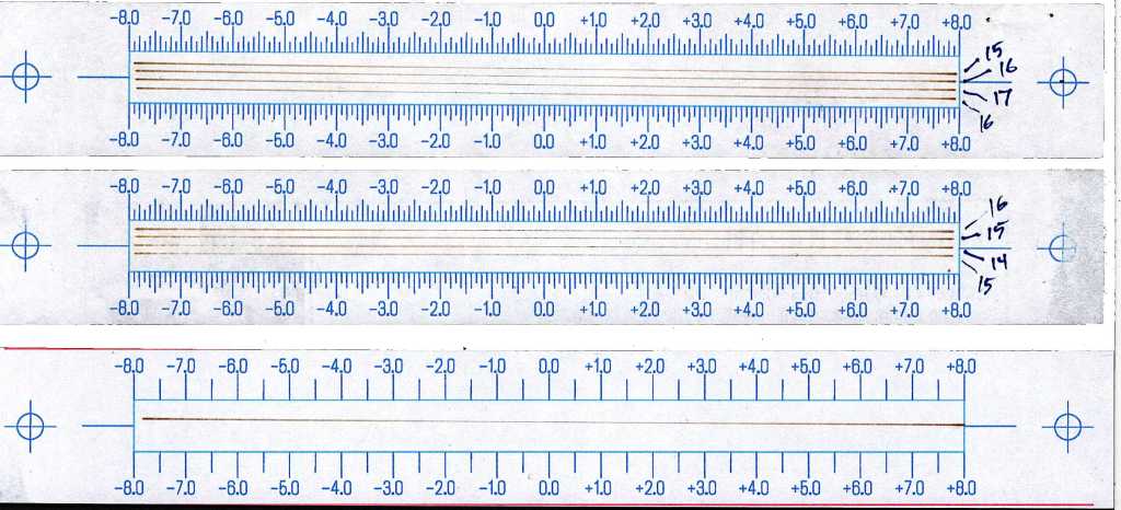
A few ramp tests with various Focus Distance + Home Offset settings as noted:
Ramp Test Targets – 14-17 mm
The bottom test was at 15 mm, which (contrary to previous estimates) seems to center the narrow band round 0.0 mm. Given the depth of field, a millimeter one way or the other likely doesn’t matter, particularly given the mmm lack of flatness in many materials.
The controller settings making it happen:
KT332N Autofocus settings
What they mean:
Home Offset = distance to retract after the autofocus “pen” = switch activates so the tip of the pen clears the material
Focus Distance = distance beyond Home Offset to put the focal point at the surface of the material (or wherever you want)
Enable Homing = makes autofocus work at the push of a button
Homing Speed = how fast the platform moves while focusing
Getting the focus right really makes the laser cut like it should!